Under management it is customary to understand the machine tool as a set of influences on its mechanisms that ensure that these mechanisms perform the technological cycle of processing, and under control system- a device or a set of devices that implement these effects.
Manual management is based on the fact that the decision to use certain elements of the work cycle is made by a person - the operator of the machine. The operator, based on the decisions made, turns on the corresponding mechanisms of the machine and sets the parameters of their work.
Manual control operations are carried out both in non-automatic universal and specialized machines for various purposes, and in automatic machines. V automatic machines manual control is used to implement adjustment modes and special elements of the work cycle.
In automatic machines, manual control is often combined with digital indication of information coming from position sensors of the executive bodies.
Automatic control lies in the fact that decisions on the use of elements of the work cycle are made by the control system without the participation of the operator. She also issues commands to turn on and off the mechanisms of the machine and controls its operation.
processing cycle called the set of movement of the working bodies, repeated during the processing of each workpiece. The complex of movements of the working bodies in the cycle of the machine is carried out in a certain sequence, i.e. according to the program.
Control program - this is a set of commands corresponding to a given algorithm for the functioning of the machine for processing a particular workpiece.
Algorithm name a way to achieve the goal (solution of the problem) with an unambiguous description of the procedure for its implementation.
By functional purpose, automatic control can be divided as follows:
control of constant repetitive processing cycles (for example, control of modular machines that perform milling, drilling, boring and thread-cutting operations by performing cycles of movement of multi-spindle power heads);
control of variable automatic cycles, which are set in the form of individual material models-analogues for each cycle (copiers, sets of cams, stop systems, etc.) and etc.;
CNC, in which the program is specified in the form of an array of information recorded on one or another medium. Control information for CNC machines is discrete, and its processing in the control process is carried out by digital methods.
Cyclic program control (CPU)
Cycling system program control(CPU) will allow you to partially or completely program the cycle of the machine, the processing mode and tool change, as well as set (using the preliminary adjustment of the stops) the amount of movement of the executive bodies of the machine. It is an analog closed-loop control system (Figure 1) and has a sufficiently high flexibility, i.e., it provides an easy change in the switching sequence of the equipment (electrical, hydraulic, pneumatic, etc.) that controls the elements of the cycle.
Picture 1– Cyclic program control device
The cycle programmer contains block 1 for setting the program and block 2 for its phased input (a program stage is a part of the program that is simultaneously entered into the control system). From block 1, information enters the automation circuit, consisting of block 3 for controlling the cycle of the machine and block 4 for converting control signals. The automation circuit (which, as a rule, is performed on electromagnetic relays) coordinates the work of the cycle programmer with the executive bodies of the machine and the sensor feedback; strengthens and multiplies teams; can perform a number of logical functions (for example, ensure the execution of canned cycles). From block 3, the signal enters the actuator, which ensures the processing of the commands specified by the program and includes actuators 5 (drives of the executive bodies of the machine, electromagnets, clutches, etc.). The latter work out the stage of the program. Sensor 7 controls the end of processing and through block 4 instructs block 2 to turn on the next stage of the program. Sensor 7 controls the end of processing and through block 4 instructs block 2 to turn on the next stage of the program. To control the end of a program step, travel switches or time relays are often used.
In cyclic control devices in numerical form, the program contains information only about the cycle of processing modes, and the amount of movement of the working bodies is set by setting the stops.
The advantages of the CPU system are simple design and maintenance, as well as low cost; the disadvantage is the complexity of the dimensional adjustment of stops and cams.
It is advisable to use CNC machines in the conditions of serial, large-scale and mass production of parts of simple geometric shapes. CNC systems are equipped with turret-turning, turning-milling, vertical drilling machines, modular machines, industrial robots (IR), etc.
The CPU system (Figure 2) includes a cycle programmer, an automation circuit, an actuator and a feedback device. The CPU itself consists of a cycle programmer and an automation circuit.
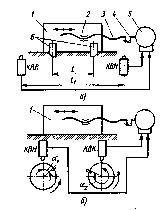
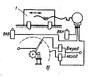
Figure 2 -
Based on the achievements of cybernetics, electronics, computer technology and instrumentation, fundamentally new software control systems have been developed - CNC systems that are widely used in machine tool building. In these systems, the value of each stroke of the executive body of the machine is set using a number. Each unit of information corresponds to a discrete movement of the executive body by a certain amount, called the resolution of the CNC system or the price of the impulse. Within certain limits, the executive body can be moved by any amount, a multiple of the resolution. The number of pulses that must be applied to the drive input in order to carry out the required displacement L is determined by the formula N = L/q, where q is the price of the impulse. The number N, written in a certain coding system on an information carrier (punched tape, magnetic tape, etc.), is a program that determines the amount of dimensional information.
Under the CNC machine understand the control (according to a program specified in an alphanumeric code) by the movement of the executive bodies of the machine, the speed of their movement, the sequence of the processing cycle, cutting mode and various auxiliary functions.
CNC system is a set of specialized devices, methods and tools necessary for the implementation of CNC by a machine tool. CNC device (CNC) is a part of the CNC system designed to issue control actions by the executive body of the machine in accordance with the control program (CP).
The block diagram of the CNC system is shown in Figure 3.
Detail drawing (BH), to be processed on a CNC machine, simultaneously enters the system program preparation s (SPP) and technological preparation system (STP). STP provides SPP data on the developed technological process, cutting mode, etc. Based on these data, a control program is developed (UP). Adjusters install fixtures and cutting tools on the machine according to the documentation developed in STP. The installation of the workpiece and the removal of the finished part is carried out by the operator or automatic loader. Reader (SU) reads information from the program carrier. The information goes to CNC, it issues control commands to target mechanisms (CM) machine, carrying out the main and auxiliary movements of processing. Feedback sensors (dos) on the basis of information (actual positions and speed of movement of actuating units, the actual size of the treated surface, thermal and power parameters of the technological system, etc.) control the amount of movement CM. The machine contains several CM, each of which includes: an engine (DV), which is a source of energy; transfer P, serving to convert energy and transfer it from the engine to the executive body ( AND ABOUT); actually AND ABOUT(table, sled, caliper, spindle, etc.) that performs the coordinate movements of the cycle.
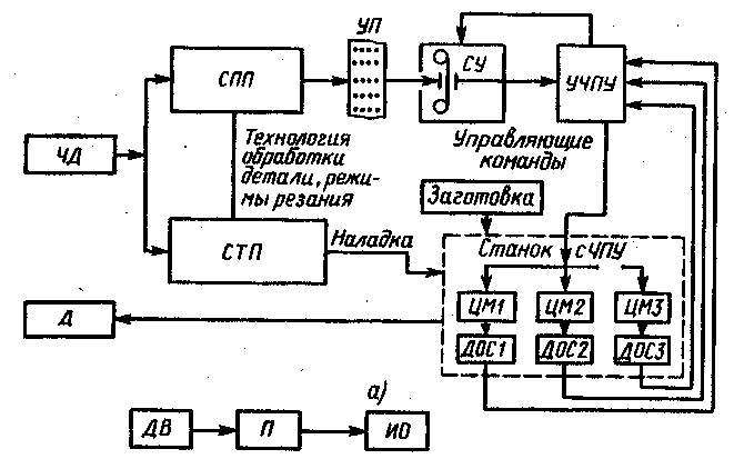
Figure 3– Structural diagram of the CNC system
Universal CNC systems provide the user and operator with great possibilities. They can be adapted by programming to a wide class of objects, including different machines; provide at the same time all types of interpolation - linear, circular, parabolic, etc., as well as preparation and debugging control program directly at the machine in interactive mode. The control program can be stored in memory and read from it during processing, which in some cases makes it possible to dispense with the preliminary input of the program by reading it from the program carrier. CNC systems have ample opportunities for editing the program, provide the ability to automatically correct (from memory) without using console correctors. It should be noted that there are special diagnostic programs for checking the operation of nodes in order to identify sources of malfunction, as well as the possibility of storing in memory information about the systematic errors of kinematic chains and eliminating or compensating these errors when playing a given profile; the possibility of introducing restrictions on the processing zone into the system in order to avoid marriage or breakdown of the machine; return to any point where the processing was interrupted. Universal CNC systems work in linear and polar coordinates, providing the transformation of coordinate axes, for example, when using programs compiled for vertical milling machines on horizontal milling machines.
The main operating mode of the CNC device is automatic mode. In the process of automatic processing of the control program, a wide range of tasks of different levels of complexity is solved: polling the buttons of the operator's console; distribution and issuance of data for indication on the operator's console; calculation of the current position by coordinates and the issuance of information to the operator's console; calculation of processing cycles; calculation of equidistant offset; introduction of correction; error compensation; interrogation of electroautomatic sensors; interrogation of readiness signals of input-output devices; interpolation; speed calculation; calculation of acceleration-deceleration modes; polling feedback sensors; issuance of control actions on technological equipment; analysis of the current time; time control of the control program; analysis of the execution of the program contained in this frame; preparation of initial information for processing the next frame.
The CNC system can be modified depending on the type of program carrier, the method of encoding information in the NC and the method of its transfer to the CNC system.
Numerical control (CNC)- this is a control in which the program is set in the form of an array of information recorded on some medium. Control information for CNC systems is discrete and its processing in the control process is carried out by digital methods. Management of technological cycles is almost universally carried out using programmable logic controllers, implemented on the basis of the principles of digital electronic computing devices.
Programmable controllers
Programmable controller (PC ) - This is a device for controlling the electroautomatics of a machine using certain algorithms implemented by a program stored in the device's memory. A programmable controller (commander) can either be used autonomously in the CPU system, or be part of common system control systems (e.g. flexible production module control systems (GPM)), as well as be used to control the equipment of automatic lines, etc. The block diagram is shown in Figure 4.
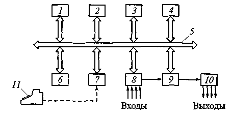
Figure 4- Structural diagram of a programmable controller:
1 - processor; 2 - timer and counters; 3 - reprogrammable memory; 4 - random access memory (RAM); 5 - common bus for block communication; 6 - communication unit with the CNC device or computer; 7 - block for connecting the remote control for programming; 8 – input modules; 9 - input-output switch; 10 - output modules; 11 – programming console with keyboard and display.
Most PLCs have a modular design that includes a power supply, processor unit, and programmable memory, as well as various I/O modules. Input modules (input modules) generate signals from various peripheral devices (limit switches, electrical devices, thermal relays, etc.). Input signals have, as a rule, two levels "O" and "1". Output modules (output modules) supply signals to the controlled actuators of the machine's electric automation (contactors, starters, electromagnets, signal lamps, electromagnetic clutches, etc.). With an output signal of "1", the corresponding device receives a command to turn on, and with an output signal of "O" - to turn off.
The processor with memory solves the logical tasks of controlling the output modules based on the information received by the input modules and the control algorithms entered into the memory. Timers are set to provide time delays in accordance with the cycles of work PC. Counters also solve the tasks of implementing a work cycle PC.
Entering the program into the processor memory and debugging it are performed using a special portable remote control, temporarily connected to PC. This remote control, which is a program recording device, can serve several PC. In the process of recording the program, the remote control display shows the current state of the controlled object in relay symbols or legends. Program input can also be carried out through a communication unit with a CNC device or a computer.
The entire program stored in memory can be divided into two parts: the main one, which is an object control algorithm, and the service one, which ensures the exchange of information between PC and managed object. The exchange of information between the PC and the controlled object consists in polling inputs (receiving information from the controlled object) and switching outputs (issuing a control action to the controlled object). In accordance with this, the service part of the program consists of two stages: polling inputs and switching outputs.
Programmable controllers use various types of memory , which stores the machine's electroautomatic program: electrical reprogrammable non-volatile memory; RAM with free access; erasable by ultraviolet radiation and electrically reprogrammable.
Programmable control has a diagnostic system: inputs / outputs, errors in the operation of the processor, memory, battery, communication and other elements. To simplify troubleshooting, modern intelligent modules have self-diagnostics.
Programmable Logic Controller (PLC) is a microprocessor system designed to implement logic control algorithms. The controller is designed to replace relay-contact circuits assembled on discrete components - relays, counters, timers, hard logic elements.
Modern PLC can process discrete and analog signals, control valves, stepper motors, servo drives, frequency converters, and regulate.
High performance makes it worth using PLC wherever logical processing of signals from sensors is required. Application PLC ensures high reliability of equipment operation; simple maintenance of control devices; accelerated installation and adjustment of equipment; fast updating of control algorithms (including on operating equipment).
In addition to the direct benefits of using PLC, due to low price and high reliability, there are also indirect ones: it becomes possible to implement additional functions without complicating or increasing the cost finished products, which will help to fully realize the capabilities of the equipment. A large assortment PLC makes it possible to find optimal solutions for both simple tasks and complex automation of production.
Software carriers
The program of work of the executive bodies of the machine is set using the program carrier.
Program carrier is the storage medium on which the control program is recorded.
The software may contain geometric, so technological information. Technological information provides a certain cycle of the machine, contains data on the sequence of putting into operation of various tools, on changing the cutting mode and turning on the cutting fluid, etc., and geometric - characterizes the shape, dimensions of the elements of the workpiece and tool being processed and their relative position in space.
Most common software carriers are:
card - made of cardboard, has the shape of a rectangle, one end of which is cut off for orientation when inserting the card into the reader. The program is recorded by punching holes in place of the corresponding numbers.
eight-track punch tapes (Figure 5) 25.4 mm wide. Transport track 1 serves to move the tape (using the drum) in the reader. Working holes 2, carrying information, are punched on a special device called a perforator. Information is applied to the punched tape in frames, each of which is an integral part of the UE. In a frame, only such a set of commands can be recorded, in which each executive body of the machine is given no more than one command (for example, in one frame it is impossible to set the movement of the IO both to the right and to the left);
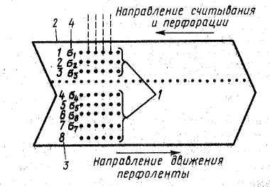
Figure 5- Eight-track punched tape
1 - code tracks; 2 - base edge; 3 – code track number; 4 - serial number of bits in the code combination
magnetic tape - a two-layer composition consisting of a plastic base and a working layer of powdered ferromagnetic material. Information is recorded on a magnetic tape in the form of magnetic strokes applied along the tape and located in the UE frame with a certain step corresponding to the specified IO speed. When reading the UE, the magnetic strokes are converted into control pulses. Each stroke corresponds to one pulse. Each impulse corresponds to a certain (discrete) movement of the IO; the length of this movement is determined by the number of pulses contained in the magnetic tape frame. Such a record of commands to move the IO called decoded .
Decoding is done using an interpolator , which converts the encoded geometric information about the contour of the workpiece entered into it (on a punched tape or from a computer) into a sequence of control pulses corresponding to elementary movements of the IO. The recording of the decoded program on magnetic tape is carried out on a special device, which includes: an interpolating device with an output intended for recording; tape drive mechanism with magnetic heads for erasing, recording and playback.
Information in the decoded form is recorded, as a rule, on a magnetic tape, and in the encoded form - on a punched tape or a punched card. Magnetic tapes are used in lathes with stepper motors that require a decoded view of the program.
Interpolation is the development of a program for the movement of the working body (tool), along the contour of the workpiece surface, successively in separate sections (frames).
Interpolator is a CNC block responsible for calculating the coordinates of the intermediate points of the trajectory that the tool must pass between the points specified in the NC. The interpolator has as input data a NC command for moving the tool from the start to the end point along the contour in the form of a straight line segment, a circular arc, etc.
To ensure the accuracy of trajectory reproduction of the order of 1 µm (the accuracy of the position sensors and the positioning accuracy of the caliper are about 1 µm), the interpolator generates control pulses every 5–10 ms, which requires high speed from it.
In order to simplify the algorithm of the interpolator, the given curvilinear contour is usually formed from segments of straight lines or from arcs of circles, and often the steps of movement along different coordinate axes are performed not simultaneously, but alternately. Nevertheless, due to the high frequency of issuing control actions and the inertia of the mechanical drive units, the broken trajectory is smoothed to a smooth curvilinear contour.
Interpolator, which is part of the CNC system, performs the following functions:
based on the numerical parameters of the section of the processed contour (coordinates of the start and end points of the straight line, the value of the radius of the arc, etc.) specified by the UE, it calculates (with a certain discreteness) the coordinates of the intermediate points of this section of the contour;
generates control electrical impulses, the sequence of which corresponds to the movement (at the required speed) of the executive body of the machine along the trajectory passing through these points.
In systems CNC is used mainly linear and linear-circular interpolators; the former ensure the movement of the tool between adjacent reference points along straight lines located at any angle, and the latter - both along straight lines and along arcs of circles.
Linear interpolation– sections between discrete coordinates are represented by a straight line located in space in accordance with the trajectory of the cutting tool.
Circular interpolation- provides for the representation of a section of the processing contour in the form of an arc of the corresponding radius. The capabilities of CNC devices make it possible to provide interpolation by describing a section of the contour with a complex algebraic equation.
Helical interpolation- a helix consists of two types of movements: circular in one plane and linear perpendicular to this plane. In this case, either the circular motion feedrate or the linear feedrate of the three used machine coordinates (axes) can be programmed.
The most important technical characteristic of the CNC system is her resolution or resolution .
discreteness- this is the minimum possible amount of movement (linear or angular) of the executive body of the machine, corresponding to one control pulse.
Most modern CNC systems have a resolution of 0.01 mm/pulse. Mastered in the production of systems with a resolution of 0.001 mm / pulse.
The CNC system practically replaces other types of control systems.
Classification of CNC systems
By technological capabilities and the nature of the movement of the working bodies CNC systems are divided into three groups:
Positional systems provide rectilinear movement of the executive body of the machine along one or two coordinates. The IO moves from position to position at the maximum speed, and its approach to the given position is at the minimum ("creeping") speed. Such CNC systems are equipped with drilling and coordinate boring machines.
contour systems are designed to perform working movements along a certain trajectory at a given speed according to the processing program. CNC systems that provide rectangular, rectilinear and curvilinear shaping belong to contour (continuous) systems, since they allow processing a part along a contour. In CNC systems with rectangular shaping, the IO of the machine moves along the coordinate axes alternately, so the tool path has a stepped form, and each element of this path is parallel to the coordinate axes. Number of controlled coordinates in such systems reaches 5 , a number of simultaneously controlled axes 4 . In CNC systems with rectilinear shaping, the movement of the tool during cutting along two coordinate axes (X and Y) is distinguished. In these systems, a two-coordinate interpolator is used, which issues control pulses to two feed drives at once. General number of controlled coordinates 2–5. CNC systems with curvilinear shaping allow you to control the processing of flat and three-dimensional parts containing areas with complex curvilinear contours. CNC contouring systems have a stepper motor. Such systems are equipped with turning, milling, boring machines.
Combined systems (universal) have the features of both positional and contour systems and are most typical for multi-purpose machines (drilling-milling-boring).
In machines with CNC systems, control is carried out from a program carrier, on which geometric and technological information is entered in numerical form.
In a separate group, machines with digital indication and a pre-set of coordinates are allocated. These machines have an electronic device for setting the coordinates of the desired points (preset of coordinates) and a cross table equipped with position sensors, which gives commands to move to the desired position. Wherein each current position of the table is displayed on the screen (digital indication) . In such machines, you can use a pre-set of coordinates or a digital indication; the initial work program is set by the machine operator.
In models of machine tools with PU, the letter F with a number is added to indicate the degree of automation:
F 1– machines with digital indication and presetting of coordinates;
F 2– machines with rectangular and positional CNC systems;
F 3– machines with contour rectilinear and curvilinear CNC systems;
F 4– machines with a universal CNC system for positional contouring.
In addition, the prefixes C1, C2, C3, C4 and C5 can be added to the designation of the CNC machine model, which indicates various models CNC systems used in machine tools, as well as various technological capabilities of machine tools. For example, the machine tool model 16K20F3S1 is equipped with the CNC system "Kontur 2PT-71", the machine tool model 16K20F3S4 is equipped with the CNC system EM907, etc.
For machines with cyclic systems PU entered in the model designation index C , With operational systems – index T (for example, 16K20T1). The CNC provides control of the movement of the working bodies of the machine and the speed of their movement during shaping, as well as the sequence of the processing cycle, cutting mode, and various auxiliary functions.
To characterize CNC machines, the following indicators are used:
Accuracy class :H- normal accuracy, P– increased accuracy, V– high precision, A– especially high precision, WITH– ultra-high precision (master machines);
Technological operations , performed on the machine : turning, drilling, milling, grinding, etc.;
Main parameters of the machine : for chucking machines – largest diameter installed product above the bed; for center and chuck machines- the largest diameter of the workpiece over the caliper; for bar-turning machine tools - the largest diameter of the processed bar; for milling and boring machine tools - overall dimensions (length, width) of the working surface of the table, the diameter of the working surface of the round rotary table; for drilling machine tools - the largest drilling diameter, the diameter of the retractable spindle, etc .;
The magnitude of the movement of the working bodies of the machine - a caliper in two coordinates, a table in two coordinates, a spindle assembly in linear and angular coordinates, etc.;
Discrete value (division price) minimum task of moving along the program (step);
Accuracy and repeatability of positioning by controlled coordinates ;
Main drive – type, nominal and maximum power values, spindle speed limits (stepped or stepless), number of operating speeds, number of automatically switched speeds;
Machine feed drive – coordinate, type, nominal and maximum moments, limits of working feed speeds and number of working feed speeds, rapid movement speed;
Number of tools - in the tool holder, turret, tool magazine;
Type of tool change – automatic, manual;
Overall dimensions of the machine and its weight .
According to the method of preparation and input of the control program distinguish:
operational CNC systems(in this case, the control program is prepared and edited directly on the machine, in the process of processing the first part from the batch or simulating its processing);
adaptive systems, for which the control program is being prepared, regardless of where the part is processed. Moreover, independent preparation of the control program can be performed either using computer technology that is part of the CNC system of this machine, or outside it (manually or using a programming automation system.)
According to the level of technical capabilities in international practice, the following designations of numerical control systems are accepted:
NC(Computer Numerical Control) - CNC;
HNC(Hand Numerical Control) - a kind of CNC device with setting a processing program by the operator from the remote control using keys, switches, etc .;
SNC(Speiher Numerical Control) - a CNC device that has a memory for storing the entire control program (the program is stored in internal memory);
CNC- CNC device allows you to control one CNC machine; the device corresponds to the structure of the control mini-computer or processor; expands the functionality of program control, it becomes possible to store the UE and edit it at the workplace, dialogue with the operator, wide possibilities for correction, the possibility of changing the program during its operation, etc.;
DNC(Direct Numerical Control) – systems more than high level, providing: control of a group of machines at once from a common computer; storage in memory of a very significant number of programs; interaction with auxiliary systems of the GPS (transportation, warehousing); selection of the start time for the processing of a particular part; accounting for operating time and equipment downtime, etc.
By the number of information streams CNC systems are divided into closed, open and adaptive.
Open systems are characterized by the presence of one stream of information coming from the reader to the executive body of the machine. In the mechanisms of such systems, stepper motors are used. It is a master device, the signals of which are amplified in various ways, for example, using a torque booster, the shaft of which is connected to the lead screw of the feed drive. In an open system, there is no feedback sensor and therefore there is no information about the actual position of the machine's actuators.
closed systems CNCs are characterized by two streams of information - from the reader and from the feedback sensor along the path. In these systems, the discrepancy between the given and actual values of the displacements of the executive bodies is eliminated due to the presence of feedback.
Adaptive Systems CNC are characterized by three streams of information: 1) from the reader; 2) from the feedback sensor along the way; 3) from sensors installed on the machine and controlling the processing process in terms of such parameters as wear of the cutting tool, changes in cutting and friction forces, fluctuations in the allowance and hardness of the workpiece material, etc. Such programs allow you to adjust the processing program taking into account real cutting conditions.
The use of a specific type of CNC equipment depends on the complexity of the manufactured part and the serial production. The smaller the serial production, the greater the technological flexibility the machine must have.
When manufacturing parts with complex spatial profiles in a single small-scale production, the use of CNC machines is almost the only technically justified solution. This equipment is also advisable to use if it is not possible to quickly make equipment. In serial production, it is also advisable to use CNC machines. Recently, autonomous CNC machines or systems of such machines have been widely used in conditions of reconfigured large-scale production.
The fundamental feature of the CNC machine is the work according to the control program (CP), on which the equipment operation cycle for processing a specific part and technological modes are recorded. When changing the part processed on the machine, you just need to change the program, which reduces the laboriousness of changeover by 80 ... 90% compared to the laboriousness of this operation on machines with manual control.
Main advantages of CNC machines:
the productivity of the machine is increased by 1.5….2.5 times compared to the productivity of similar machines with manual control;
the flexibility of universal equipment is combined with the accuracy and productivity of an automatic machine;
the need for skilled workers - machine operators is reduced, and the preparation of production is transferred to the field of engineering work;
parts made according to one program. They are interchangeable, which reduces the time of fitting work during the assembly process;
the terms of preparation and transition to the manufacture of new parts are reduced due to the preliminary preparation of programs, simpler and more versatile technological equipment;
the duration of the cycle of manufacturing parts is reduced and the stock of work in progress is reduced.
Control questions:
What is machine control software? What kinds of PU machine tools do you know?
What do CNC machines mean?
What is a CNC machine tool? What CNC systems do you know?
What is the fundamental feature of CNC machines?
List the main advantages of using CNC machines?
Coordinate axes and motion structures of CNC machines
For all CNC machines, a single coordinate notation system recommended by the ISO standard - R841: 1974 is used. Coordinates indicate the position of the axis of rotation of the machine spindle or workpiece, as well as rectilinear or circular movements of the tool or workpiece feed. In this case, the designation of the coordinate axes and the direction of movement in the machines are set so that the programming of processing operations does not depend on whether the tool or workpiece is moving or not. The basis is the movement of the tool relative to the coordinate system of the stationary workpiece.
The standard coordinate system is a right-handed rectangular system associated with the workpiece, the axes of which are parallel to the straight guides of the machine.
All rectilinear movements are considered in the coordinate system X , Y , Z . Circular motion with respect to each of the coordinate axes denoted by capital letters of the Latin alphabet : A, B, C (Figure 6). In all machines, the Z axis coincides with the axis of the spindle of the main movement, that is, the spindle that rotates the tool (in machines of the drilling-milling-boring group), or the spindle that rotates the workpiece (in machines of the turning group). If there are several spindles, the spindle perpendicular to the working surface of the table on which the workpiece is attached is chosen as the main one.
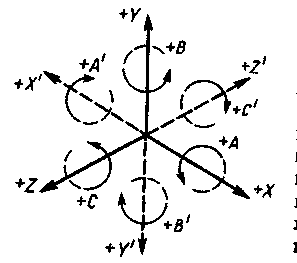
Figure 6- Standard coordinate system in CNC machines
Axis movement Z in a positive direction should match the direction removal of the tool from the workpiece . On drilling and boring machines, machining occurs when the tool is moved in the negative direction along the Z axis.
Axis X should preferably be horizontal and parallel to the workpiece mounting surface. On machines with a rotating workpiece (lathes), the X-axis movement is directed along the radius of the workpiece and parallel to the transverse guides. Positive axis movement X happens when the tool , installed in the main tool holder of the cross slide, moves away from the axis of rotation blanks.
On machines with rotating tools (milling, drilling) with a horizontal Z-axis positive axis movement X is directed to the right when viewed from the main tool spindle towards the workpiece. With a vertical Z-axis, positive movement along the X-axis to the right for single-column machines, and for two-column machines - from the main tool spindle to the left rack.
Positive axis direction Y should be chosen so that the Y-axis, together with the Z and X axes, forms a right-handed rectangular coordinate system. To do this, I use the rule of the right hand: the thumb is the X axis, the index finger is the Y axis, the middle finger is the Z axis ( drawing).
If, in addition to the main (primary) rectilinear movements along the X, Y and Z axes, there are secondary movements parallel to them, then they are designated U, V, W, respectively. If there are tertiary movements, they are designated P, Q and R.
Primary, secondary and tertiary movements of the working bodies of the machine are determined depending on the distance of these bodies from the main spindle.
Secondary rotational movements, whether or not parallel to the axes A, B, and C, are designated D or E.
Methods and origin of coordinates
When setting up a CNC machine, each executive body is set to a certain initial position, from which it moves during the processing of the workpiece at strictly defined distances. This allows the tool to pass through the defined reference points of the path. The magnitude and direction of movement of the executive body from one position to another are set in the UE and can be performed on the machine in different ways, depending on the design of the machine and the CNC system. In modern CNC machines, two methods of counting displacements are used: absolute and relative (in increments).
Absolute way of counting coordinates – the position of the origin of coordinates is fixed (stationary) for the entire workpiece processing program. When compiling the program, the absolute values of the coordinates of successively located points, specified from the origin, are recorded. When processing a program, the coordinates are each time counted from this origin, which eliminates the accumulation of displacement errors in the process of processing the program.
Relative way of counting coordinates – the position of the executive body, which it occupies before starting to move to the next reference point, is taken as the zero position each time. In this case, increments of coordinates are written into the program for sequential movement of the tool from point to point. This reference method is used in CNC contouring systems. The positioning accuracy of the executive body at a given reference point is determined by the accuracy of processing the coordinates of all previous reference points, starting from the initial one, which leads to the accumulation of movement errors during program processing.
For the convenience of programming and setting up CNC machines, in some cases, the origin of coordinates can be selected anywhere within the strokes of the executive bodies. This origin of coordinates is called floating zero" and is used mainly on drilling and boring machines equipped with CNC positioning systems.
Development of control programs
When developing a control program, it is necessary:
to design a route processing technology in the form of a sequence of operations with a choice of cutting and auxiliary tools and devices;
to develop an operating technology with the calculation of cutting conditions and the determination of the trajectories of the movement of cutting tools;
determine the coordinates of reference points for the trajectories of the cutting tools;
draw up a settlement and technological map and a map for setting up a machine;
encode information;
put information on the program carrier and send it to the memory of the CNC machine or manually type it on the control panel of the CNC device;
check and, if necessary, correct the program.
For programming, you need a drawing of the part, a machine manual, programming instructions, a catalog of cutting tools and cutting data standards.
According to GOST20999-83, the program elements are written in a certain order as a sequence of frames and using the corresponding symbols (see table 1).
Table 1 Meanings of control characters and signs
|
Symbol |
Meaning |
|
Angle of rotation about the X-axis |
|
|
Angle of rotation around the Y-axis |
|
|
Angle of rotation around the Z axis |
|
|
The second function of the tool |
|
|
Second feed function |
|
|
First function (speed) feed |
|
|
preparatory function |
|
|
Tool length offset |
|
|
Angular interpolation parameter or thread lead parallel to the X axis |
|
|
Angular interpolation parameter or thread lead parallel to Y-axis |
|
|
Angular interpolation parameter or thread lead parallel to the Z axis |
|
|
Helper function |
|
|
Frame number |
|
|
Tertiary length of travel parallel to the X axis |
|
|
Tertiary length of movement parallel to the Y axis |
|
|
Rapid travel along the Z axis or tertiary length of travel parallel to the Z axis |
|
|
Function (speed) of the main movement |
|
|
First tool function |
|
|
Secondary travel length, parallel to the X axis |
|
|
Secondary travel length, parallel to the Y axis |
|
|
Secondary travel length, parallel to the Z axis |
|
|
Primary travel length, parallel to the X axis |
|
|
Primary travel length, parallel to the Y axis |
|
|
Primary travel length, parallel to the Z axis |
|
|
Symbol indicating the end of the block of the control program |
|
|
Sign indicating the beginning of the control program |
|
|
mathematical sign |
|
|
mathematical sign |
|
|
Decimal sign |
Program block (phrase)- a sequence of words arranged in a certain order and carrying information about one technological work operation (Figure 8).
Program Word- a sequence of characters that are in a certain connection as a whole.
Figure 8– Program block
Each block of the control program must contain:
the word "Frame number";
information words or a word (it is allowed not to use);
symbol "End of frame";
tab character (may not be used). When using these symbols, they are placed before each word in the UE frame, except for the word "Frame number".
the word (or words) "Preparatory function";
the words "Dimensional movements", which are recommended to be written in the following sequence of characters: X, Y, Z, U, V, W, P, Q, R, A, B, C;
the words "Interpolation parameter" or "Thread pitch" I, J, K;
the word (or words) "Feed function", which refer only to a specific axis and must immediately follow the words "Dimensional movement" along that axis; the word "feed function", referring to two or more axes, must follow the word "Dimensional movement";
the word "Function of the main movement";
the word (or words) "Tool function";
the word (or words) "Auxiliary function".
The order and multiplicity of writing words with addresses D, E, H, U, V, W, P, Q, R, used in values other than those accepted, are indicated in the form of a specific CNC device.
Within one UE block, the words "Dimensional displacements" and "Interpolation parameter" or "Thread pitch" should not be repeated; the words "Preparatory function", included in the same group, should not be used.
After the symbol "Main frame" (:), the UE must contain all the information necessary to start or resume processing. This character is used to identify the start of a program on a data carrier.
Each word in the NC frame must consist of an address symbol (capital letter of the Latin alphabet according to the table), a mathematical sign "+" or "-" (if necessary), a sequence of numbers.
Words in NC can be written in one of two ways: without the use of a decimal point (the position of the decimal point is implied) and with its use (the explicit position of the decimal point). An explicit decimal point is indicated by the symbol "DS". The implied position of the decimal point must be defined in the specifications of the particular CNC.
When writing words using a decimal point, words that do not have a decimal point must be treated by the CNC as integers. In this case, non-significant zeros before and (or) after the sign can be omitted: X.03 means the size is 0.03 mm along the X axis; X1030 - size 1030.0 mm along the X axis.
Currently, when programming, the address method of recording information on punched tape is more often used. The information of each frame is divided into two types: 1) a letter (address), indicates the executive body of the CNC system (or machine), to which the command is given; 2) the number following the address and indicating the amount of movement of the executive body of the machine (with the sign “+” or “-”) or a code entry (for example, the amount of feed, etc.). The letter followed by the number is the word. A program block consists of one, two or more words.
Encoded recording of a number of UE frames for processing the workpiece on lathe may look like this:
No. 003 X +000000 - moving the cutter to the zero point along the X axis;
№ 004 Z +000000 - moving the cutter to the zero point along the Z axis;
No. 005 G26 - command to work in increments
No. 006 G10 X -006000 - G10 - linear interpolation (rectilinear
travel path)
No. 007X-014000 F10080
No. 008 Z +000500 F10600
No. 009 X +009500 F70000
No. 010 X +002000 Z -001000 F10100
………………………………………………………..
…………………………………………………………….
No………M102
The numbers after the letters determine the number of digits of the numerical part of the given word. Address brackets X,Z,I,K indicate possible digits of numbers expressing geometric information when various modes CNC work. This information is recorded as the number of pulses (the number of millimeters of IO movement divided by the discreteness of their processing).
Word (or words ) "Preparatory function" must be expressed as a code symbol in accordance with Table 2.
Table 2 - Preparatory functions
|
Designation functions |
Function value |
|
Positioning. Moving at high speed to a given point. Previously set cutting feed is not canceled |
|
|
Linear interpolation. Traverse with programmed feed in a straight line to a point |
|
|
Circular interpolation respectively in the direction and counter-clockwise direction |
|
|
Delay in processing for a certain time, which is set from the control panel or in the frame |
|
|
Temporary stop. The duration of the stop is not limited. The machine is activated by pressing a button |
|
|
parabolic interpolation. Parabolic movement with programmed feed |
|
|
Overclocking Smooth increase in feed rate to its programmed value at the beginning of the movement |
|
|
Braking at the end of the frame. Smooth decrease in feedrate to a fixed value |
|
|
Interpolation planes respectively XY,XZ,YZ |
|
|
Threading with constant, increasing and decreasing pitch, respectively |
|
|
Canceling a tool offset specified by one of the G41-G52 functions |
|
|
Tool diameter or radius compensation in contouring control. The cutting tool is located respectively to the left and right of the part |
|
|
Tool diameter or tool radius offset respectively positive and negative |
|
|
Tool diameter or radius offset in straight shaping: G45+/+, G46+/-, G47-/-, G48-/+, G49 0/+, G50 0/-, G51 +/0, |
|
|
Cancel a linear shift specified by one of the functions G54-G59 |
|
|
Linear shift along coordinates X,Y,Z and in the XY,XZ,YZ planes, respectively |
|
|
Tapping |
|
|
Canned cycle cancellation specified by one of the functions G81-G89 |
|
|
Constant cycles |
|
|
Absolute size. Counting movements in the absolute coordinate system with the origin at the zero point of the CNC |
|
|
Size in increments. Counting movements relative to the previous programmed point |
|
|
Setting absolute position accumulators |
|
|
Feedrate in reverse of time |
|
|
Feed unit per minute and per revolution respectively |
|
|
Cutting speed unit (m/min) |
|
|
Main motion unit (rpm) |
Note: G07, G10-G16, G20, G32, G36-G39, G60-G62, G64-G79, G98, G99 are reserved codes.
All dimensional movements must be specified in absolute values or increments. The control method must be selected by one of the preparatory functions: G90 (absolute size) or G91 (incremental size ).
The address of each word "Dimensional movement" is followed by two digits, the first of which shows the number of digits before the implied decimal point separating the integer part of the number from the fractional, the second - the number of digits after the decimal point. If it is possible to omit the zeros before the first significant digit and after the last in the words "Dimensional Movements", the address "Dimensional Movement" must be followed by three digits. If zeros are omitted before the first significant digit, then the first digit must be zero. If zeros are omitted after a significant digit, the last digit must be zero.
All linear movements must be expressed in millimeters and their decimal fractions. All angular dimensions are given in radians or degrees. Expression of angular dimensions in decimal fractions of a revolution is allowed.
If the CNC allows dimensions to be specified in absolute values (positive or negative) depending on the origin of the coordinate system, then the mathematical sign ("+" or "-") is an integral part of the word "Dimensional movement" and must precede the first digit of each dimension.
If the absolute dimensions are always positive, then no sign is put between the address and the number following it, and if they are either positive or negative, then the sign is put.
If the CNC allows incremental dimensions, then a mathematical sign must precede the first digit of each dimension to indicate the direction of movement.
The movement of the tool along a complex trajectory is provided special device- an interpolator. Interpolation of linear and arc segments is performed separately for sections of a given trajectory. Each of the sections can be recorded in one or more frames of the control program.
The functional nature of the interpolated section of the trajectory (straight line, circle, parabola or curve of a higher order) is determined by the correspondingpreparatory function (G01 - G03, G06). To set interpolation optionsapply addresses I, J, K, using them to determine the geometric characteristics of curves (for example, the center of an arc of a circle, radii, angles, etc.). If a mathematical sign ("+" or "-") is to be written along with the interpolation parameters, it must follow the address character and before the numeric characters. If the sign is absent, then the "+" sign is assumed.
The start point of each interpolation section coincides with the end point of the previous section, so it is not repeated in the new block. Each subsequent point lying on this interpolation section and having certain coordinates corresponds to a separate frame of information with the addresses of the movements X, Y or Z.
Modern CNCs have "built-in" functions in their software to perform the simplest interpolation. So, in CNC lathes, the chamfer at an angle of 45 ° is given by the address WITH with a sign and a final size along the coordinate along which the part is processed before chamfering. The sign under the address WITH must match the sign of processing along the X coordinate (figure, a). The direction along the Z coordinate is set only in the negative direction.
To specify an arc, the coordinates of the end point of the arc and the radius under the address R are specified with a positive sign when machining clockwise and a negative sign when machining counterclockwise (Figure 9).
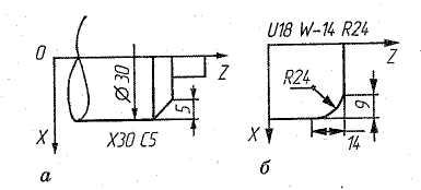
Figure 9- Programming chamfers (a) and arcs (b) on a CNC lathe
The feed and speed of the main movement are encoded by numbers, the number of digits of which is specified in the format of a specific CNC device. Choicefeed type G93 (feed in reverse time function), G94 (feed per minute), G95 (feed per revolution).
Choicetype of main movement must be carried out by one of the preparatory functions:G96 (constant cutting speed) or G97 (rpm).
The direct notation method is used as the main method of encoding the feed, at which the following units should be used: millimeter per minute - the feed does not depend on the speed of the main movement; millimeter per revolution - the feed depends on the speed of the main movement; radians per second (degrees per minute) - feed refers to circular motion only. When directly coding the speed of the main movement, the number indicates the angular speed of the spindle(radians per second or revolutions per minute) or cutting speed (in meters per minute). For example, if the program specifies the spindle speed as S - 1000, this means that the spindle rotates clockwise at a speed of 1000 rpm.(If there is no minus, then the spindle is rotating counterclockwise).
The word "Tool function" is used to select the tool . It can be used to correct (or compensate) the tool. In this case, the word "Tool function" will consist of two groups of numbers. The first group is used to select a tool, the second group is used for correction. If a different address is used to write the tool offset (compensation), it is recommended use the symbol D or H.
Number of digits following addresses T, D and H , is specified in the format of a specific CNC device.
Word (or words) "Help Function" expressed as a code number in accordance with Table 3.
Table 3 - Auxiliary functions
|
Designation functions |
Function value |
|
Programmed stop. Stop spindle, feed and turn off cooling |
|
|
Stop with confirmation. The same as M 00, but is performed by first pressing the corresponding button on the operator's console |
|
|
End of program. Spindle stop and coolant off |
|
|
Spindle rotation respectively clockwise and counterclockwise |
|
|
Spindle stop most effective way |
|
|
Tool change. Tool change command is given manually or automatically |
|
|
Turning on cooling, respectively No. 2 and No. 1 |
|
|
Turn off cooling. Cancels commands M07, M08, M50, M51 |
|
|
Clamp and unclamp. Applies to clamping devices machine tables, blanks, etc. |
|
|
Spindle rotation in the direction and counterclockwise while turning on the cooling |
|
|
Fast travel to "+" and "-" |
|
|
End of program for CNC with built-in memory |
|
|
Spindle stop at a certain angular position |
|
|
End of program, which is a repeatedly read program chapter |
|
|
End of information |
|
|
Block bypass. Command to temporarily cancel the lock |
|
|
Feed range, respectively, No. 1 and No. 2 |
|
|
Spindle rotation range respectively No. 1 and No. 2 |
|
|
Cancel M 49 |
|
|
Cancel manual override |
|
|
Cooling off, respectively No. 3 and No. 4 |
|
|
Tool linear offset in position #1 and #2 respectively |
|
|
Cancel M 59 |
|
|
Constant spindle speed |
|
|
Workpiece change |
|
|
Linear displacement of the workpiece to a fixed position 31 and No. 2, respectively |
|
|
Clamping and squeezing the workpiece |
|
|
Table clamping and wringing |
The thread pitch value must be expressed in millimeters per spindle revolution. The number of digits in the words that define the thread pitch is defined in the format of a specific CNC device. When cutting a thread with a variable pitch, the words under addresses I and K must specify the dimensions of the initial thread pitch.
The word "Feed function" must not be programmed with a constant thread pitch.
Each control program must begin with the symbol "Start of the program", after which there must be the symbol "End of block", and then a block with the corresponding number. If it is necessary to designate the control program, this designation (number) must be located immediately after the symbol "Start of the program" before the symbol "End of block".
The control program must end with the symbol "End of program" or "End of information". Information placed after the "End of Information" symbol is not accepted by the CNC. Before the symbol "Beginning of the program" and after the symbol "End of the program" and "End of information" on the punched tape, it is recommended to leave sections with the PUS symbol ("Empty").
Debugging and correcting the program
When preparing a control program, an important point is the development cutting tool paths relative to the part and on this basis - a description of the movements of the corresponding organs of the machine. For this, several coordinate systems are used.
Main settlement system – machine coordinate system , which defines the limiting displacements and positions of its working bodies. These positions are characterized base points , which are selected depending on the design of the machine . for instance, for spindle assembly the base point is the point of intersection of the end face of the spindle with the axis of its rotation, for the cross table is the intersection point of its diagonals, for turntable- the center of rotation on the mirror of the table, etc. The position of the axes and their directions in the standard coordinate system are discussed above.
The origin of the standard coordinate system is usually aligned with the base point of the node that carries the workpiece. In this case, the assembly is fixed in a position in which all movements of the working bodies of the machine occur in a positive direction.(Figure 10). From this base point,called zero machine tool , the position of the working bodies is determined, if information about their position is lost (for example, due to an emergency power outage). The working bodies are moved to the zero of the machine by pressing the corresponding buttons on the control panel or using the commands of the control program. Precise stop of the working bodies in the zero position for each of the coordinates is provided by zero position sensors. For example, when turning, the zero of the machine is set with an offset to avoid an accident.
Workpiece coordinate system with a base point, is considered when fixing the workpiece on the machine, to determine the position of this system and the machine coordinate system relative to each other (Figure 9). Sometimes this connection is made using the base point of the fixture.
Tool coordinate system is designed to set the position of its working part relative to the mount. The tool is described in the working position assembled with the holder. In this case, the axes of the tool coordinate system are parallel to the corresponding axes of the standard machine coordinate system and directed in the same direction. The base point is taken as the origin of the tool coordinate system tool block selected taking into account the features of its installation on the machine.
The position of the tool tip is given by the radius r and the X and Z coordinates of its setting point. This point is usually used when defining a toolpath whose elements are parallel to the coordinate axes. With a curved trajectory, the center of rounding at the tool tip is taken as the design point. The relationship between the coordinate systems of the machine, workpiece and tool is easy to follow in Figure 9.
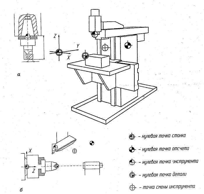
Figure 9- Coordinate systems of the part when processing on milling (a) and turning (b) CNC machines
When developing a control program and processing a part use the program coordinate system. Its axes are parallel to the machine coordinate axes and directed in the same way.
The origin of coordinates (the starting point of the machine) is chosen based on the convenience of measuring dimensions. To avoid significant idle moves, the starting position from which machining starts and in which tools and workpieces are changed is set so that the tools are as close as possible to the workpiece.
For "binding" in the space of the machine displacement measurement system, a zero (base) reference point is used. Each time the machine is switched on, this point “links” the measuring system to the machine zero point.
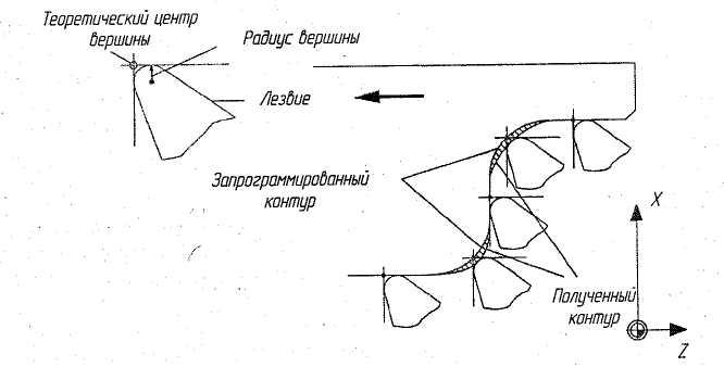
When changing cutting tools during the processing of parts, a discrepancy between the processing results and the requirements for it may occur (loss of accuracy, increase in roughness, vibration, etc.). In this case, you need to promptly correct the program. Machining errors that require correction may occur when drilling holes, turning conical and shaped surfaces due to the presence of a tip radius in the cutters.
Two types of compensation are possible - for the length and for the radius of the tool.
In the first case, the correction of the length of the drill or the overhang of the cutter holder is carried out using Team H with a set of numbers corresponding to the correction value. For instance, frame N 060 T 02 H 15
Indicates the introduction of a length offset of 15 mm for tool No. 2.
The second case provides tool radius correction and is due to the fact that when turning conical and shaped surfaces when milling contours, the trajectory of the center of the radius surface of the tool must be equidistant relative to the shape of the surface (Figure 11).
Here is a fragment of the program for compensation of the cutter radius:
|
N 035 G 81 X +25 Z +4 I +7 ………………………………………………………. Description of the machining loop ………………………………………………………. |
Figure 11- Cutter radius compensation |
A fragment of the program, providing for milling along the equidistant (Figure 12)
N 005 G 90 G 00 X 0 Y 0 S 1000 T01 M 03
N 006 G 41 G 01 X 220 Y 100 F 100
N 007 X 220 Y 430 F 50
N 008 G 02 G 17 X 370 Y 580 I 370 J 430
N 009 G 01 X 705 Y 580
N 010 X 480 Y 190
N 011 X 220 Y 190
N 012 G 00 X 0 Y 0 05M
Function G 41 (cutter diameter compensation if the cutter is to the left of the workpiece) in block N 006 ensures that the center of the cutter moves equidistantly with respect to the surface to be machined.
In some cases, it is necessary to adjust the feed in order to reduce the roughness of the machined surface, eliminate vibrations, etc. To do this, it is necessary to set a new feed value on the control panel and enter it into the memory of the CNC device.
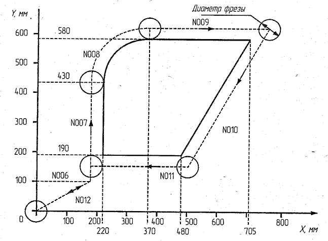
Figure 12- Cutter movement equidistant when milling an external contour
Design features of CNC machines.
CNC machines have advanced technological capabilities while maintaining high reliability. The design of CNC machines should, as a rule, ensure the combination various kinds processing (turning - milling, milling - grinding), ease of loading workpieces, unloading parts (which is especially important when using industrial robots), automatic or remote control of interchangeable tools, etc.
An increase in machining accuracy is achieved by high manufacturing accuracy and machine rigidity, which exceeds that of a conventional machine for the same purpose. Why do they reduce the length of its kinematic chains: they will change autonomous drives, if possible, reduce the number of mechanical gears. The drives of CNC machines must also provide high speed.
Improving accuracy is also facilitated by the elimination of gaps in the transmission mechanisms of feed drives, and the reduction of friction losses of guides and other mechanisms. Improving vibration resistance, reducing thermal deformations, using feedback sensors in machine tools. To reduce thermal deformations, it is necessary to ensure a uniform temperature regime in the machine mechanisms, which, for example, is facilitated by the preheating of the machine and its hydraulic system. The temperature error of the machine can also be reduced by introducing a correction into the feed drive from the temperature sensor signals.
Base parts (beds, columns, bases) are made more rigid by introducing additional stiffeners. Movable bearing elements (calipers, tables, skids) also have increased rigidity. Tables, for example, are constructed in a box shape with longitudinal and transverse shapes. Base parts are cast or welded. There has been a tendency to make such parts from polymer concrete or synthetic granite, which further increases the rigidity and vibration resistance of the machine.
The guides of CNC machines have high wear resistance and low friction force, which makes it possible to reduce the power of the servo drive, increase the accuracy of movements, and reduce the mismatch of the servo system.
To reduce the coefficient of friction, the sliding guides of the frame and caliper are created in the form of a sliding pair "steel (or high-quality cast iron) - plastic coating (fluoroplast, etc.)"
Rolling guides have a high durability, are characterized by low friction, and the coefficient of friction is practically independent of the speed of movement. Rollers are used as rolling elements. The preload increases the rigidity of the guides by 2 .. 3 times; adjusting devices are used to create the preload.
Drives and converters for CNC machines. In connection with the development of microprocessor technology, converters are used for feed and main movement drives with full microprocessor control - digital converters or digital drives. Digital drives are electric motors that run on direct or alternating current. Structurally, frequency converters, servo drives and main start and reverse devices are separate electronic control units.
Feed drive for CNC machines. As a drive, motors are used, which are synchronous or asynchronous machines controlled by digital converters. Non-collector synchronous (valve) motors for CNC machines are made with a permanent magnet based on rare earth elements and equipped with feedback sensors and brakes. Asynchronous motors are used less frequently than synchronous motors. The feed motion drive is characterized by the minimum possible gaps, short acceleration and deceleration times, and large friction forces, reduced heating of the drive elements, and a large control range. Ensuring these characteristics is possible due to the use of ball and hydrostatic screw gears, rolling guides and hydrostatic guides, without backlash gearboxes with short kinematic chains, etc.
Main motion drives for CNC machines are usually motors alternating current– for high powers and direct current – for low powers. The drives are three-phase four-pole asynchronous motors that perceive large overloads and operate in the presence of metal dust, chips, oil, etc. in the air. therefore, an external fan is provided in their design. Various sensors are built into the engine, such as a spindle position sensor, which is necessary for orientation or providing an independent coordinate.
Frequency converters for controlling asynchronous motors have a control range of up to 250. The converters are electronic devices built on the basis of microprocessor technology. Programming and parameterization of their work is carried out from built-in programmers with a digital or graphic display. Control optimization is achieved automatically after entering the motor parameters. The software includes the ability to configure the drive and put it into operation.
Spindles of CNC machines are made more precise, rigid, with increased wear resistance of the necks, seating and locating surfaces. The design of the spindle is much more complicated due to the built-in devices for automatic unclamping and clamping of the tool, sensors used in adaptive control and automatic diagnostics.
Spindle supports must ensure the accuracy of the spindle for a long time in variable operating conditions, increased rigidity, and small temperature deformations. The accuracy of spindle rotation is ensured primarily by the high precision manufacturing of the bearings.
Most often in the bearings of the spindles I use rolling bearings. To reduce the influence of clearances and increase the rigidity of the supports, bearings are usually installed with a preload or the number of rolling elements is increased. Plain bearings in spindle bearings are used less frequently and only if there are devices with periodic (manual) or automatic clearance adjustment in the axial or radial direction. In precision machines, aerostatic bearings are used, in which compressed air is located between the shaft neck and the bearing surface, which reduces wear and heating of the bearing, increases rotation accuracy, etc.
The positioning drive (i.e. moving the working body of the machine to the required position according to the program) must have high rigidity and ensure smooth movement at low speeds, high speed of auxiliary movements of the working bodies (up to 10 m / min and more).
The auxiliary mechanism of CNC machine tools includes tool changers, chip removal, lubrication system, clamping devices, loading devices, etc. this group of mechanisms in CNC machines differs significantly from similar mechanisms used in conventional universal machines. For example, as a result of an increase in the productivity of CNC machines, there was a sharp increase in the descending chips per unit time, and hence the need arose to create special devices for removing chips from the processing zone. To reduce the loss of time during loading, devices are used that allow you to simultaneously install the workpiece and remove the part during the processing of another workpiece.
Devices for automatic tool change (magazines, auto-operators, turrets) must ensure minimum time spent on tool change, high reliability in operation, stability of the tool position, i.e. the constancy of the overhang size and the position of the axis during repeated tool changes, to have the necessary capacity of the magazine or turret.
The turret is the simplest tool changer: the installation and clamping of the tool is carried out manually. In the working position, one of the spindles is driven by the main drive of the machine. Turrets are installed on turning, drilling, milling, CNC multi-purpose machines; from 4 to 12 tools are fixed in the head.
Control questions:
What are the main design features CNC machines.
List the design features of the base parts, drives of the main movement and feed movement, as well as auxiliary mechanisms of CNC machines.
CNC lathes.
CNC lathes are designed for outdoor and internal processing complex workpieces such as bodies of revolution. They make up the largest product group in the CNC machine park. On CNC lathes, a traditional set of technological operations is performed: turning, cutting, drilling, threading y and others.
The classification of CNC lathes is based on the following features:
location of the spindle axis (horizontal and vertical machines);
the number of tools used in the work (one - and many - tool machines);
ways of fixing them (on the caliper, in the turret, in the tool magazine);
type of work performed (center, cartridge, cartridge-center, carousel, bar machines;
degree of automation (semi-automatic and automatic).
CNC center machines are used for processing workpieces such as shafts with rectilinear and curvilinear contours. On these machines, you can cut the thread with a cutter according to the program.
Cartridge tanks with CNC are designed for processing, drilling, reaming, countersinking, countersinking, tapping in axial holes of parts such as flanges, gears, covers, pulleys, etc.; it is possible to cut the internal and external thread by program.
CNC chuck center machines are used for external and internal processing of various complex workpieces such as hoist of rotation and have the technological capabilities of center turning and chuck machines.
Carousel CNC machines are used to process workpieces of complex bodies.
CNC lathes (Figure 12) are equipped with turrets or a tool magazine. Turrets are 4-, 6- and twelve-position, and each position can be equipped with two tools for external and internal processing of the workpiece. The axis of rotation of the head can be parallel to the spindle axis, perpendicular to it or obliquely.
When two turrets are installed on the machine, tools for external processing are fixed in one of them (1), and tools for internal processing are fixed in the other (2) (see Figure 13). Such heads can be located coaxially with respect to one another or have a different arrangement of axes. Indexing of turrets is usually carried out by using hardened and ground flat-toothed face couplings, which provide high accuracy and rigidity of indexing of the head. Interchangeable interchangeable tool blocks are installed in the grooves of the turrets, which are adjusted to the size outside the machine, on special devices, which significantly increases the productivity and accuracy of processing. The cutting blocks in the turret are based either on a prism or with the help of cylindrical shanks 6 (Figure 14). The cutter is fixed with screws through the clamping bar 3. To set the cutter along the height of the centers, a lining 2 is used. Two adjusting screws 5, located at an angle of 45 ° to one another, make it possible to bring the top of the cutter to the specified coordinates during adjustment. The supply of coolant to the cutting zone is carried out through a channel in the body 1, ending with a nozzle 4, which allows you to adjust the direction of the coolant supply.
Tool magazines (capacity 8…20 tools) are rarely used, since practically no more than 10 tools are required for turning one workpiece. The use of a large number of tools is advisable in cases of turning hard-to-cut materials, when the tools have a short tool life.
The expansion of the technological capabilities of lathes is possible due to the erasure of the line between lathes and milling machines, the addition of off-center drilling, contour milling (that is, the spindle rotation is programmed); in some cases, threading of misaligned workpiece elements is possible.
Control questions:
How are CNC lathes classified according to the type of work performed?
What tool holders are used on CNC lathes?
How are the cutting blocks based in the turret of the machine?
CNC milling machines
CNC milling machines are designed for processing flat and spatial surfaces of workpieces of complex shape. The designs of CNC milling machines are similar to those of traditional milling machines, the difference from the latter lies in the automation of movements along the NC during shaping.
The classification of CNC milling machines is based on the following features:
Spindle location (horizontal and vertical);
The number of coordinate movements of the table or milling headstock;
Number of tools used (single-tool and multi-tool);
How to install tools in the machine spindle (manually or automatically).
By layout milling machines CNC machines are divided into four groups:
vertically - milling machines with a cross table;
console milling machines;
longitudinally - milling machines;
wide-purpose tool machines.
In vertical milling machines with a cross table (Figure 15, a), the table moves in the longitudinal (X axis) and transverse (Y axis) horizontal directions, and the milling head moves in the vertical direction (Z axis).
In console milling machines (Figure 15, b), the table moves along three coordinate axes (X, Y and Z), and the headstock is not movable.
In longitudinal milling machines with a movable crossbar (Figure 15, c), the table moves along the X axis, the spindle head - along the Y axis, and the transverse headstock along the Z axis. In longitudinal milling machines, with a fixed cross member (Figure 15, d), the table moves along the X axis, and the headstock along the Y and Z axes.
In universal tool milling machines (Figure 15,e), the table moves along the X and Y axes, and the headstock moves along the Z axis.
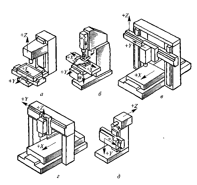
Figure 15 – Coordinate system in various modifications of milling machines:
a) - a milling machine with a cross table; b) console milling machine; c) longitudinal milling machine with a movable cross member; d) longitudinal milling machine with a fixed crossbar; e) wide universal milling machine.
Milling machines are mainly equipped with rectangular and contour CNC devices.
With rectangular control ( symbol in the machine model - Ф 2) the machine table moves in a direction parallel to one of the coordinate axes, which makes it impossible to process complex surfaces. Machines with rectangular control are used for milling planes, bevels, ledges, grooves, bosses of different heights and other similar surfaces.
With contour control (symbol in the machine model - F 3 and F 4), the trajectory of the table is more complex. Machines with contour control are used for milling various cams, dies, molds and other similar surfaces. The number of controlled coordinates is usually three, and in some cases four or five. With contour control of motion, shaping is performed at least along two coordinate axes simultaneously.
In some cases, CNC systems are also used on milling machines when processing simple-shaped workpieces in medium and large-scale production.
In CNC milling machines, asynchronous electric motors (in these cases there is a gearbox) or DC electric motors are used as the drive of the main movement.
On small milling machines with rectangular CNC, one DC drive motor and a gearbox with automatically switched electromagnetic clutches are used, and on heavy machines with contour control, each controlled coordinate movement is carried out from an automatic DC electric drive.
Feed movement drives of CNC milling machines have short kinematic chains that transmit movements from the engine directly to the executive body.
Consider the device of a cantilever vertical milling machine mod. 6R13F3. This machine is a cantilever, i.e. his table has a working movement in the horizontal plane (along the X and Y coordinates) and (together with the console) an installation movement in the vertical direction (along the W coordinate); working movement along the Z coordinate has a slider with a spindle. Bed 8 is the base on which the units and mechanisms of the machine are mounted. At the front, the frame has vertical guides covered with a casing 9, along which the console 1 moves. Slides 2 are mounted on the horizontal guides, along the longitudinal guides of which the table 3 moves. In accordance with safety requirements, the slider has a protective shield 4. Behind the machine is a cabinet 10 with electrical equipment and CNC.
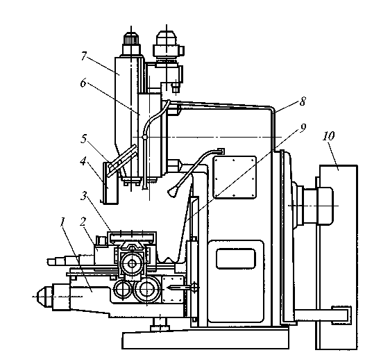
Figure 16 - Vertical milling machine mod. 6R13F3:
1-console; 2-sled; 3-table; 4-protective shield; 5-spindle: 6-milling headstock; 7-slider; 8-bed; 9-casing;
10-cabinet with electrical equipment.
Control questions:
What layouts of CNC milling machines do you know?
What CNC systems are equipped with milling machines?
CNC drilling machines
Vertical - CNC drilling machines, unlike similar machines with manual control, are equipped with cross tables that automatically move the workpiece along the X and Y axes, as a result of which there is no need for conductors or its preliminary marking.
CNC radial drilling machines have a column movable along the X axis, a sleeve movable along the Y axis with a spindle head, in which a drilling spindle is mounted, moving along the Z axis. In addition, the sleeve can move in the vertical direction when applied.
Automated movements of the working bodies of drilling machines along the X and Y axes ensure the execution of holemaking and milling.
Drilling machines are equipped with positional CNCs that allow you to automatically set the working bodies to the position specified by the program. The cutting tool on CNC drilling machines is fixed directly in the conical bore of the spindle or with the help of intermediate bushings and mandrels.
A general view of the vertical drilling machine model 2R135F2 - 1, equipped with CNC, is shown in Figure 17. On the basis of the machine 1, a column 10 is mounted, along the rectangular vertical guides of which the caliper 4 moves, carrying the turret 3. Gearboxes 5 and the feed reducer are mounted on the column 10 6. Slides 2 of the cross table move along the horizontal guides of the base 1, and the upper part 11 of the table moves along the guides of the sled. On the right side of the machine there is a cabinet 8 with electrical equipment and a CNC 9. The machine has a pendant 7 control panel.
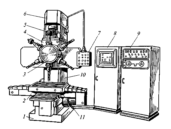
Figure 17 – Vertical drilling machine model 2R135F2:
1-base; 2-sled; 3-turret; 4- support; 5-speed box; 6-feed reducer; 7-pendant console; 8- cabinet with electrical equipment; 9-CNC; 10-column; 11-top of the table.
Control questions:
What is the fundamental difference between vertically drilling machines CNC or non-CNC?
What CNC systems are equipped with vertically - drilling machines?
CNC grinding machines
The CNC system is equipped with surface grinding, round - and centerless grinding and other machines. When creating CNC grinding machines, technical difficulties arise, which are explained by the following reasons. The grinding process is characterized, on the one hand, by the need to obtain high accuracy and surface quality with minimal size dispersion, on the other hand, by a feature that consists in the rapid loss of dimensional accuracy of the grinding wheel due to its intense wear during operation. In this case, the machine requires mechanisms for automatic compensation of wear of the grinding wheel. The CNC must compensate for distortions of the LED system, temperature errors, differences in workpiece allowances, machine errors when moving along coordinates, etc. Measuring systems must have a resolution that provides tight tolerances for positioning accuracy. For example, in circular grinding machines, such devices provide continuous measurement of the diameter of the workpiece during processing with a relative error of no more than 2 × 10 -5 mm. The control of the longitudinal movements of the table is carried out with an error of not more than 0.1 mm.
For grinding machines, CNC-type systems with control over three to four coordinates are used, but in machines that work with several circles, control over five, six and even eight coordinates is possible. The relationship between the operator and the CNC system of the grinding machine is in most cases carried out interactively using the display. The control system uses built-in diagnostic systems that increase the reliability of the machines.
CNC circular grinding machines are the most common, giving the maximum effect when processing multi-stage parts such as spindles, shafts of electric motors, gearboxes, turbines, etc. from one installation. Productivity is increased mainly as a result of reducing the non-productive time for setting workpieces and removing the finished part, for resetting to machine the next shaft journal, for measuring, etc. When machining multi-stage shafts on a CNC cylindrical grinder, a time saving of 1.5 – 2 times compared to manual control.
Centerless cylindrical grinding machines are effectively used in the processing of small and large diameters without length limitation, or thin-walled parts, as well as parts with complex external profiles (piston, knuckle, etc.). Under the conditions of mass production, these machines are characterized by high productivity and processing accuracy. In small-scale and individual production, the use of such machines is limited by the complexity of readjustment. The expansion of applications for centerless cylindrical grinding machines is hindered by two factors: the large time spent on dressing circles and the complexity of setting up machines, which requires a significant investment of time and highly qualified personnel. This is explained by the fact that grinding and driving circles are used in the design of the machines; dressing devices that provide the appropriate shape to the surfaces of the grinding and driving circles; the ability to set the position of the support knife; mechanisms of compensation feeds of the grinding wheel for the workpiece and dressing, as well as the driving circle for the workpiece and dressing; setting the position of the loading and unloading device.
The use of CNC has made it possible to control the multi-coordinate operation of centerless cylindrical grinding machines. In the control system of machine tools, software modules are used that calculate the trajectory of the tool (circle, diamond), its correction of interaction with a person. For processing parts with various geometric shapes (cone, ball, etc.), software6 mode manager, interpolator and drive control module are created.
When processing and editing, the number of combined controlled coordinates can reach up to 19, including two or three coordinates separately for dressing the grinding and driving circles.
In the conditions of serial production, the use of CNC provides a flexible construction of the grinding and dressing cycle, which allows you to quickly readjust the machines for processing other products.
The presence of a multi-axis CNC system provides greater versatility of the machine, small amounts of wheel feed, which allows you to effectively control the process of grinding and dressing.
The CNC of centerless circular grinding machines is built according to the aggregate principle (for example, on machines of Japanese companies). On the machine, it is possible to install any of the four options for controlling the machine from the CNC:
one controlled coordinate is the transverse feed of the grinding wheel;
two controlled coordinates - transverse feed of the grinding wheel and the ruling diamond in order to synchronize them;
three controlled coordinates - the transverse feed of the grinding wheel, as well as the transverse and longitudinal feed of the diamond during its dressing;
five controlled coordinates - the transverse feed of the grinding wheel, as well as the transverse and longitudinal feeds of diamonds when dressing the grinding and driving wheels.
Using the CNC to control centerless cylindrical grinding machines can significantly simplify the design of a number of mechanical units: dressing devices (as a result of the rejection of copy rulers, diamond feed mechanisms, etc.), drives for longitudinal movement of dressing devices, fine feed mechanisms for grinding and driving wheels , control and control - adjustment devices, etc.
Control questions:
What are the technical difficulties of creating CNC grinding machines?
What CNC systems are equipped with grinding machines?
CNC multi-purpose machines
Thanks to the equipping of multi-task machines (MS) with CNC devices and automatic tool change, auxiliary time during processing is significantly reduced and the mobility of changeovers is increased. The reduction of auxiliary time is achieved due to the automatic setting of the tool (workpiece) by coordinates, the execution of all elements of the cycle, tool change, tilting and workpiece change, changing cutting conditions, performing control operations, as well as high speeds of auxiliary movements.
By purpose, MS are divided into two groups: for processing workpieces of body and flat parts, and for processing workpieces of parts such as bodies of revolution. In the first case, the MC of the drilling-milling-boring group is used for processing, and in the second case, the MC of the turning and grinding groups. Consider the MS of the first group as the most commonly used.
MS have the following characteristics: the presence of a tool magazine that provides equipment with a large number of cutting tools for a high concentration of operations (roughing, semi-finishing and finishing), including turning, boring, milling, drilling, countersinking, reaming, threading, quality control of processing, etc .; high accuracy of finishing operations (6…7th grade).
The MS control system is characterized by signaling, digital indication of the position of machine nodes, various forms of adaptive control. MS are basically single-spindle machines with turrets and spindle heads.
Multi-purpose machines (machining centers) for processing workpieces of body parts. MS for processing blanks of body parts are divided into horizontal and vertical machines (Figure 18).
Horizontal MS mod. IR-500MF4, designed for processing body parts. This machine has a spindle head 4, moving along the vertical rails of the rack 7. The tool magazine 6 is fixedly mounted on the rack 7; the tool is installed in the spindle 3 by the auto-operator 5 in the upper position of the headstock. The workpiece is placed on the table 1, moving along the X coordinate. At the right end of the frame there is a turntable 8, on which two satellite tables with workpieces are installed.
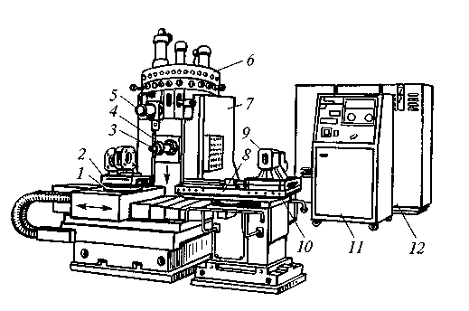
Figure 18 - Multi-purpose machine (machining center) mod. IR-500MF4:
1-table rotary; 2-device; 3-spindle; 4-spindle headstock; 5-autooperator; 6 tool magazine; 7-movable rack; 8-swivel platform; 9-table satellite; 10-guides; 11-CNC; 12-cabinet with electrical equipment.
The processing of workpieces on MS, in comparison with their processing on milling, drilling and other CNC machines, has a number of features. Installation and fastening of the workpiece must ensure its processing from all sides in one installation (free access of tools to the surfaces to be machined), since only in this case multilateral processing is possible without reinstallation.
Machining on MS does not, as a rule, require special equipment, since the workpiece is fastened with the help of stops and tacks. The MS is equipped with a tool magazine, placed on the spindle head, next to the machine or elsewhere. For milling planes, cutters of small diameter are used and processing is carried out with lines. Cantilever tools used for processing shallow holes have increased rigidity and, therefore, provide the specified machining accuracy. Holes lying on the same axis, but located in parallel workpiece machines, are bored from both sides, turning the table with the workpiece for this. If blanks of body parts have groups of identical surfaces and holes, then in order to simplify the compilation of the technological process and the program for their manufacture, as well as to increase processing productivity (as a result of reducing auxiliary time), constant cycles of the most frequently repeated movements (when drilling, milling ). In this case, only the processing cycle of the first hole (surface) is programmed, and for the rest, only the coordinates (X and Y) of their location are specified.
As an example, Figure 19 shows some canned cycles included in the software and used when processing on machines of the IR320PMF4 model.
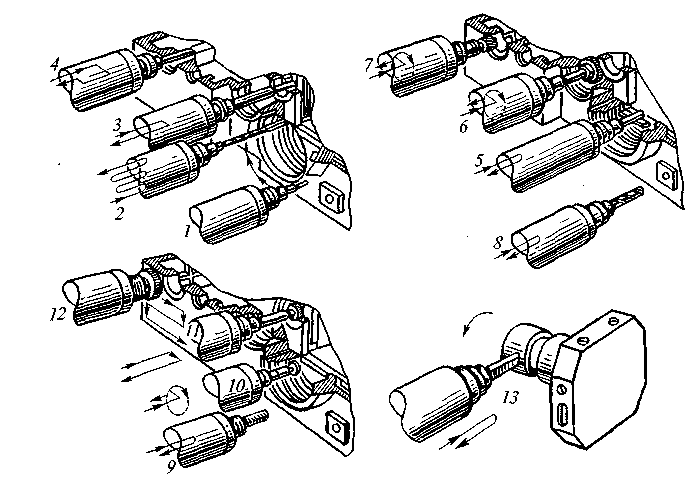
Figure 19 - Canned processing cycles on a multi-purpose machine model IR320PMF4:
1-outer contour milling (with circular interpolation), 2-deep drilling with drill exit for chip removal; 3-boring of stepped holes; 4-back counterbore using spindle orientation; 5-boring a hole Ø 125 mm using a special mandrel; 6-milling along the contour of the inner ends; 7-counterbore by contour milling (with circular interpolation); 8-hole drilling Ø 30 mm; 9-threading (up to M16); 10-milling of internal grooves with a disk cutter (with circular interpolation); 11 counterbore holes; 12-milling the ends with a cutter; 13-treatment of surfaces such as bodies of revolution.
The device for automatic change of device - satellite (PS) on the machine model IR500MF4 is shown in Figure 20. PS 11 is installed on platform 7 (capacity two PS), on which hydraulic cylinders 10 and 13 are mounted. The rods of the hydraulic cylinders have T-shaped grips 14 and 6. When installed on the platform (moving along arrow B), the PS cutout 12 engages with the capture 14 of the rod. On the platform, the PS is based on rollers 9 and is centered (on the sides) by rollers 8 (the initial position of the PS is in the waiting position). The movement of the rod of the hydraulic cylinder 10 causes the satellite to roll (on the rollers).
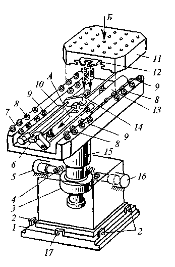
Figure 20 - Device for automatic change of device-satellite:
1-base plate; 2-adjusting bolts; 3- gear wheel; 4-rail; 5, 13,16-hydraulic cylinders; 6, 14-capture of the rod; 7-platform; 8.9-rollers; 10, - hydraulic cylinder rod; 11-device satellite; 12-shaped cutout; 15-stand.
When the rod of the hydraulic cylinder 13 moves, the gripper 6 moves (along the guide rod) and rolls the PS along the rollers 9 and 8 (in the direction of arrow A) onto the turntable of the machine, where the satellite is automatically lowered onto the clamps. As a result of capture 6 disengages from the PS and the machine table (with a satellite attached to it) moves at high speed into the processing area.
The workpiece is fixed on the satellite during the processing of the previous workpiece (when the PS is in the waiting position) or in advance, outside the machine.
After the workpiece is processed, the machine table automatically (at high speed) moves to the right to the device for changing the satellite and stops in a position in which the figured groove of the PS is under grip 6. The turntable hydraulic cylinder will unlock the satellite, after which the PS enters engagement with gripper 6, and oil enters the rod end of hydraulic cylinder 13, the rod moves to the extreme right position and the satellite moves from the workpiece to platform 7, where the PS with the new workpiece is already located. To swap the satellite, the platform is rotated by 180° (on machine 15) by a gear wheel 3 coupled with a rail 4 driven by hydraulic cylinders 5 and 16.
Platform 7 is accurately aligned with the turntable of the machine using adjusting screws 2 and 7 screwed into the protrusions of the base plate 1, which is fixedly fixed on the foundation.
Control questions:
What is the difference between multi-purpose CNC machines from turning, milling, drilling and other CNC machines?
Tell us about the main components of a multi-purpose machine for processing workpieces of body parts.
CNC Machining
The basis of modern numerical control systems for metalworking equipment is advanced technological solutions in the field of hardware and software, new information technologies and technological components.
CNC systems with an open class architecture opened a new page in the history of machine numerical control devices. The use of standard or industrial personal computers as the base platform for the CNC provides wide opportunities for unification and, at the same time, access to huge memory resources, computing power, standardized communication tools (interfaces), all kinds of system, tool and user software, and much more provided by rapidly growing information technology industry.
Let's take a look at some of the proposed Russian market the most popular foreign systems and pay tribute to individual domestic developments. We do not pretend to be a complete review, our goal is to talk about the fundamental decisions.
Foreign systems
Siemens
For the past thirty years, Siemens has been one of the trendsetters in the CNC machine tool market. What does Siemens represent today? In the field of CNC, the company has expanded its range and now offers CNC systems not only for complex machines working on large series.
For simple machines, the company offers a CNC family (2 axes + spindle for lathes and 3 axes + spindle for milling machines). As drives, both modern three-pole stepper motors (with CNC Sinumerik 802S) and AC servo drives with an analog interface (with CNC Sinumerik 802C) can be used.
Stepper drives can significantly reduce the overall cost of the machine, and therefore are especially popular in the simplest, smallest machines used by small firms that supply components to larger firms or produce small series of parts for their own needs, while maintaining a constant level of quality and getting rid of problems of finding highly qualified specialists.
The use of servo drives with an analog interface (+/-10 V) allows you to increase the accuracy of surface treatment on the same machines or, which is very relevant today in the CIS market, use the Sinumerik 802C CNC for machine modernization tasks, and it becomes possible to leave old drives, which significantly reduces the cost of modernization. At the same time, the productivity of the machine is increased due to the fact that new system The CNC is more reliable in operation, and the new CNC functions allow you to reduce the processing time of the part.
Modification Sinumerik 802C allows you to use it as a simple digital display for digital machines. Moreover, its cost is comparable or even lower than the classic display systems that exist on the market.
Closely adjacent to these CNCs is the Sinumerik 802D system, which adds another axis (for example, to control the table) and works with the Simodrive 611U universal servo drive.
For more complex machine tools, Siemens offers the already trusted Sinumerik 810D with CCU1 and CCU2 and Sinumerik 840D with NCU 571 and NCU 572 processors. turning or milling, but also technologies such as grinding, laser cutting, punching and robot control. These systems work in conjunction with the Simodrive 611D digital drive to achieve precision and dynamics unattainable with a traditional analog drive.
For complex forming technologies, model preparation and high-speed machining of carbide parts, the Sinumerik Power line is offered, currently represented by the Sinumerik 810D CNC with CCU3 and Sinumerik 840D with NCU 573. A separate line is the Sinumerik 840Di CNC system. This is a so-called PCNC control system based on a standard industrial PC. At the same time, the user interface and the CNC core are implemented in software, and the PLC controller and interfaces for connecting peripherals and drives are on a single slot-board. The same universal drive Simodrive 611U as for Sinumerik 802D is used as a drive.
The emergence of new functions in the CNC allows today to significantly reduce the changeover time of the machine, which in universal machine can take up to 90% of the total work time. Other features avoid costly tool breakage and costly part damage. Tool wear can also be reduced with CNC software functions. Improving the quality of surface treatment using CNC systems from Siemens makes it possible to eliminate the need for finishing parts and thereby not only reduce production time (i.e. increase productivity), but also reduce the fleet of expensive machines.
GE Fanuc Automation
GE Fanuc Automation CNCs are in demand for their high operational reliability and performance. The company produces CNCs of open and traditional types, which increase the productivity of machine tools by providing access to information and software tools in the machine itself. GE Fanuc CNC systems are designed for such a wide range of operations as: grinding, drilling, cutting, milling, punching, turning, woodworking and more.
CNC traditional type.
The GE Fanuc CNC control unit in all models of the new CNC series is only 60 mm thick. Built into the unit, a miniature CNC printed circuit board allows full use of the capabilities of the latest LSI and surface mount technologies. The board is mounted behind the liquid crystal display. The company has also developed a high-speed serial servo bus and a compact I/O distribution module that allows one CNC control unit and multiple servo amplifiers to be connected to a single fiber optic cable. Various input-output modules can be mounted on the operating panel and on the control panel of the machine, which can significantly reduce the amount of electrical automation of the machine and its size. The production system can be enhanced with Factolink, which can use the CNC as the end device of the operating system.
CNC open type.
The whole range of CNC open type GE FANUC is represented by the 160i, 180i, 210i and 160is, 180is, 210is series, developed from the 16i, 18i and 21i series. The "is" series CNCs are the smallest and thinnest of the open type CNCs. The printed circuit board compatible with the MS Windows CE Pocket PC function is mounted behind the LCD color display. The panel is designed using the latest LSI and surface mount technologies. The 160i, 180i, 210i series combine the reliability of a stand-alone CNC with the power of a GE Fanuc smart terminal. Open type CNCs provide highly efficient implementation of GE Fanuc CNC control functions simultaneously with personal computer functions and the possibility of their further expansion. Due to their high reliability, they can be used with confidence in industries of any level. The CNC device and the machine can be controlled using a graphical user interface of a personal computer. In addition, network capabilities can be used to exchange information, and database software can be used to manage service programs. Using the most advanced features of a personal computer, it is possible to transform the simplest machine into a machine with intelligent capabilities. The application software is supported by Microsoft Windows 95/98, Windows NT4.0 and Windows 2000 for "i" series open type CNC, Microsoft Windows CE for "is" series open type CNC. Mechanics can develop application software for the machine, just like for a conventional computer. The GE Fanuc software (CNC library) is used to input/output internal CNC information. Such software may support the standard set of Microsoft programming languages (Visual Basic or Visual C++TM) as well as exchange via OLE/DDE. It is possible to easily install any application software.
In addition to the companies already mentioned, the Russian market has products from such foreign companies as Heidenhain, Bosch Rexroth, IPA, Indramat, Andron GmbH, M&R Numeric (all Germany), Italian Fidia, OSPI, Olivetti, Japanese Mitsubishi, Toshiba, Hitachi, American Allen- Bredley and others.
On the benefits of cooperation
Of the CNC systems manufactured in the former Soviet republics, one can note the products of MSHAK CJSC (Armenia) and the Ukrainian company West Labe.
The MSHAK-DELTA TAU CNC system with an open architecture of the PC-based class is built on the basis of standard or industrial personal computers. A powerful programmable multi-axis controller PMAC from Delta Tau Data System, Inc. is installed on the computer. (USA), which manages all subsystems of the machine in real time. This is just one board installed on the ISA (or PCI) bus, carrying the functions of controlling the movement of axes (up to 32) and controlling electrical automation (PLC up to 2048 I/O). The system is able to provide simultaneous control of 8 machines, the number of synchronous (interpolated) axes is 32.
The WL4T CNC system from West Labe is the base model of the second generation 2-axis contouring control system of the WL4 family and is designed for use in vertical lathes and lathes with basic automatic control functions. Number of simultaneously controlled coordinates 2 + 1 (faceplate). Interpolation methods - linear and circular.
Domestic solutions
Balt-System Company (St. Petersburg) offers two CNC systems of the latest generation NC-110 and NC-200.
The NC-110 system is characterized by a combination of versatility and reliability. The system is built on a modular basis and allows you to meet the growing requirements of consumers by installing additional modules. The NC-200 system is a small-sized, monoblock device in which the control unit, operator's console and machine console are combined into one whole.  These systems provide users with a wide range of technological options, including: parametric programming, programming in elements of vector geometry, programming of two virtual axes, scaling dimensions, shifting the zero of the part and rotating the machining plane, vector compensation of the radius at the tip of the cutter during turning, control of a motorized tool; the possibility of activating milling and boring cycles during turning and much more.
Devices CNC "Mikros" series 11, 12T, 12TV, manufactured by CJSC "Mikros" (a subsidiary of JSC TsNITI), are based on modern computer technology industrial type and have a convenient block layout. They are based on an industrial computer and a hard real-time operating system that guarantees fast control response. HDD large capacity provides virtually unlimited memory for process control programs.
The user is given full control over the functions and operations performed and the state of the machine and the CNC system.
The built-in editor makes it possible to enter and correct control programs. Programming is carried out using G-functions and three-letter codes.
The available graphic support mode allows you to visualize the actual movement of the tool and check the programmed elements of the tool path even before the start of processing.
In addition, CNC systems of the Mikros series have advanced functions for compensating machine mechanics errors: non-straightness and non-perpendicularity of the guides, non-parallelism of the Z-axis guides - the spindle rotation axis, the gap in the mechanical feed; as well as the function of compensating for the inconsistency of the radius of the cutting edge of the cutter.
Autonomous system self-tuning allows you to determine the optimal position control parameters for each axis.
The universal system FMS-3000 by Modmash-Soft (Nizhny Novgorod) is a high-performance numerical control system designed for installation on different types technological equipment: milling machines, copy machines, machining centers, lathes and other CNC equipment.
Adaptation to a specific type of machine is carried out with the help of an electroautomatic program and an extensive system of parameters FMS-3000.
The basis of the FMS-3000 is an industrial-grade personal computer manufactured according to the latest technologies. The open architecture of the FMS-3000, combined with powerful software, makes it easy to integrate computer components from leading manufacturers of computer equipment into its structure.
The system software is implemented on the basis of the hard real-time kernel using the RT-Kernel library, which guarantees high quality of timer tasks for controlling servo drives and electric automation cycles. open structure system allows you to include in the system software modules user.
Since 1992, the Izhevsk NPP IZHPREST has developed and mass-produced CNC Mayak-400 (1992) and Mayak-500 (1999). The latest development of the company is the CNC system Mayak-600. The Mayak-600 numerical control system is designed for completing new machines and upgrading old ones.
The system layout concept is a separate CNC unit and a separate operator console, connected by a serial interface. The CNC unit is built into the electrical cabinet of the machine, and the operator's console is installed in the machine console or electrical cabinet. Mayak-600 allows you to control eight coordinate axes and a spindle. The feed drives and the spindle are controlled by an analog signal (+/-10 V). Photoelectric and inductive feedback sensors can be connected to the measuring circuits. There is a CNC version for controlling stepper motors.
Some functions of the system: the ability to run the program from any frame with automatic determination of the initial conditions (starting point and G-functions), diagnostics of blocks when turned on and during operation, a multi-level system for accessing machine data, editing control programs, parameters, correctors from the operator's console , the ability to work out control programs with a volume of 30 MB or more, helical interpolation, linear interpolation along all axes simultaneously.
Types of displacement transducers - inductive and photoelectric (circular and linear). The CNC includes an integrated programmable controller.
WinPCNC system. The WinPCNC system (NCSYSTEMS.RU, Moscow) is a single-computer CNC system built on a powerful platform of a personal computer with an operating Windows system NT and VentureCom's RTX 4.1 real-time extension. It belongs to the PCNC class. The system uses a single processor to handle all of its functions, including the electrical functions. The hardware part is represented by standard personal computer equipment and additional interface modules for communication with feed and main movement servo drives, electric automation drives, operator panel. The CNC system consists of two independent blocks - the system block and the operator panel. System unit housed in an industrial computer case. The operator panel block is built into its housing and is structurally designed in a way that is convenient for the consumer. The system unit is a basic set of boards on the PCI bus. There is also the possibility of installing additional boards: for example, to increase the number of controlled coordinates, to increase the total number of parallel inputs / outputs of electric automation, to install network interface boards of the Fieldbus type to control drives and electric automation.
The operator interface is open to include any end user applications developed in the Windows environment. At the same time, a wide open set of API interface functions is provided to end users. Operator interface (his appearance, set of modes, pages and menus) can be significantly redesigned in the shortest possible time using a special tool system State_Machine_Builder. The CNC system can be set to any version of the part program language in ISO-7bit code (DIN 66025). The customized version is supported by the control program debugger and the flexible control program interpreter (ISO processor). The interpreter can be set to any (reasonable) number of buffered frames. The editor-debugger has a system for graphical simulation of the control program at the input of the system and at the output of the interpreter, i.e., taking into account the equidistant. The system interpolator has a flexible proprietary architecture and a fixed IPD (Interpolator Data) input interface; it is open to include any special interpolation algorithms. Any combination of available algorithms can be used in the control process. The flexible electroautomatic system is built on the basis of the SoftPLC concept, i.e., on the basis of the software implementation of the controller as part of the application component of the CNC system. The interaction of all modules of the CNC system is carried out through a multifunctional software bus, which serves as the global server of the system. Such an organization allows the scaling of the system.
CNC systems 4CKFF (CJSC 4C) are mass-produced representatives of the 4CK series, developed and put into production in St. Petersburg together with Olivetti. MC/TC devices control machine tools, machining centers, flexible modules, and GP devices control special types of machine tools, robots and automatic lines. The control of five (MSGGS) and an unlimited (GP) number of technological processes in real time allows you to simultaneously execute several control programs in the CNC, for example, from one device to control the processing of parts on several machines at the same time. 4CKFF is 10 times faster than previous 4CKFF, allowing you to make the most of the software's powerful features.
A total of 8 functionally different hardware modules reduces the technological complexity of production, simplifies service maintenance and ensures software and hardware compatibility of modern and previously produced 4SK. In 2000, an almost complete transition was made to the use of foreign-made element base in 4CKFF, which determines the quality and reliability. Production of CNC 4CKFF, including related productions: printed circuit boards, metal structures, keyboards - concentrated in St. Petersburg.
The new CNC system with a high degree of electronic integration "Mini 4CKFF" based on a small-sized control unit (294x356x262 mm) for 5 platforms, modular and software compatible with previous 4CK models, provides control of 6 coordinate axes (+2 spindles) and has 112/64 discrete inputs/outputs.
The CNC system Arta NVP "Arta-Test" (Fryazino, Moscow region) is designed to control electroerosive machines with up to 5 controlled coordinates and is a further development of the CNC "Arta" DAKSh3.035.002 produced in recent years.
Both stand-alone CNCs and those with a built-in BERM-2M generator are produced. The system is made on the basis of a modern Intel architecture computer with a Pentium processor. It is completed with its own series-produced units: drives stepper motors, ADC, electronic disk with built-in ROM of working software and static memory for storing parameters and processing coordinates when the power is turned off, power supply.
The operator's interface with the CNC is provided by a 15-inch color graphic monitor, a retractable keyboard of the operator's console, and a control panel (in the case of the CNC version with a built-in BERM-2M generator, it is supplemented with elements for regulating and indicating the parameters of technological impulses).
CNCs are manufactured according to the “plug-in-plug” principle both for new equipment and for the modernization of previously manufactured EDM and laser equipment.
LLC "Rus Avtomatika" (St. Petersburg) offers universal, multifunctional CNC systems of the UNIC family, based on a modern industrial PC computer controlled by operating system Windows-98 and higher, which makes them as adaptable as possible to the specific needs of the consumer. CNC system UNIC-23 - good decision for machining centers, multifunctional milling and turning equipment. The UNIC-22F,T CNC system is designed to control simple milling and turning machines, it is used in metal and woodworking, as well as in cutting equipment. The UNIC-21 CNC system is a modular system that allows you to control complex technological equipment, technological processes monitored by multiple sensors. It is most effectively used in the light and food industries.
The CNC system KRT4-00 NPO KRISTA (Rybinsk) is built on the basis of a computer in industrial design. The system includes: graphic display, alphanumeric and functional keyboard, processor unit, communication boards with technological equipment, power supply. The CNC can be used both for upgrading existing equipment and for use in newly developed systems. The number of controlled coordinates is up to 6, the control of feed drives is determined by the type of drive, the type of position sensors is incremental photoelectric.
The system supports the following types of interpolation: linear - along all six coordinates simultaneously, circular - along any two linear coordinates simultaneously, linear-circular - along any three coordinates simultaneously, automatic contour correction by the radius value and tool length.
The input of control programs is possible by typing from the alphanumeric keyboard of the CNC (a full-featured text editor), by loading previously entered programs from the internal non-volatile memory of the control system or by loading from an external data carrier (3.5-inch floppy disk; portable non-volatile memory modules; computer network, twisted pair 10 Mbps).
Some specifications individual CNC systems are shown in the table.
Still, Siemens
As you can see, the Russian market for CNC systems is very representative and full of offers. Moreover, almost every manufacturer offers from one or two to a dozen or more models and modifications.
There are a lot of offers, but what is bought, what CNC systems are preferred? Various sources information converge approximately on such numbers: the share of foreign CNC systems sold in Russia is from 60 to 70%, respectively, the share of domestic products is 30-40%. Sources of information also agree that the undisputed sales leader is Siemens (up to 90% of sales among foreign CNC systems).
The author of this material also did not escape the temptation and, in turn, tried to evaluate what CNC systems the new metalworking equipment offered on the Russian market is equipped with. Fifty manufacturers were taken, of which 34 were foreign (American, German, Swiss, Japanese) and 16 Russian, such as St. Petersburg's Sverdlov, machine-tool factories from Sterlitamak and Ivanov, Moscow's Krasny Proletarian, and others. So, out of these fifty: 28 companies offer equipment equipped with Siemens CNC systems, 15 - GE Fanuc, 8 - Heidenhain, 9 - others foreign firms(including own developments) and 4 - domestic firms (the sum is not equal to 50, since a number of manufacturers equip machine tools different systems).
In addition, out of ten companies (both Russian and foreign) offering to modernize machine tools, almost all offer Siemens products as an alternative to the CNC systems installed on this equipment.
Thus, it can be stated (probably with regret, but it is true) that the Russian market is currently dominated by Siemens products. This company has always been a leader in the production of CNC systems, which is based on vast experience and almost unlimited engineering and technological capabilities. There is only one "weak point" - according to Russian concepts, it is expensive.
Recently, the presence on the Russian market of American and Chinese manufacturers of CNC systems has become noticeable. But unlike Siemens, they do not have a wide network of representative offices capable of providing maintenance, repair and consulting services.
While noting with regret the state’s lack of interest in the development of this undeniably strategic industry, it should be noted that the emergence of new enterprises specializing in the production of such products, the emergence of new modern models of it, nonetheless make it possible to look to the future with cautious optimism.
CNC systems of the first generation had an element base based on discrete semiconductor elements (transistors). The input of the program in these systems was carried out on a magnetic tape in a unitary code or in a phase form. Models of CNC devices of the first generation are PRS1-58, PRS-ZK, K-4MI. At the same time, in CNC devices of the first generation K2P-67, KZP-68, UMS-2, the program was entered already on a five-track punched tape (code BCC-5).
Second generation CNC systems
CNC systems of the second generation had an element base of small (series 155) and medium (series 176) degrees of integration, with the help of which the circuit implementation of control algorithms was carried out. The models of CNC devices of the second generation include H22, NZZ, H55, P-33, "Size 2". In CNC devices of the second generation H22, N3Z, the program was entered on an eight-track punched tape (code ISO 7).
Third generation CNC systems
CNC systems of the third generation were created on the basis of microcomputers ("Electronics-60", "Electronics NTs-03", etc.), BIS (series 589, etc.). These CNC systems had advanced technological capabilities, software implementation of control algorithms was carried out. The models of CNC devices of the third generation include 15MP, "Size 4M", 2S42, 2S85, 2U32, 2MCHZ, "Electronics NTs-31". In CNC devices of the third generation, the program was entered both on punched tape and using the keyboard. CNC systems are beginning to be equipped with display-dialog systems for setting NC with a graphical display of the part on the screen. There are operational CNC systems on which the programming of simple parts can be carried out directly on the machine using typical cycles.
Fourth generation CNC systems
For CNC systems of the fourth generation, block multiprocessor execution is typical. As an element base, special LSI and microcomputers are used. Programming of technological functions and dialogue modes is carried out in high-level languages. The fourth generation CNC devices include Elektronika MS2101, ZS100, ZS200. In CNC devices of the fourth generation, the program was entered by an electronic cassette or a cassette on digital magnetic domains.
Fifth generation CNC systems
CNC systems of the fifth generation are created on the basis of industrial personal computers. These CNC systems implement all the modern achievements inherent in personal computers, including programming languages; software and mathematical support; systems of input, storage and exchange of information; possibility of structural change; the ability to perform self-tuning and adaptation functions, etc.
CNC machines are divided into the following technological groups:
- lathe group;
- machines of drilling-milling-boring group;
- grinding group machines;
- gear group machines;
- machines of the electrophysical group;
- multi-purpose machines, OTs:
In relation to the instrument
- with manual tool change;
- with automatic tool change in the turret;
- with automatic tool change in the magazine.
Machines can be equipped with different CNC systems. Depending on the configuration of the control system, the designations of metal-cutting machines can be as follows:
- F1 - machines with digital indication, including those with a preliminary set of coordinates;
- F2 - machines with positional rectangular coordinate control systems;
- F3 - machines with contour rectilinear and curvilinear coordinate control systems;
- F4 - machines with universal systems coordinate control for position-contour processing.
To characterize CNC machines, the following indicators are used:
- Machine accuracy class
- H - normal precision machine
- P - increased
- B - high
- A - especially high
- C - ultra-high precision (master machine)
- for cartridge machines - the largest diameter of the product to be installed above the bed, the largest diameter of the workpiece above the bed;
- for center and chuck machines - the largest diameter of the workpiece above the caliper;
- for bar-turning machines - the largest diameter of the processed bar;
- for boring and milling machines - overall dimensions (length, width) of the working surface of the table, diameter of the working surface of the round rotary table;
- for drilling machines - the largest nominal diameter drilling, the diameter of the retractable spindle, etc.;
On the basis of CNC machine tools, the following machine modules and machine complexes designed for automated processing of parts have been created (common international designations of systems are given in brackets):
GPM (FMM) - flexible production module- a unit of technological equipment with an automatic loading / unloading system for parts, a local storage, a conveyor for parts and tools;
GAL - flexible automatic line- a system that includes several GPMs, with general management from a computer, a transport system and a warehouse for blanks. The computer performs the functions of storing and transferring control programs to the CNC machine tool, and also carries out current scheduling and operational planning;
GPS (FMS) - flexible manufacturing system- a complex of technological equipment and a computer-based control system, which has the property of automated changeover;
GAD (FMF) - flexible automated workshop- a system that includes several HALs and GPMs with a common transport system, a warehouse, a multi-level (hierarchical) computer control system;
A3 - automatic winding- a system consisting of a GAD, including an automatic assembly shop and packaging of finished products. The central computer controls all departments of the plant and long-term planning.
Designs of CNC devices, high-level control systems are constantly being developed and improved. A new element base appears, technological capabilities expand, the degree of automation, productivity and processing accuracy increase. Therefore, the manual provides information about the prospects for the development of control systems and new requirements for the profession of a CNC machine operator.
CNC systems. Terms and concepts
Metalworking equipment with program control any type of machine tools for metal processing by cutting, for example, turning, milling, drilling, grinding, boring, multi-purpose, electroerosive, etc., as well as other types of equipment for metal processing (sheet bending machines, punch presses, etc.) a given program for automatic processing of workpieces.
Control program (CP)- a set of commands in the programming language, corresponding to the algorithm of the machine for processing a particular workpiece.
Numerical control of machine tools- control of the processing of the workpiece on the machine according to the UE, in which the processing data is specified in a digital code.
Program carrier- a carrier of geometric and technological data on which the UE is recorded. As a data carrier, paper or plastic punched tape, magnetic tape, magnetic disks, storage devices are used. different types and types.
Geometric Information- information describing the shape, dimensions of the elements of the part and tool, their relative position on the machine table.
Technological information- information describing the technological characteristics of the part and the conditions for its processing.
UE frame- a component of the program, entered and worked out as a whole and containing at least one command.
Frame-by-frame work- the operation of the CNC device, in which the processing of each frame of the UE occurs after the impact of the operator.
CNC operation with manual data entry- the operation of the CNC device, in which a set of data, limited by the frame format, is performed manually by the operator on the machine control panel.
CNC operation with manual control- the operation of the CNC device, in which the operator controls the machine from the console without the use of numerical data.
Mirror Processing- the operation of the CNC device, in which the working bodies move along a trajectory, which is a mirror image of the trajectory recorded in the UE.
Entering UE- data input into the memory of the CNC device from the program carrier from the computer of the highest rank or from the operator's console.
Group CNC machines- numerical control of a group of machine tools from a computer that has a common memory for storing programs distributed by requests from machines.
Zero fine machine- a point on the machine node, taken as the origin of the machine coordinate system.
Coordinate- a value that determines the position of a point in space with respect to a given base or origin.
Machine origin- a point on the machine node, defined relative to the machine zero point and used to start work on the NC.
Machine fixed point- a point defined relative to the zero point of the machine and used to determine the position of the working body.
Processing start point- a point that determines the start of processing a particular workpiece.
floating zero- the possibility of moving by means of the CNC device the origin of the movement of the working body to any position relative to the zero point.
Displacement task resolution- the minimum movement of the working body (linear or by the angle of rotation), which can be set in the UE.
Discreteness of movement processing- minimum movement or minimum angle of rotation of the working body, controlled in the control process.
Maximum programmable travel- the largest movement of the working body, which can be set in one frame of the UE.
contour speed- the resulting feed rate of the working body, the direction of which coincides with the direction of the tangent at each point of the specified processing contour.
Tool position offset- change from the control panel of the programmed coordinates of the working body of the machine.
Feedrate override- change from the operator's console of the programmed value of the feed rate.
Main motion speed correction- change from the operator's console of the programmed speed of the main drive.
CNC failure- an event consisting in a violation of the operability of the CNC device.
CNC failure- an event consisting in a short-term self-correcting violation of the operability of the CNC device.
Indicated CNC fault- a failure that is fixed on the console at the time of its occurrence, leading to a machine stop, i.e. to the termination of the processing of the part, information about which is displayed on the operator's console.
Unindicated CNC fault- a failure that is not detected on the console at the time of its occurrence.
CNC machine system- a complex of units and assemblies interacting with each other.
A typical replacement element for a CNC device (TEZ CNC)- a typical minimum component of the CNC device, which, in case of loss of performance, can be replaced by a similar one. Each CNC device issues a control action on the executive bodies in accordance with the UE and information about the position of the controlled object.
Classification of CNC systems
Domestic classification of CNC systems
The classification of CNC systems used in domestic mechanical engineering is carried out according to the type of working movements. Distinguish between positional and contour CNC devices.
CNC Positioning Devices- devices in which the working bodies can move to given points, and the trajectory of movement from point to point is set only by rectilinear movement. CNC positioning devices constitute a group of devices that have one common feature - positioning, i.e. ensuring the accuracy of stopping the moving working bodies at a point with given coordinates. The travel speed in positioning devices is not programmed and is determined only by the dynamics of the machine drives. CNC positioning devices are equipped with drilling, jig boring, turning, milling, grinding and other machines operating on a rectangular cycle.
Contour rectangular (collinear) CNC devices- devices that provide movement along one coordinate. Since most machines use a rectangular coordinate system, such devices are called rectangular. In these devices, as well as in positional ones, the final coordinates of the movement are programmed, however, in the UE, the speed of movement of the working body is set in accordance with the specified cutting mode, and the movement is performed alternately along each of the coordinate axes. Rectangular CNC devices are used in machines of milling, turning and grinding groups.
Contour (continuous) CNC devices- devices that ensure the movement of working bodies from a given point in space along a trajectory, the shape and final coordinates of which are specified in the UE. CNC contouring devices are equipped with machines of the milling and turning groups, which carry out the shaping of parts of complex shape.
Devices for adaptive (self-adapting) CNC control- devices that automatically adapt the processing process to changing processing conditions according to certain criteria (cutting speed, feed, cutting force). Self-adapting CNC devices have a control and regulation system that allows for overload protection of the main movement motors and feed drives, which ensures high quality processing and protects the machine system from breakdowns. Adaptive CNC devices equip milling, boring and multi-purpose machines.
Operational Control System (OCS)- CNC device based on a microcomputer with NC preparation at the machine tool in the mode of the operator's dialogue with the CNC device. The operator, using the keyboard of the CNC control panel, enters data from the part drawing into the control program. CNC operating devices are equipped with turning and milling machines.
Another feature by which CNC devices can be classified is the number of information flows circulating in the machine-CNC system.
Open loop system- a CNC device in which there is only one stream of information. In such systems, there are no measuring devices (feedback sensors) that control the movement of working bodies. The accuracy of reproduction of the movement of the working bodies with such a system is low and is determined by the accuracy of processing commands by the feed drive engine and the accuracy of the kinematic chain that transmits the movement to the working body.
Closed Loop System- CNC device, in which there are two information streams: one is entered into the control device through the input device from the program carrier, and the other - into the CNC device from feedback sensors that determine the actual position of the working bodies. If there is a mismatch between these flows, the control device acts on the feed drives, the latter move the working bodies in the right direction, changing the mismatch to a value close to zero.
International classification of CNC systems
In accordance with international classification All CNC according to the level of technical capabilities are divided into the following classes: There are CNC devices with a constant (NC class) and variable (CNC class) structure.
CNC class NC (Numerical Control) is based on the principle of a computing device, where all operations that make up the algorithm of work are performed in parallel using separate circuits or devices that implement a particular function (aggregate-block construction). These devices are also called rigid structure CNC devices. The basic models of such devices (H22 and N3Z) contain microelectronics and when using them, operator intervention in the processing process is very limited.
NC-class CNC systems perform frame-by-frame reading of punched tape during the processing cycle of each workpiece
NC class systems are the most common. They work in the following mode. After turning on the machine, the CNC reads the first and second blocks of the program. As soon as they are finished reading, the machine starts executing the commands of the first frame. At this time, the information of the second block of the program is in the memory of the CNC system. After executing the first frame, the machine starts working on the second frame, which is output from the memory device. In the process of working out the second frame by the machine, the system reads the third frame of the program, which is entered into the storage device freed from the information of the second frame.
The main disadvantage of the considered mode of operation is that in order to process each next workpiece from the batch, the CNC system has to read all the frames of the punched tape again. At the same time, in the process of reading punched tape, failures often occur due to insufficient reliable operation CNC readers. As a result, individual parts from a batch may be defective. The increased probability of failures in NC-class systems is also explained by the very large number of punched tape frames, since for the operation of such systems, each elementary action of the machine must be recorded in the program. In addition, with this mode of operation, punched tape quickly wears out and becomes dirty, which further increases the likelihood of reading failures. Finally, if the block contains actions that the machine performs very quickly, then the CNC may not have time to read the next block during this time, which also leads to failures.
CNC class device (Computer Numerical Control(with a variable structure) corresponds to the structure of the control computer, which includes a computing device (processor), memory blocks and information input-output blocks. At the same time, the scope of functions, the nature of the operations performed and their sequence are determined by the operation programs that are entered into the memory block.
CNC class systems have great potential due to the presence of minicomputers based on microprocessors. The program can be entered into the storage device of the system not only completely from the prepared punched tape, but also by individual frames manually from the CNC control panel. In program blocks, both commands for individual movements of the working bodies, and commands that define entire groups of movements, called canned cycles, which are stored in the memory of the control system, can be recorded. This leads to a sharp decrease in the number of program frames and a corresponding increase in the reliability of the machine. CNC class systems make it quite easy to carry out editing in the dialogue mode when debugging programs with manual input of information and displaying it on the display, as well as receiving a corrected and worked out program on a punched tape.
A number of systems of the CNC class (or close to it) make possible job one program at different scales, in the "matrix - punch" mode, in the mirror image mode, etc. The systems allow the introduction of various types of corrections during operation.
With relatively low cost, small overall dimensions and high reliability, CNC systems on microprocessors make it possible to introduce new properties into the control system that could not be implemented before. So, for example, the CNC device "Electronics NTs-31" has software that allows you to take into account and automatically correct the constant errors of the machine and thereby influence the set of factors that determine the accuracy of processing. The simplest form of these functions of the system is the compensation of the backlash or the dead zone of the drives in the direction of movement along the coordinates. The reliability and performance of machine tools with CNC devices on microprocessors increases the use of monitoring and diagnostic systems. The functions of these systems can be divided into monitoring the status of devices external to the CNC, checking internal units and monitoring the CNC itself. So, for example, the same device "Electronics NTs-31" for lathes has special test programs to check the performance of all structural parts of the system. These test programs are worked out every time the device is turned on, and if all parts are in good condition, a signal is generated that the system is ready for operation. During the operation of the machine and the CNC, test programs are processed in parts in the so-called background mode, without interfering with the development of the main control program. In the event of a malfunction, a code appears on the light indication board, with the help of which, according to the table, the location and cause of the malfunction are determined. In addition, the system detects errors associated with improper operation of the device, exceeding the thermal conditions, gives the voltage for the power supply and other parameters.
Devices of the CNC class expand the functionality of program control: there are functions that could not be implemented before: storage of NC and its editing at the workplace, expansion of the indication on the display, dialog communication with the operator, wide possibilities for correcting, including machine errors, fault diagnosis system, changeable programmatically functions of the control system during its operation, the implementation of the functions of electric automation, etc.
In addition, there are CNC systems of other classes:
SNC (Stored Numerical Control)- CNC systems with a single reading of the entire punched tape before processing a batch of identical blanks;
CNCs of the SNC class are free from the disadvantages of the NC class systems, they sequentially, frame by frame, read the entire program and place the information in their large-capacity memory device (16 kilobytes or more). The punched tape is read only once, before processing the entire batch of identical parts, and therefore wears out little. The processing of all blanks is controlled by signals from the storage device, which dramatically reduces the likelihood of failures, and hence the rejection of parts. SNC systems allow one-time input of control programs with a punched tape length from 40 to 310 m.
DNC (Direct Numerical Control)- systems of direct numerical control groups of machines from one computer;
The creation and application of DNC class systems is associated with the general trend in the development of modern complex-automated production. In such industries, the operation of sections consisting of CNC machines, transport and storage, loading facilities is controlled from a central computer. However, the presence of a central computer does not mean that the need for CNC devices for machine tools is completely eliminated. In one of the most common options for building DNC systems, each type of equipment in the area retains its CNC systems of the NC, SNC, CNC classes. Normal for such a section is the mode of operation, in which control commands to the CNC of all types of equipment are sent via wires directly from the computer, bypassing the reading devices. This leads to an increase in the reliability of each piece of equipment and the entire site as a whole. At the same time, the process of preparing the UE with the help of a computer is automated. At the same time, under the conditions of a temporary failure of a computer, such a section remains operational, since each type of equipment can work from a punched tape prepared in advance in case of an emergency.
HNC (Handled Numerical Control)- operational CNC systems with a manual set of programs on the control panel.
Preparation and debugging of control programs is a long and laborious process. In the manufacture of parts with simple configuration, it would be advisable to exclude this process. Such a possibility on modern machines, in principle, is available. It is implemented using the manual data entry mode. However, for most machines in this mode, it is possible to enter only one block of the program from the remote control with its subsequent processing on the machine. It's too unproductive. Therefore, the so-called operational systems of numerical control of the HNC class with manual input of programs from the CNC console have recently been developed. A program from a sufficiently large number of frames is easily typed and corrected using the keys or switches on the CNC control panel. After debugging, the program is fixed until the end of processing a batch of identical workpieces. HNC class systems provide both positional and contour control of machine tools.
Bibliography
- GOST R 50369-92. Electric drives. Terms and Definitions. - M.: Publishing house of standards, 1993. - 16 p.
- Zavgorodnev P. I. Work of an operator on machine tools with program control: textbook. allowance for tech. schools / P. I. Zavgorodnev. - M.: Higher. school, 1981. - 136 p.
- Software control of machine tools and industrial robots: textbook / [V.L. Kosovsky, Yu.G. Kozyrev, A.N. Kovshov et al.]. - M.: Higher. school, 1989. - 272 p.
- Sergievsky L. V. Manual for CNC machine tool adjuster / L. V. Sergievsky, V. V. Ruslanov. - M.: Mashinostroenie, 1991. - 176 p.
- Solomentsev Yu. N. Management of flexible production systems / Yu. N. Solomentsev, VL Sosonkin. - M.: Mashinostroenie, 1988. - 552 p.
- Sosonkin VL Microprocessor systems of numerical control of machine tools / V.L. Sosonkin. - M. : Mashinostroenie, 1985. - 288 p.
- Cherpakov B. I. Metal-cutting machines: A textbook for the beginning. prof. education / B. I. Cherpakov, T. A. Alperovich. - M.: Publishing Center "Academy", 2004. - 368 p.
- Numerical control of machine tools / [V.L. Sosonkin, O. P. Mikhaylev, Yu. A. Pavlov et al.]; ed. V. L. Sosonkina. - M.: Mashinostroenie, 1981. - 398 p.
- Chudakov A.L. Designing control systems for machine tools and machine complexes: Ch. 1.8 // Engineering: Encyclopedia. T. FV-7. Metal cutting machines and woodworking equipment. - M.: Mashinostroenie, 19
Bosinzon M.A. Modern systems CNC and their operation: a textbook for the beginning. prof. education / M. A. Bosinzon; ed. B. I. Cherpakova. - 2nd ed., erased. - M.: Publishing Center "Academy", 2008. - 192 p. ISBN 978-5-7695-5184-0
Basic principles of numerical control
The development of electronics and computer technology, the introduction of computers into production has led to the development and widespread use in machine tool building of numerical control systems (CNC) for metal-cutting machines, as well as other technological equipment.
Numerical control of metal-cutting machines is called control according to a program specified in an alphanumeric code and representing a sequence of commands written on certain language and providing the specified functioning of the working bodies of the machine.
The fundamental difference between CNC systems and the previously considered ACS lies in the method of calculating and setting the control program and its transmission to control the working bodies of the machine. Detail drawing information is presented in analog-digital form, that is, in the form of numbers, various verbal instructions, symbols and other symbols that have a limited number of meanings, each of which has quite specific and unambiguous information.
In conventional ACS, the control program is embodied in physical analogues - cams, copiers, stops, jig plates and other means that are program carriers. This method task control program has two major drawbacks.
First is caused by the fact that the information of the drawing of the part from digital (discrete) and unambiguous turns into analog (in the form of cam curves, copier). This leads to errors introduced in the manufacture of cams, copiers, the arrangement of travel stops on the rulers, as well as the wear of these program carriers during operation. Second the disadvantage is the need to manufacture these software carriers with subsequent labor-intensive adjustment on the machine. It leads to high costs means and time and makes in most cases the use of conventional ACS for the automation of serial and especially small-scale production inefficient.
When preparing control programs for CNC machines up to its transfer to the working bodies of the machine, we are dealing with information in a discrete form, obtained directly from the drawing of the part.
The trajectory of the movement of the cutting tool relative to the machined workpiece in CNC machines is represented as a series of its successive positions, each of which is determined by a number. In CNC machines, it is possible to obtain complex movements of the working bodies not with the help of kinematic relations, but by controlling the independent coordinate movements of these working bodies according to a program specified in numerical form. Qualitatively new in CNC machines is the possibility of increasing the number of simultaneously controlled coordinates, which made it possible to create fundamentally new layouts of machine tools with obtaining wide technological capabilities with automatic control.
The control program can be calculated with any given accuracy and for any required law of movement of the working bodies of the machine. The control of machine tools directly from the computer is gaining more and more widespread use.
Classification of CNC systems
CNC systems can be classified according to various criteria.
I. Based on the technological tasks of processing control All CNC systems are divided into three groups: positional, contour and combined.
Positional CNC systems provide control of movements of the working bodies of the machine in accordance with the commands that determine the positions specified by the control program. In this case, movements along different coordinate axes can be performed simultaneously (for a given constant speed) or sequentially. These systems are mainly equipped with drilling and boring machines for processing parts such as plates, flanges, covers, etc., in which drilling, countersinking, boring holes, threading, etc.
CNC contouring systems provide control of the movements of the working bodies of the machine along the trajectory and with the contour speed specified by the control program. The contour speed is the resulting feed rate of the working body of the machine, the direction of which coincides with the direction of the tangent at each point of the specified processing contour. Contour CNC systems, unlike positional ones, provide continuous control of tool or workpiece movements one by one or simultaneously along several coordinates, as a result of which very complex parts can be processed (with simultaneous control over more than two coordinates). CNC contouring systems are mainly equipped with turning and milling machines.
Combined CNC systems, combining the functions of positional and contour CNC systems, are the most complex, but also more versatile. In connection with the complication of CNC machines (especially multi-operational ones), the expansion of their technological capabilities and the increase in the degree of automation, the use of combined CNC systems is expanding significantly.
II. Based on feedback All CNC systems are divided into two groups: open and closed.
Closed CNC systems, in turn, can be:
1) with feedback on the position of the working bodies of the machine; 2) with feedback on the position of the working bodies and with compensation for machine errors; 3) self-adapting (adaptive).
open CNC systems are built on the basis of power or step motors (SM). In the latter case, the stepper motor is usually used in conjunction with a hydraulic booster.
III. Classification depending on the level of electronic technology.
Despite the relatively short period of use of CNC systems, they have already gone through several stages in their development, determined by the level of development of electronic technology.
CNC systems currently used in industry class NC built on the basis of a digital model. In this system, the program (on punched tape) is entered into interpolator 3, further revised
the program is entered into the control system 2 machine 1. These CNC systems are called systems with a rigid program. The possibilities of operator intervention in the process of program processing are very limited on these systems.
In systems class SNC the device for reading the control program is used only once - to enter the control program into

storage unit 4 (memory). As a result, the reliability of the machine is increased due to the failure of the photoreader.
Feature of control systems CNC class is their structure corresponding to the structure of the control computer. With the advent of CNC class systems, the functionality of program control has expanded,
including storage of the control program and its editing directly at the workplace, advanced display options, dialog communication with the operator, etc. Entering the control program can be done on punched tape or manually. The second type of systems is called systems class HNC. The control program here is entered by the operator using the keyboard and stored in the system memory.
As well as autonomous systems CNC in industry use direct numerical control systems for a group of different machine tools from a single computer, called systems DNC class.
 In this system, a medium or large computer (3) prepares programs for several CNC machines and transfers them to the CNC systems (2) of individual machines (1). Due to the very high speed of the computer, the system prepares programs for all machines of the group. The computer also performs additional functions for managing a semiautomatic device, for example, it controls automated transport and a warehouse. Machine tools are directly controlled by minicomputers with a small volume random access memory included in individual CNC systems.
Typical block diagram of a CNC system
The figure shows a general enlarged block diagram of the CNC system. It includes the following main elements: CNC device; feed drives of the working bodies of the machine and feedback sensors (DOS) installed for each controlled coordinate. The CNC device is designed to issue control actions by the working body of the machine in accordance with the control program entered on the punched tape. The control program is read sequentially within one frame with storage in the memory block, from where it is fed into the blocks of technological commands, interpolation and feed rates. The interpolation block is a specialized computing device (interpolator) that formulates a partial trajectory of the tool movement between two or more points specified in the control program. The output information from this block enters the feed drive control unit, usually presented as a sequence of pulses for each coordinate, the frequency of which determines the feed rate, and the number determines the amount of movement.
Information input and reading block is intended for input and reading from the punched tape of the control program. Reading is performed sequentially line by line within one frame with periodic pulling of punched tape in front of a photo reader containing a photo reading head 11 with photo converters, and an illuminator,
consisting of an incandescent lamp 3 and a lens 4. Eight photoconverters provide information reading, and two are used to form a sync pulse through the holes of the transport track. In other devices, another photoconverter is used, which is installed along the edge of the punched tape to control its breakage.
Pulling punched tape 9 is carried out by drive roller 7, to which it is pressed by roller 10, when the broach electromagnet (EMF) is turned on and armature 6 is pulled. Drive roller 7 rotates by electric motor 8. When pulling the punched tape for its tension and tight fit to the photoreading head 11, it is braked by a brake 1 and is pressed against the head 11 by the clamp 5, which is retracted by the lever 2 when loading the punched tape. After reading the information of one frame, the punched tape is stopped by turning on the EMT brake and turning off the EMF electromagnet. Synchronization of their work is carried out by a control trigger (TG).
There are modifications to the input device.
Memory block. Since the information from the punched tape is read sequentially, and is used all at once within one frame, when reading it, it is stored in the memory block. Here, it is also monitored and a signal is generated when an error is detected in the punched tape. Since the processing of information proceeds sequentially by frames, and the time for reading information from one frame is approximately 0.1 - 0.2 s, a gap in the transmission of information is obtained, which is unacceptable. Therefore, two blocks of memory are used. While the information of one frame from the first memory block is being processed, the second frame is read from the punched tape and stored in the second block. The time for introducing information from the memory block into the interpolation block is negligible. In many CNC systems, the memory block can receive information bypassing the input block and reading directly from the computer.
interpolation block. This is a specialized computing device that forms a partial tool path between two or more points specified in the control program. This is the most important block in CNC contouring systems. The basis of the block is the interpolator, which, according to the numerical parameters of the contour section specified by the control program, restores the function f (x, y). In the intervals of X and Y coordinate values, the interpolator calculates the coordinate values of the intermediate points of this function.
At the outputs of the interpolator, control pulses strictly synchronized in time are generated to move the working body of the machine along the corresponding coordinate axes.
Linear and linear-circular interpolators are used. In accordance with this, the former perform linear interpolation, and the latter linear and circular.
The linear interpolator provides, for example, the movement of the working body with a cutter with a diameter between two reference points in a straight line with a deviation from the given contour by the value .
In this case, the initial information for the interpolator is the magnitude of increments in coordinates and and the processing time of moving along a straight line, i.e. , where S is the set tool feed rate.
The operation of a linear-circular interpolator can be carried out according to the method of the evaluation function F. The method lies in the fact that when the next control pulse is generated, the logic circuit evaluates on which coordinate this pulse should be issued so that the total movement of the working body of the machine tool brings it as close as possible to the specified contour.
The interpolated line (see Fig. a) divides the plane in which it is located into two regions: above the line, where the evaluation function F>0, and below the line, where F<0. Все точки, лежащие теоретически заданной линии, имеют F=0.
The interpolation trajectory is a certain sequence of elementary displacements along the coordinate axes from the starting point with coordinates to the end point with coordinates , .
If the intermediate point of the trajectory is in the region F>0, then the next step is taken along the X axis. If the intermediate point is in the region F<0, шаг делается по оси Y. Аналогично происходит работа интерполятора при круговой интерполяции (см. рис. б).
Feed drive control unit. From the interpolation block, the information is fed to the feed drive control unit, which converts it into a form suitable for controlling feed drives. The latter is done in such a way that, upon receipt of each pulse, the working body of the machine moves by a certain amount, which characterizes the discreteness of the CNC system. When each impulse arrives, the controlled object moves by a certain amount, called the impulse price, which is usually 0.01 - 0.02 mm. Depending on the type of drive (closed or open, phase or amplitude) used on machines, control units differ significantly. In closed-loop phase-type drives using feedback sensors in the form of rotating transformers operating in the phase shifter mode, control units are pulse-to-phase AC converters and phase discriminators that compare the phase of the signal at the output of the phase converter with the phase of the feedback sensor and output a difference error signal to the drive power amplifier.
Feed rate block- provides a given feed rate along the contour, as well as the processes of acceleration and deceleration at the beginning and end of the processing sections according to a given law, most often linear, sometimes exponential. In addition to working feeds (0.5 - 3000 mm / min), this block, as a rule, also provides idling with an increased speed (5000 - 20000 mm / min).
Control and indication panel. The operator communicates with the CNC system through the control and display panel. With the help of this panel, the CNC system is started and stopped, the operating mode is switched from automatic to manual, etc., as well as the correction of the feed rate and tool sizes and changes in the initial position of the tool in all or some coordinates. This console contains a light signaling and digital indication.
Program correction block used to change the programmed machining parameters: feed rate and tool dimensions (length and diameter).
Block of canned cycles serves to simplify the programming process when processing repeating elements of a part (for example, drilling and boring holes, threading, etc.) a block of canned cycles is used. For example, such movements as fast withdrawal from a finished hole are not programmed on a punched tape - this is incorporated in the corresponding cycle (G81).
Block of technological commands provides control of the cycle of operation of the machine (its cyclic automation), including the search and analysis of the cutting tool, switching the spindle speed, clamping and unclamping the moving working bodies of the machine, various interlocks.
Power Supply supplies the necessary constant voltages and currents to all CNC units from a conventional three-phase network. A feature of this block is the presence of voltage stabilizers and filters that protect the CNC electronic circuits from interference that always occurs in industrial power networks.
Feedback sensors (DOS)
DOS are designed to convert the linear movements of the working body of the machine into electrical signals containing information about the direction and magnitude of movements.
The whole variety of DOS can be conditionally divided into angular (circular) and linear. Circular DOS usually convert the angle of rotation of the lead screw or the movement of the working body of the machine through a rack and pinion gear. The advantage of circular DOS is their independence from the length of movement of the working body of the machine, ease of installation on the machine and ease of operation. The disadvantages include the principle of indirect measurement of the displacement of the working body, and therefore the measurement error.
Linear DOS directly measure the movement of the working body, which is their main advantage compared to circular DOS. The disadvantage of linear DOS is the dependence of their overall dimensions on the amount of movement of the working body, in addition, they are difficult to install and operate the machine.
According to the principle of operation, DOS can be pulsed, phase, code, phase-pulse, etc. The most commonly used sensors are inductosin type, which can be circular and linear, as well as resolvers.
The linear inductosyn consists of a ruler 1 and a slider 2. The length of the ruler slightly exceeds the value of the measured displacement, the ruler has one printed winding with a pitch of 2 mm, from which the induced voltage is removed. It can be solid (with a short stroke) or assembled from several plates (250 mm long). The slider is installed on the working body and moves relative to the ruler. It has two printed windings shifted by ¼ pitch. An alternating current with a frequency of 10 kHz is supplied to each winding, and the voltage on the first winding ![]() , and on the second
, and on the second ![]() , where is the specified offset angle.
, where is the specified offset angle.
When moving slider 2, a voltage is induced at the output of the winding of line 1
where is the actual displacement angle, reflecting the actual movement of the working body, i.e.
If the working body is in a predetermined position, the voltage at the output of the line winding is zero. In the absence of this equality, the feed drive receives a signal for further movement.
DOS of the rotating transformer type (VT) are widely used in CNC machines. 
They are two-phase AC electrical machines, in which, when the rotor rotates, the mutual induction between the windings of the stator 2 and rotor 1 changes sinusoidally with high accuracy. Voltage is applied to the winding (a) of the stator, and to the winding (b) - , where is the displacement angle, reflecting the given amount of displacement. Voltage is removed from the rotor winding 1. The number of windings in the VT can be different, but most often VT is used with two mutually perpendicular windings on the stator and on the rotor. Such sine-cosine VTs are called resolvers.
In positional CNC systems, code feedback sensors are used to measure the absolute value of the displacement of the working body. As such a sensor used, for example, the code disk of a circular photoelectric sensor for ten binary digits.
Each concentric ring of the glass disk consists of dark and transparent areas that do not transmit or transmit light to photodetectors. Rings correspond to certain digits: external - the first, internal - the tenth. The disk is installed so that its full revolution corresponds to the movement of the working body to the maximum value. In this case, each position of the working body corresponds to a single combination (code).
The figure shows a diagram of a pulsed linear sensor with a fixed diffraction grating 1, relative to which the movable auxiliary scale 2 moves. It is rotated relative to the main grating by an angle , therefore, when it is moved by an amount, moiré fringes (3) that move in the vertical direction are formed, which periodically overlap the beam light (4), passed through the grate to two photocells. When moving the auxiliary scale 2 by 1 step of strokes, one pulse comes from the photocells.
General principles of program coding
In CNC machines, all program elements: direction, magnitude and speed of given working and auxiliary movements, etc. are given in digital form - in the form of numbers arranged in a certain order and written in a certain way using some code. The code is a conditional record of a number or action, which allows, in a fairly simple way, to obtain an image of this number in a form convenient for use in PU systems. In the general case, any code used in program control systems consists of two main elements: a movement code and an auxiliary instruction code. There are many different ways to encode.
Unitary code. The essence of this code lies in the fact that in it any number is expressed by one sign 1. To represent any number, this sign must be repeated as many times in succession as the given number contains units. When used as a program carrier - punched tape, sign 1 is expressed by punching a hole, and with a magnetic tape - a magnetic stroke. The main drawback is the low recording density.
Decimal number system uses ten digits 0 - 9 to write numbers. To write numbers in the decimal number system, each character must have its own track, and each digit - a line. Writing numbers in decimal code is cumbersome.
Binary number system uses only two characters 0 and 1 for writing. To write a number in binary code, one corresponds to the presence of a signal, and at zero, there is no signal. This is convenient because the mechanisms most reliably distinguish between two stable states. For example, on punched tape: there is a punch, there is no punch. ;
To ensure the use of codes used in CNC machines, the unification of programming languages has been carried out on a large scale. To this end, the international organization of ISO standards has adopted a single international code for programming processing on CNC machines. In our country, there is a similar code (GOST 13052 - 74). The code establishes a set of specific characters, which are divided into numeric, alphabetic in uppercase letters of the Latin alphabet, and graphic. Each character has a unique expression, obtained by punching holes on a paper eight-track tape. 25.4 mm wide. The first track from the left (eighth) is for the parity and odd parity check feature. It is necessary that in each line of punched tape the number of punched holes be an even number. The remaining seven tracks represent the corresponding digit in the binary number system.
Each direction of movement of the working bodies of the machines is assigned the value of a certain coordinate and the corresponding address symbol, for example: X, Y, Z, W, etc. There is a single direction of the axes of the coordinate axes of metal-cutting machines. The positive direction of movement of the machine element is considered to be the one in which the machining tool (its holder) and the workpiece recede from each other.
Today, almost every enterprise engaged in mechanical processing has at its disposal machine tools with numerical control (CNC). CNC machines perform all the same functions as conventional manual machines, however, the movements of the executive bodies of these machines are controlled electronically. What is the main advantage of CNC machines and why do more and more factories prefer to invest in modern equipment with automatic control, rather than buying relatively cheap universal machines?
The first, obvious advantage of using CNC machines is a higher level of production automation. Cases of intervention of the machine operator in the manufacturing process of the part are minimized. CNC machines can work almost autonomously, day after day, week after week, producing consistently high quality products. At the same time, the main concern of the machine operator is mainly the preparatory and final operations: installing and removing the part, setting the tool, etc. As a result, one worker can serve several machines at the same time.
The second advantage is manufacturing flexibility. This means that to process different parts, you only need to change the program. And an already tested and proven program can be used at any time and any number of times.
The third advantage is the high accuracy and repeatability of processing. Using the same program, you can produce thousands of almost identical parts with the required quality. And finally, numerical control allows you to process parts that cannot be manufactured on conventional equipment. These are parts with a complex spatial shape, such as dies and molds.

It should be noted that the method of working according to the program itself makes it possible to more accurately predict the processing time of a certain batch of parts and, accordingly, load the equipment more fully.
CNC machines are quite expensive and require more installation and maintenance than conventional machines. Nevertheless, their high performance can easily cover all costs with proper use and appropriate production volumes.
Let's understand what CNC is. Numerical control is the automatic control of the machine using a computer (which is located inside the machine) and a processing program (control program). Before the invention of CNC, the machine was controlled manually or mechanically.
The axial movements of the CNC machine are controlled by a computer that reads the control program (NC) and issues commands to the corresponding motors. Engines make the executive bodies of the machine move - a desktop or a column with a spindle. As a result, the part is machined. Sensors mounted on rails send information about the actual position of the actuator back to the computer. This is called feedback. As soon as the computer knows that the machine tool is in the required position, it performs the next move. This process continues until the reading of the control program comes to an end.
In their design and appearance, CNC machines are similar to conventional universal machines. The only external difference between these two types of machine tools is that the CNC machine has a numerical control unit (CNC), which is often called the CNC rack.
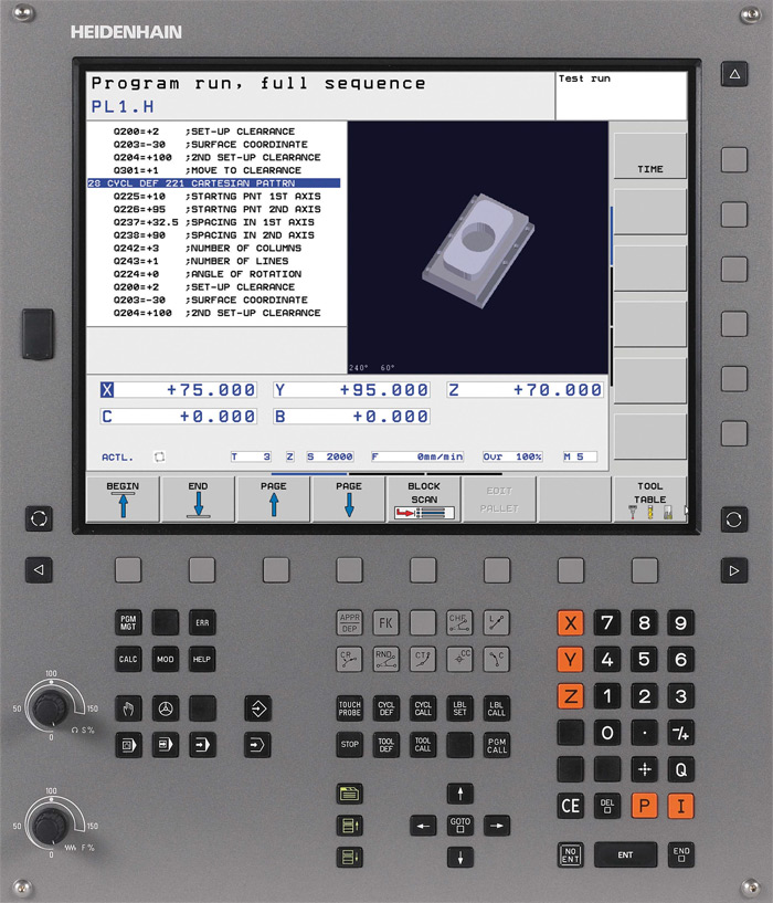


How to understand: will the kitten be fluffy?
What kind of light alcohol can be drunk for pregnant women: the consequences of drinking
Why do the legs swell in the ankles and ankles of the feet in pregnant women: causes and methods of treatment
The wedding of Prince Harry and Meghan Markle: scandalous and secret details of the marriage (photo) The future marriage of Prince Harry year NTV
How to close white plums for the winter