Numerical control (abbr. CNC; English computer numerical control, abbr. CNC) is a computerized control system that controls drives technological equipment including machine tools.
Having decided on the bed, I sat down at the drawings of the machine, initially made them in SPlan7, and why not, the program is universal. It is convenient when there is a drawing with dimensions one to one. I drew a frame, a top view and a side view, drew bearings on the sides, I was able to immediately determine the size of the Z-axis drive screw. Of course, I couldn’t draw everything at once, because, as there weren’t all the installation nodes available - guide shaft supports, linear bearings, drive couplings, axle guide shafts, stepper motors, spindle mounting, bearing support.
The time for orders has begun, stepper motors - Nema23 (23HS6403), ordered with www.duxe.ru, spindle mount (diameter 52mm) and drive sleeves (6.3mm / 8mm) - http://www.aliexpress.com, axle guide shafts, linear bearings in the housing, guide shaft supports, bearing supports were also sharpened according to my drawings on - www.cnc.gollos.com.ua .
As I received the ordered components, I drew them in three views and then used them for drawing in the drawings as elements of the library, very convenient. Gradually, not quickly, the machine was completely built in three projections and now you can shoot any size of interest.
Having decided on running meters and the dimensions of the profile pipes, ran to the metal warehouse. I bought a not easy pack of profile pipes, pulled them home, since they are nearby.
Now we are moving from theory, drawing and procurement, to practice. We need a large list of tools, fixtures and services:
The following operations are defined by each type of torch used and the path of that torch to remove material from the workpiece. Milling machines can be found in a variety of sizes and designs, but still share the same basic components that allow the workpiece to be moved in three directions relative to the tool. These components include the following.
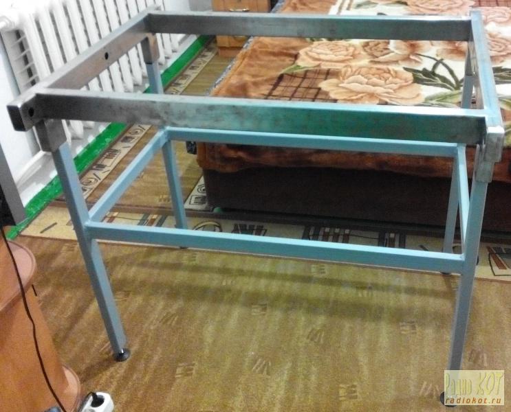
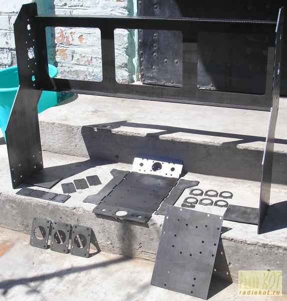
Ready set for machine assembly
The base of the milling machine is simply a platform that sits on the ground and supports the machine. The workpiece can be clamped in a fixture called a vise, which is fixed in T-slots, or the workpiece can be clamped directly into these slots. Saddle - a saddle is a platform that supports the table and allows its longitudinal movement. Knee - The knee is a platform that supports the saddle and table. In most milling machines, sometimes called column and crank milling machines, the crank provides the vertical movement of the workpiece. The knee can move vertically along the column, thus moving the workpiece vertically as long as the cutter remains stationary above it. However, in a fixed bed machine, the knee is fixed and the cutter moves vertically to cut off the workpiece.
- Base and column.
- The large column is attached to the base and connects to the other components.
- Table.
Power tool.
1. Angle grinder, small (500-700W);
2. Electric drill, with speed control;
3. Welding machine, preferably semi-automatic;
Measuring tool, marking.
1. Roulette (2m.);
2. Metal ruler (0.5m.);
3. Square (from 200mm.);
4. Scriber for metal (with winning soldering);
Metal cutting and processing tools.
1. Cutting discs for metal (diameter 125mm, thickness 1.6mm)
2. Cleaning circles (petal);
3. Nozzles abrasive, for a drill (cylindrical, 15-20mm.);
4. Sanding paper (medium and fine);
5. Files for metal (square, flat, circle and semicircle);
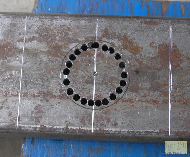
6. Crown for metal, with victorious soldering (diameter 18mm.);
7. Carbide drills, HSS (diameter - 3.5mm., 5.5mm., 10mm.);
Clamping tool and fixtures.
1. Hex keys (4mm.);
2. Open-end wrenches or adjustable (8mm., 22-24mm.);
3. The vise is large;
4. A set of clamps for metal of different sizes (plus home-made ones);
Services.
1. Turning works;
2. Welding work;
3. Laser or plasma cutting of sheet metal;
4. Online stores;
5. Base of metal-roll (profile and sheet metal);
It is also necessary to have “direct hands”, preferably four, a lot of free time and patience.
A horizontal milling machine uses a cutter that is mounted on a horizontal shaft called a arbor over the workpiece. For this reason, horizontal milling is sometimes referred to as shaft milling. The support is supported on one side by a bridge, which is connected to the column, and on the other side by a spindle. The spindle is driven by a motor and therefore rotates the arbor. During milling, the cutter rotates along a horizontal axis and the side of the cutting tool removes material from the workpiece.
A vertical milling machine, on the other hand, orients the cutting tool vertically. The cutter is fixed inside a piece called a collet, which is then attached to a vertically oriented spindle. The spindle is located inside the milling head, which is attached to the column. Milling operations performed on a vertical milling machine remove material using both the bottom and side of the cutter.
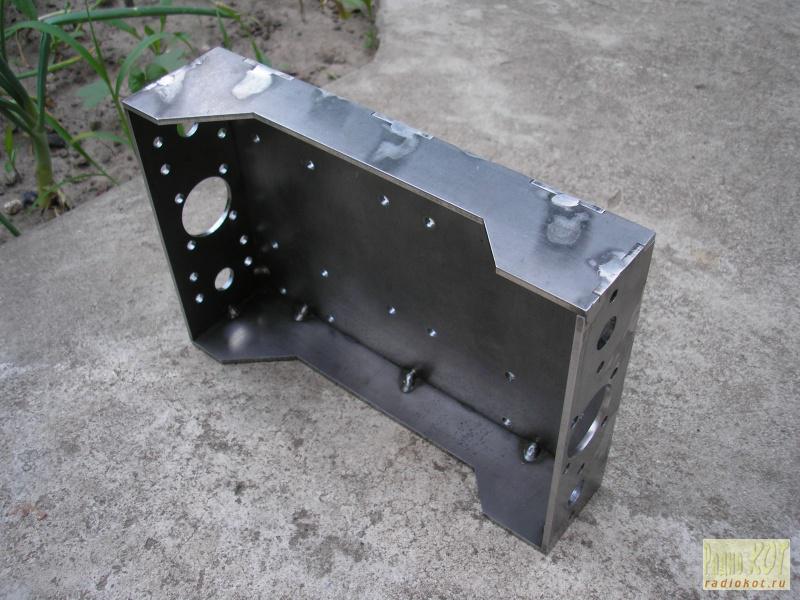
So, let's start with the bed of the Z axis of the machine.
For the frame we use a profile pipe with a section of 30x60x2mm. We need segments: 903mm. - 2 pcs. (longitudinal sections of the bed), 718mm. - 2 pcs. (transverse segments of the bed), 80mm. - 4 things. (bed legs). The bed will turn out to be universal, it can be installed on a table or put on a base.
Milling machines can also be classified according to the type of control used. A manual milling machine requires the operator to control the movement of the torch during the milling operation. The operator adjusts the position of the torch using hand cranks that move the table, saddle and knee. Milling machines can also be controlled by a computer, in which case they are called a CNC milling machine. program management. The angle of the spindle and cutting tool can be changed, allowing even more complex shapes to be milled.
To get pipe segments of the required length, follow the sequence:
1. We take a pipe with a margin in length, on the one hand we make a circular marking for a square;
2. Next, we clamp it in a vice, using an angle grinder, we end the pipe along the marking line, making cuts from each of the four sides of the pipe, and not in one cut;
3. After trimming, we remove the scale inside and outside the pipe with a square and flat file;
4. Check the end of the pipe with a square, on each side, adjust if necessary;
5. After trimming the base edge, using a tape measure, mark the required length and repeat steps 2-4.
The tool required for milling is sharp cutter, which will be rotated by the spindle. The cutter is a cylindrical tool with sharp teeth located on the outside. The gaps between the teeth are called flutes and allow the material chips to move away from the workpiece. The teeth may be straight along the side of the cutter, but are more commonly arranged in a helix. The helix angle reduces the stress on the teeth by distributing the forces. In addition, the number of teeth on the cutter varies. More teeth will provide a better surface finish.
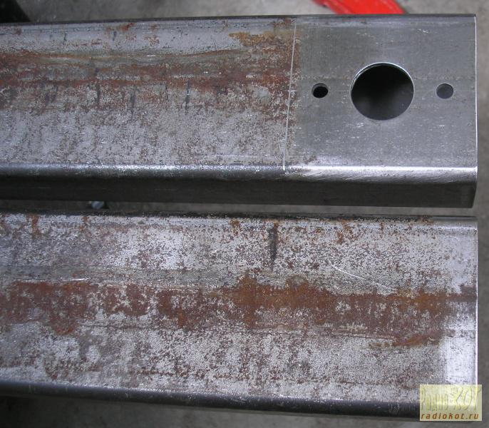
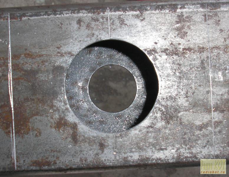
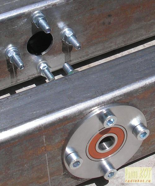
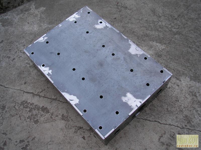
After the performed operations, we proceed to marking the holes on the transverse sections of the frame for the installation of guide shaft supports, drive screw bearings, mounting coupling screws (18mm crown), studs for installing stepper motors. Marked, drilled, now you can carefully clean the surface of the pipes.
The cutters that can be used for milling are very diverse, allowing you to create different functions. While these cutters vary greatly in diameter, length, and cut shape, they also vary in their orientation, whether they will be used horizontally or vertically.
A cutter that will be used on a horizontal milling machine will have teeth that run the entire length of the tool. The inside of the tool will be hollow so that it can be mounted on a gazebo. In this basic form, there are still many various types cutters that can be used in horizontal milling, including those listed below.
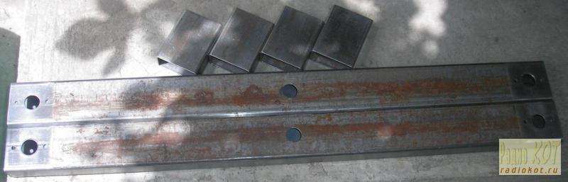
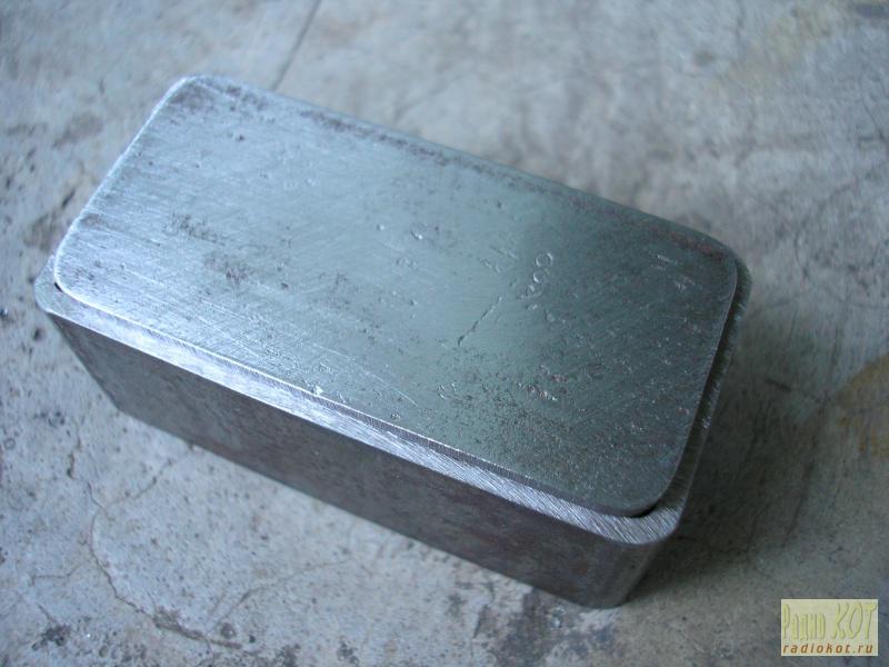
For the ends of the transverse pipes, we will make plugs from pieces of pipes.
Double Angle Tooth Mill Milling Machine. Another operation known as log milling is also possible with a horizontal milling machine. This form of milling refers to the use of multiple cutters attached to the arbor and used at the same time. Slot milling can be used to form a complex function with a single cut.
For vertical milling machines, the cutters have a completely different shape. The teeth of the cutting tool cover only part of the tool, and the remaining length is smooth surface called the tail. The shank is the section of the cutting tool that is fixed inside the collet for attachment to the spindle. In addition, many router bits are designed to cut using both sides and the bottom of the torch. Listed below are a few common vertical cutters.
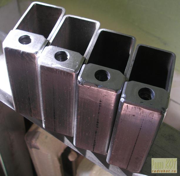
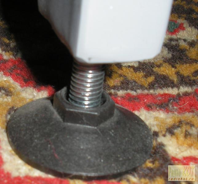
Plates with threads will be welded into the legs of the bed, into which we will screw the adjustable supports.
The same adjustable feet can be rearranged into the base of the machine.
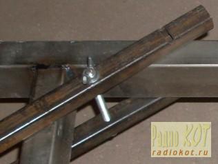
To weld the frame, it is necessary to assemble it on the M16x1000 mounting studs and tighten it at the corners with home-made profile clamps. Clamps are two sections of a profile pipe, 20x30x250mm in size, with 8.5mm holes. in the centers, tied together with studs 150 mm long. and diameter 8mm (M8).
All cutters used for milling can be found in a variety of materials which will determine the properties of the cutting tool and the workpiece materials it is best suited for. These properties include hardness, toughness and cutter wear resistance. The most common cutting materials that are used include the following.
High speed steel Carbide Carbon steel High speed cobalt steel. The torch material is selected based on a number of factors, including workpiece material, cost, and tool life. Tool life is an important characteristic to consider when choosing a cutter, as it greatly affects manufacturing costs. A short tool life will not only require additional tools to purchase, but it will also take time to change the tool every time it gets too worn.
Assembly should be carried out on a square, with measurements of the diagonals of the bed, then tighten all the coupling nuts and once again check the right angles and diagonals.
To transport the bed in this form, I wrapped it with vacuum cling film, because cleaned and sanded metal shows rust stains very well, not only from wet weather, but also from wet and greasy hands.
The cutters listed above often have teeth coated with a different material to provide extra wear resistance, thereby extending tool life. This fluid is used to reduce the temperature of the torch, which can become very hot during milling, and also reduces friction at the interface between the torch and the workpiece, which increases tool life. In addition, by spraying liquid during milling, higher feed rates can be used, the surface can be improved, and material chips can be repelled.
Welding of the frame is carried out in stages:
1. We dismantle the vacuum food film;
2. We check if the angles and sizes of the diagonals have gone astray;
3. We install the frame in a horizontal position, either on the floor or on the welding table;
4. First, we make tacks, dots, cross to cross with bed overturns, let cool;
5. Now, according to the same scheme, we make continuous penetrations, let it cool;
6. With petal, cleaning wheels, we clean the welding seams and see if there are any penetration gaps, if there are, we eliminate them;
7. After cooling, you can remove the clamps from the corners;
8. We pre-weld nuts on the plates from adjustable supports (it can be elongated) and weld them to the legs, clean them, let them cool;
9. We mark the mounting locations of the legs on the bed and fix them on clamps for metal;
10. We grab, boil and clean, let cool;
11. We remove the tie rods and weld the holes from them, since they were auxiliary.
The bed is ready.
Machine on which the milling part is able to move in a vertical direction
Typical cutting fluids include mineral, synthetic and water soluble oils. In milling, the raw shape of the material is a piece of stock from which blanks are cut. This stock is available in various forms such as flat sheets, solid bars, hollow tubes and shaped beams. Sometimes special extrusions or existing parts such as castings or forgings are also used.
Milling can be performed on workpieces made of various materials including most metals and plastics. Common materials used in milling include the following. Aluminum Brass Magnesium Nickel Steel Thermosetting plastics Titanium. . There are several factors to consider when choosing a material, including cost, strength, wear resistance, and machinability. The ability to process the material is difficult to quantify, but it can be said that it has the following characteristics.
The filling of the frame, the “Z” axis, consists of:
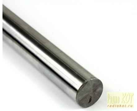
1. WCS linear guide shafts, diameter 16mm, length 1000mm, quantity 2pcs;
- Results with good surface finish.
- Promotes long tool life.
- Requires low force and power for the mill.
- Provides easy chip assembly.
The principle of operation of the milling machine
If the cutting parameters such as feedrate, spindle speed, or are too high, the surface of the workpiece will be rougher than desired and may contain scratches or even burn marks. In addition, a large cut depth can cause the torch to vibrate and cause inaccuracies in the cut. Dull Cutter - As a cutting tool, the teeth will wear down and become dull. Unfinished workpiece. If the workpiece is not securely clamped into the fastener, milling friction can cause it to move and change the desired cuts. An inexpensive workpiece can result in longer cut times and more tool wear, resulting in an increase in overall cost. Minimize the amount of milling required to pre-cut a workpiece close to the desired size and shape. Select a workpiece size such that it is large enough for the workpiece to be securely fastened. In addition, the clamped surface must provide clearance between the tool and fixture for any cut. Minimize the number of setups required when designing all functions on one side of the workpiece, if possible. Design features such as holes and threads require tools standard sizes. Make sure that the depth of any feature is less than the length of the tool, and therefore will avoid the collet making contact with the workpiece. Lower tolerance and surface roughness requirements, if possible, to reduce costs. Expand the inner vertical edges so that the corner radius is the same as the corner radius of the standard tool. If another component with an outer sharp edge needs to fit, drill a hole to provide a bump zone. Avoid very long and thin parts. Use chamfers rather than corner radius for the outer horizontal edges. Avoid undercuts.
- Incorrect cutting parameters.
- A dull cutter is less able to make precise cuts.
- Choose the material that minimizes the overall cost.
- Minimize the number of tools needed.
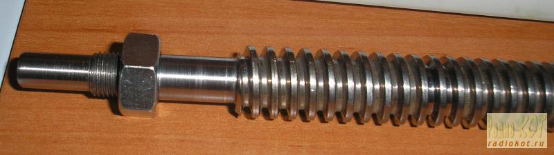
5. Trapezium screw with cutting ends, length 1000mm and caprolon nut;
All fasteners M5, only different lengths.
We continue, the portal is the "Y" axis and the "Z" axis.
The portal and the axis will be made of sheet metal measuring 1000x1000x3mm, by laser cutting, namely laser cutting, because plasma cannot cope with the smallest details. To make parts from sheet metal, you need to draw them in CorelDRAW or AutoCAD, observing a number of requirements:
Technical requirements for drawings for plasma cutting:
1. File formats: AutoCAD, SolidWorks, Kompas (preferably *.dxf);
2. All characters and text must be converted to curves;
3. The distance between the parts is greater than or equal to the thickness of the metal, but not less than 6mm;
4. The distance from the edge of the sheet to the details is equal to the thickness of the metal, but not less than 10mm.
I had to redraw what I drew in SPlan7, in CorelDRAW and then open it in AutoCAD and save it as *.dxf. I don't know how to work in AutoCAD, that's why I'm so wise. Sent the file for cutting. Seven days later, the finished parts were sent by the delivery service. I was amazed at the quality of the cut, the highest class. The portal has been assembled without welding yet, and everything held together like a 3D puzzle.
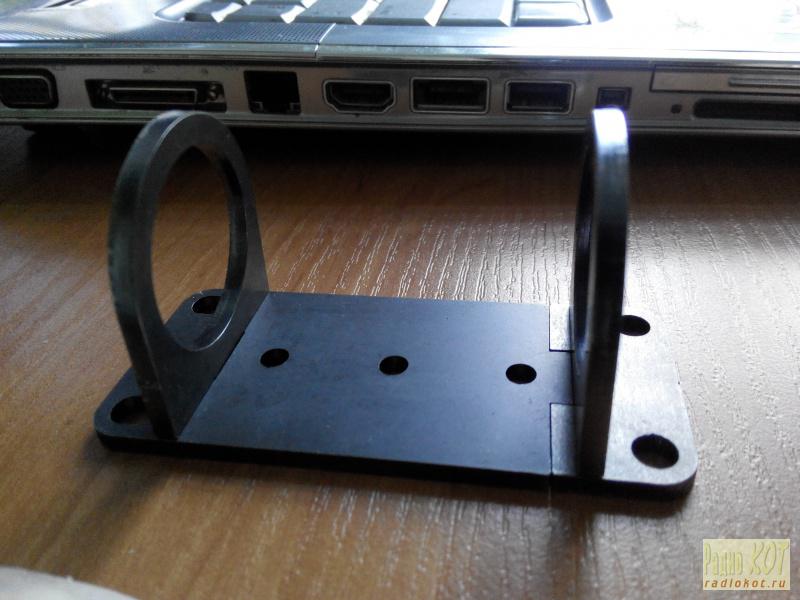
Before welding, the portal was assembled and pulled together with the same M16x1000 studs (through the holes of the guide shafts), and its lower part was fixed with corners through the holes to the chipboard board. Welding of the portal was carried out with bold points in order to exclude the conduct of metal from continuous penetrations. In the place where the nut was attached to the portal, profile pipe 15x15x2mm. After welding, I cleaned everything, not flush, with petal circles, dismantled the tie rods.
The filling of the portal, the “Y” axis, consists of:
1. WCS linear guide shafts, diameter 16mm, length 750mm, quantity 2pcs;
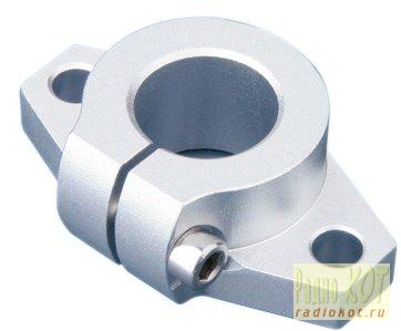
2. SHF shaft holder, SHF16UU, quantity 4pcs;
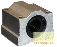
3. Linear bearing in housing, SCS16UU (4 holes), quantity 4pcs;
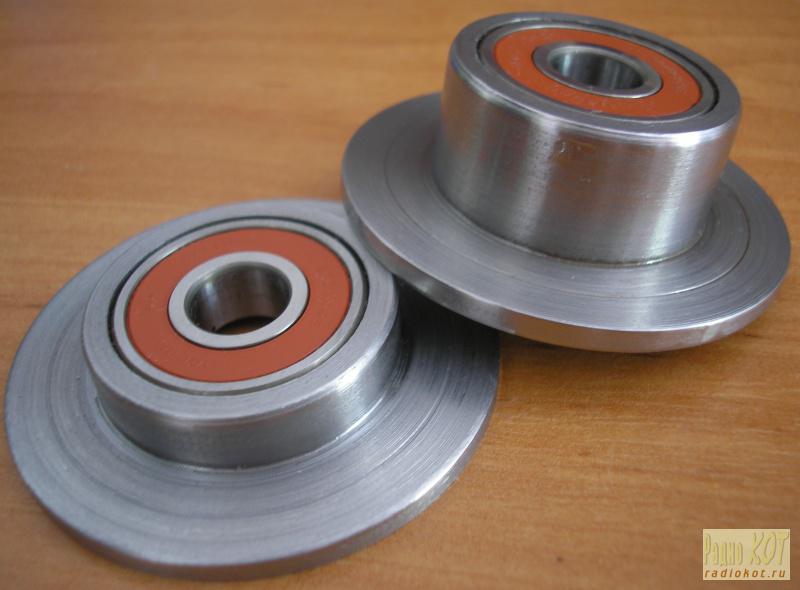
4. Bearing supports (bearing No. 6000 - 3 pcs.), Quantity 2 pcs, turned;
5. Trapezoid screw with cutting ends, length 740mm and caprolon nut;
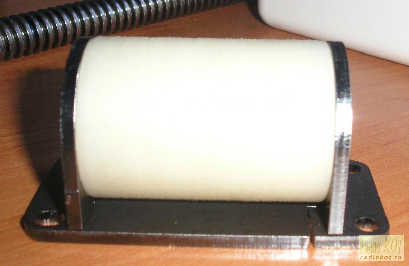
Let us dwell separately on the design of caprolon nuts. I came up with it myself. The nut is inserted into a detachable holder and is locked with thrust cotter pins, with a hexagon head.
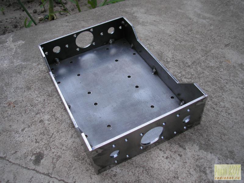
Now the Z axis. For welding, I screwed the "bottom" of the axis, through its holes with screws to the chipboard, so that it would not lead. Then he leaned four walls and pulled them together with clamps. I boiled it, inside in the corners with tacks, and on the outside, each “thorn” in 1-2 places (depending on the width). It cooled down, dismantled the screws and cleaned it (only from the outside).


Who are the victims of the Manchester bombing?
Diana Shurygina ended up in a psychiatric clinic
You can swim for baptism all week
The Martens family from Kyshtovka "is now hiding from everyone" in Germany The German Martens family
University entrance exams What does it mean to be enrolled without entrance tests