It is difficult to overestimate the importance of technological equipment in the organization of complex mechanized machine shops. The technical level of equipment of metal-cutting machine tools determines the efficiency of the technological operation, processing productivity and the accuracy of the parts obtained to the same extent as the quality of the machines themselves. Technological equipment creates the conditions for the transition from the sequential method of processing to parallel and parallel-sequential, and its technical level predetermines the cost of auxiliary time for the removal and installation of the part.
However, if the benefit of using special equipment in large-scale and mass production is beyond doubt, then the widespread use of special equipment in small-scale and mass production can cause unjustified losses. And not so much because of the large material costs for the development and manufacture of tooling, which is important, how much due to the excessive delay in the terms of technological preparation for production. This does not mean, of course, that small-scale production should not be engaged in the technological equipment of machine tools. The lack of tooling increases the installation time of the part several times and affects the quality of the products. Even when switching to CNC machines program management you need to develop mounting fixtures for fixing parts. But work in this direction has its own characteristics.
Technological equipment of small-scale production should be carried out by:
1) development of universal technological equipment and machine tools;
2) the use of reversible tooling designs, which make it possible to assemble special devices from unified elements or assemblies and disassemble them into elements;
3) the use of specialized, including reconfigurable devices for processing structurally similar parts that are in a certain size range;
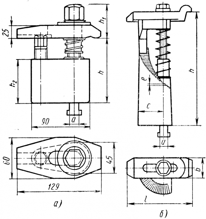
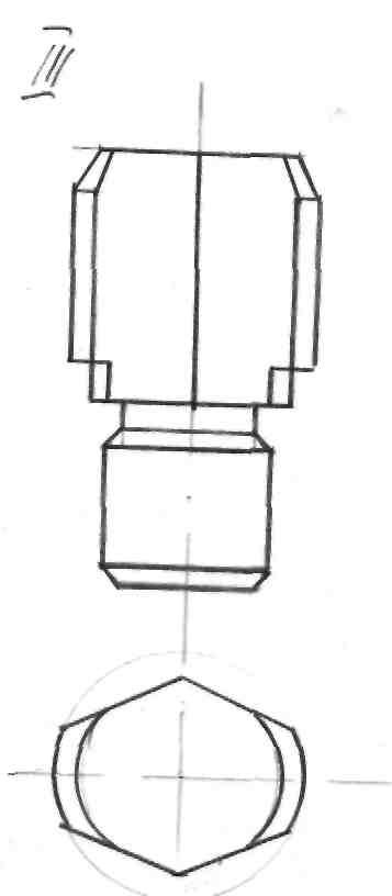
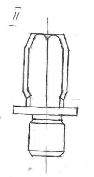
Rice. 57. Screw holders for machine grooves
4) the use of interchangeable adjustments for universal and specialized fixtures for locating the workpiece;
5) the use of universal basing and clamping elements (mechanical, pneumatic, hydraulic, etc.), which allow fixing the part directly on the machine table.
Consider now the series constructive solutions on technological equipment of metal-cutting machine tools.
Universal clamping elements. In single-piece and small-scale production, the processing of parts on milling, boring, longitudinal planing machines is usually carried out without setting devices, and the fastening of parts is carried out with screw clamps. various types, sizes and designs. At the same time, the difficulty lies in the fact that the clamping surface of the part has a different height, the clamp must be “increased”, replacing its screw and support base, the time for fixing the part increases. There are a number of designs of universal screw clamps that allow changing the height of the clamp within certain limits without changing the clamps.
On fig. 57, a and in table. 11 shows screw clamps for machine slots in four sizes: a = 12, 14, 16 and 18 mm. Clamping screws and an adjustable support rod are placed in the tack bodies. The range of adjustment of clamps along the height of the clamping surface is indicated in Table. 11: 40mm (55-95) to 100mm (400-500).
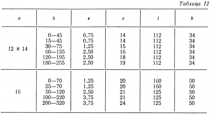
On fig. 57, b shows screw clamps with a support "ladder" for the grooves of the table a - 12, 14, 16 mm. This design of clamps also has a wide range in clamping height: depending on the size, clamps allow clamping parts with a height difference of 0-45, 15-45, 30-75, 60-135 mm, etc. (Table 12).
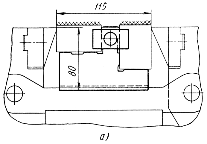
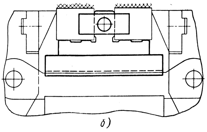
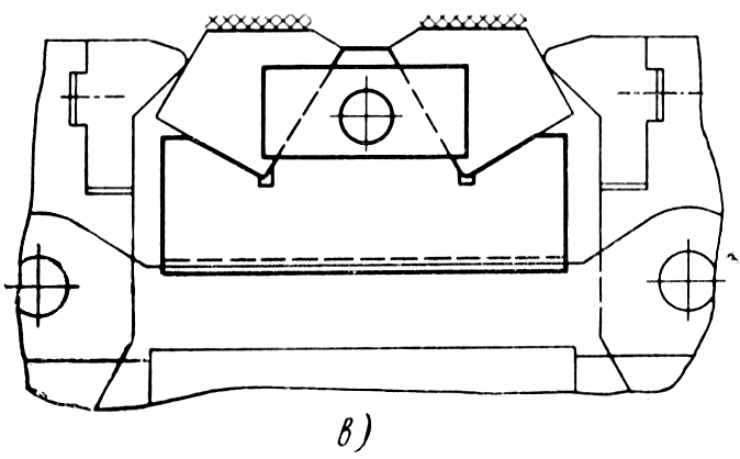
When processing parts such as plates, strips, rails, it is impossible to use a clamp only from above, since this surface is to be processed, they cannot be clamped in a vice due to the size of the parts; in this case, it is advisable to use universal elements in which the main force is directed in the horizontal plane in order to press the workpiece against the stops.
The design and dimensions of these clamps are varied, they are selected depending on the size of the grooves of the machine table and
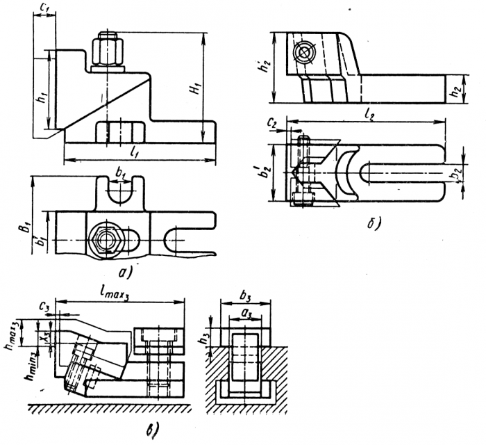
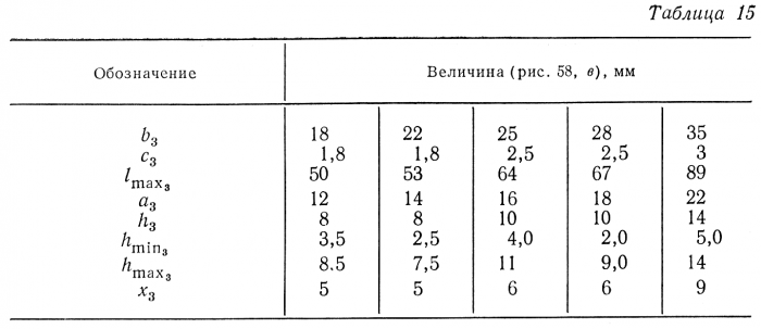
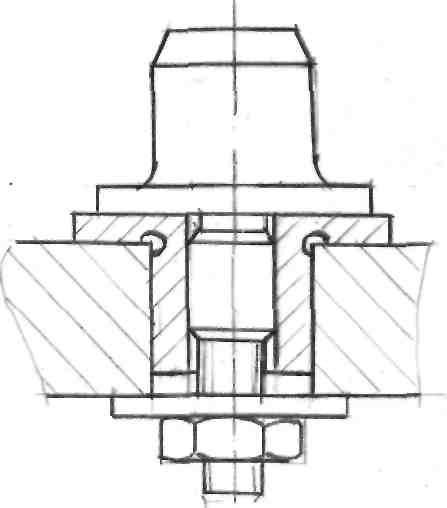
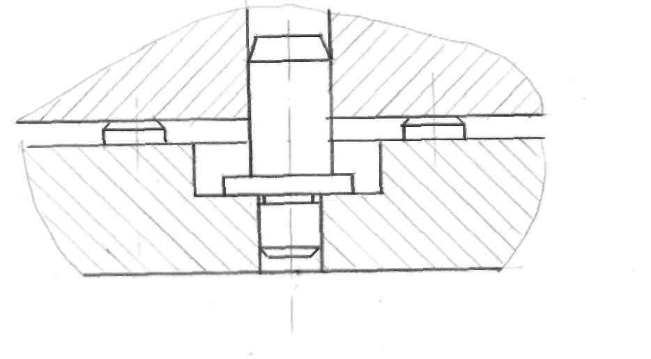
Rice. 58. Universal clamps: a and b - horizontal; c - combined
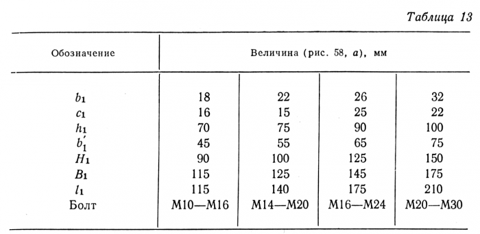
Workpiece heights. Some of these clamps create a force not only in the horizontal, but also in the vertical plane, pressing the workpiece to the machine table (Fig. 58, a-c and tables 13-15).
All types of screw clamps and clamps, for all their versatility, have two main drawbacks: the need to apply significant physical effort to secure and release the part; large losses of auxiliary time for installation, clamping and removal of parts.
The mechanization of universal clamping elements goes mainly along the path of using hydraulic and mechanohydraulic clamps. Drive hydraulic accumulator installations or pneumohydraulic amplifiers supplying oil under pressure of 60-160 kgf / cm 2 for clamps are located either outside the machine and connected to the clamping hydraulic cylinders with flexible hoses, or - for large and heavy machines - directly on the machine table.
![]()
By mechano-hydraulic clamps, it is customary to understand small manual hydraulic pumps for clamping parts, mounted on the machine table, driven by a handle or a key.
Hydraulic clamps have built-in hydraulic cylinders with a diameter of 40 and 50 mm (Fig. 59, a and Table 16) and operate at a pressure of 100 kgf / cm 2. The clamps are made retractable, which makes it easy to remove the workpiece. The design of these clamps has a relatively small clamping height range (45-60 mm), and an adjustable hydraulic clamp is more versatile (Fig. 59, b and table. 16). In this case, the clamping range is determined by the length of the screw on which the clamp and hydraulic cylinder are placed. Adjustment of the position of the clamp in height is carried out with the help of nuts (lower, supporting the spring, and upper), as well as by shifting the stepped support.
To clamp parts in a horizontal plane, hydraulic clamps can be used (Fig. 59, c). The body of the clamp is based in the groove of the table and at the same time serves as a support for the workpiece to be clamped. The clamping force is determined by the diameter of the hydraulic cylinder (40, 50 and 60 mm) and is respectively 920, 1460 and 2070 kgf.
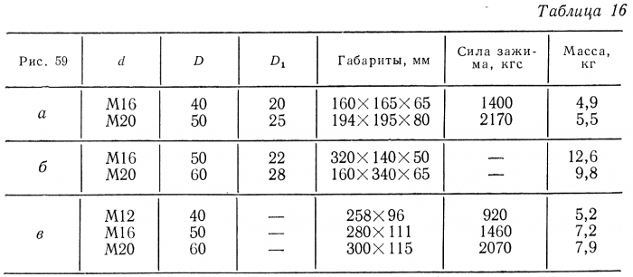
Rice. 59. Hydraulic clamps:
a - with a built-in cylinder: b - height-adjustable clamp; c - horizontal; g - articulated; e - tack with mechano-hydraulic clamp; e - mechanohydraulic nut
A wide range of clamping allows the implementation of hinged hydraulic clamps (Fig. 59, d), developed by VPTITYAZHMASH. The clamp is installed and fixed in the T-slots of the table. The clamping force is transmitted to the clamp by a double-acting articulated cylinder. The working pressure of the oil in the cylinder is 50 kgf/cm 2 . Adjustment of the clamping height in the range from 40 to 220 mm is carried out by rotating the knurled nut.
When fastening parts on heavy metal-cutting machines, the use of group hydraulic installations with wiring to individual clamps causes a pile of hoses and makes it difficult to maintain the machine. In these cases, it is advisable to use mechano-hydraulic devices driven by a handle or a key and having a closed hydraulic system. The relatively small force (2-10 kgf) exerted by the worker on the wrench handle is amplified hundreds of times and reaches 2000-10,000 kgf on the clamp.
On fig. 59, e shows a clamp with a mechano-hydraulic clamp for fixing parts on the tables of heavy longitudinal milling, boring and planing machines. When the screws are rotated with a socket wrench with a handle length of 150 mm and a force of 10 kgf, the hydraulic cylinder creates a force of up to 7500 kgf on the clamp. The piston stroke of the clamping device is 10 mm. The mechano-hydraulic nut (Fig. 59, f) is screwed manually onto the screw until the clamp comes into contact with the clamped part. When the M10 screw is rotated with a socket wrench with a force of 2 kgf, the closed hydraulic system of the nut creates a force on the clamp up to 3750 kgf.
Mechano-hydraulic devices can also be used to power hydraulic clamps. special devices.
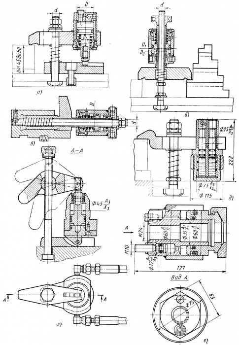
Universal assembly equipment. In the presence of a wide range of standard parts, universal prefabricated fixtures (USP) make it possible to replace up to 70-80% of special equipment, which not only reduces costs, but also reduces the time for technological preparation of production. USP are effectively used in single and small-scale production. The main disadvantage was the absence of mechanized (hydraulic, pneumatic, etc.) clamps in their designs. This increased the time to install and remove the part, and in the conditions of serial production, factories often went to the use of special, albeit more expensive, equipment. In recent years, a number of additional USP elements have been created that allow mechanizing the workpiece clamping.
For various branches of mechanical engineering, three standard sizes of sets of parts for USP have been developed, standardized and manufactured, which differ in the diameter of the fastener, the width of the grooves and overall dimensions basic elements.
1. A set of parts for universal prefabricated fixtures with a groove width of 8 mm for processing small parts (220x120x100 mm). The design and dimensions of USP-8 elements are regulated by GOST 14582-69-GOST 14607-69.
2. A set of parts for universal prefabricated fixtures with a groove width of 12 mm for processing medium-sized parts
(700x400x200 mm). The design and dimensions of USP-12 elements are regulated by GOST 15436-70-GOST 15465-70. Two versions of this kit are available: a start-up kit for small plants with little machining and an advanced kit for plants with a large amount of machining.
3. A set of parts for universal prefabricated fixtures with a groove width of 16 mm for processing large parts (2500 X X2500X 1000 mm). It is applied at factories of heavy mechanical engineering. The design and dimensions of USP-16 elements are regulated by GOST 15636-70-GOST 15761-70.
A number of USP-8, USP-12, USP-16 elements and elements of a universal prefabricated reconfigurable equipment of a different type, for example, universal prefabricated overhead conductors, reconfigurable mechanized units, etc., are interchangeable. This expands the scope of devices.
The main data of the sets USG1-8, USP-12 and USP-16 are given in Table. 17 (according to the materials of the Soyuztekhosnastka MGKTB). A further development of the USP is the system of reconfigurable universal prefabricated fixtures (PUSP), developed by the Soyuztekhosnastka MGKTB. The PUSP set is a set of non-separable units, including mechanized quick-acting clamps, from which various devices for milling, boring, planing, drilling and other works are assembled.
PUSP elements allow the installation and fastening of workpieces directly on the machine table. The PUSP kit includes basic and clamping units and pneumohydraulic drives. The basic non-separable units include hydraulic vices, a plate with a pneumatic drive, hydraulic blocks, which are a plate with several hydraulic cylinders. Clamping elements are hydraulic cylinders, eccentric clamps, universal clamps and parts for their installation and fastening in various positions. Eccentric clamps are also used for fast workpiece clamping with low cutting forces. In the PUSP kit, preference is given to non-separable units, which speed up the process of assembly and reconfiguration of layouts, reduce the number of joints, which increases the rigidity of the fixture and the accuracy of processing.
The drive of hydroficated PUSP elements is carried out from a pneumohydraulic booster that converts compressed air pressure (4-6 kgf / cm 2) into high (100-150 kgf / cm 2) oil pressure, which makes it possible to obtain the necessary clamping forces at a relatively small sizes hydraulic cylinders.
The connecting dimensions of the base parts of the main units of the PUSP are interconnected with the existing sets of universal-assembly fixtures with a groove of 12 and 16 mm (USP-12, USP-16), which makes it possible to expand the possibility of using USP by assembling high-speed mechanized fixtures for processing large batches of parts. Such fixtures can replace a number of special fixtures in serial production and group processing of parts, where USP was not usually used.
PUSPs expand the technological capabilities of USPs and have a number of advantages that allow them to compete with high-speed mechanized special or permanent group devices used in mass production.
The time for the initial assembly of fixtures and their readjustment is reduced due to the use of non-separable units. Using non-separable units in the transition from processing one part to another, it is possible to replace the assembly with the readjustment of an already assembled device, which requires 3-4 times less time.
The presence of PUSP allows the use of a group processing method with frequent changes in production facilities and a wide range of machined parts, since group fixtures can be assembled from the PUSP kit, which, after completion of work, are readjusted for processing another group of parts.
Universal machine equipment. In small-scale production for drilling holes in cylindrical workpieces
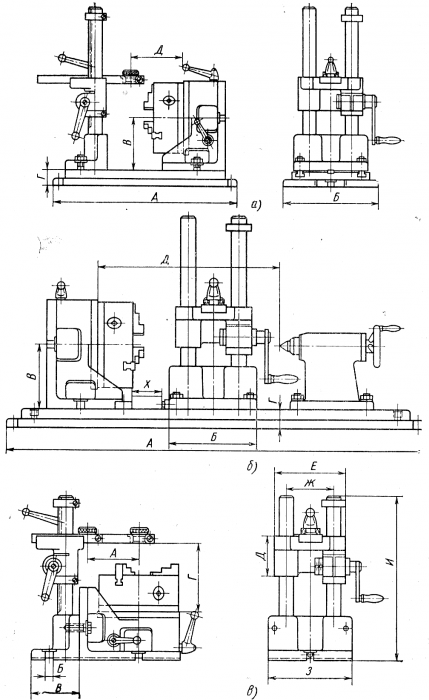
Rice. 60. Universal jig for drilling parts clamped in a three-jaw chuck:
a - with cantilever fastening; b - with additional support by the center; in - from the side of the end
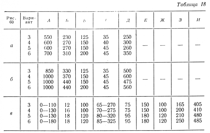
with an accuracy of about 0.1 mm - it is advisable to use universal conductors. Universal conductor firm "Schmidt-Costa", shown in fig. 60, a (Table 18), allows you to fix the part in a three-jaw chuck mounted on a dividing faceplate. An adjustable bar with a replaceable conductor sleeve moves vertically on two posts.
This jig allows you to drill, countersink and cut threads in holes located on the outer surfaces of cylindrical parts.
On fig. 60, b shows a similar jig with fixing parts in a chuck with support rear center.
For processing along the ends of cylindrical parts such as flanges, covers, glasses, a universal jig of the same company is used (Fig. 60, c). The dividing faceplate of the conductor, bearing on itself three-jaw chuck, allows you to get the angular arrangement of the holes, and the movable bar with a drill bushing provides the necessary offset of the holes from the center of the part.
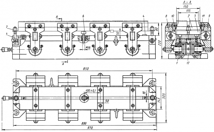
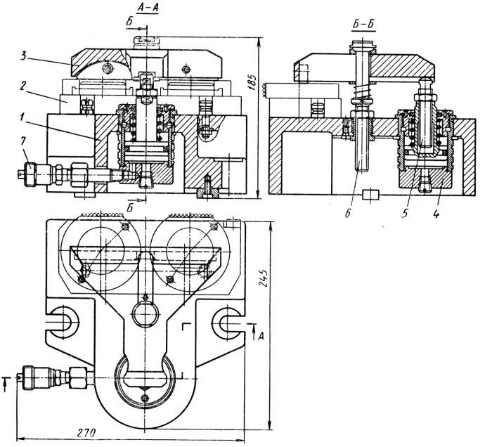
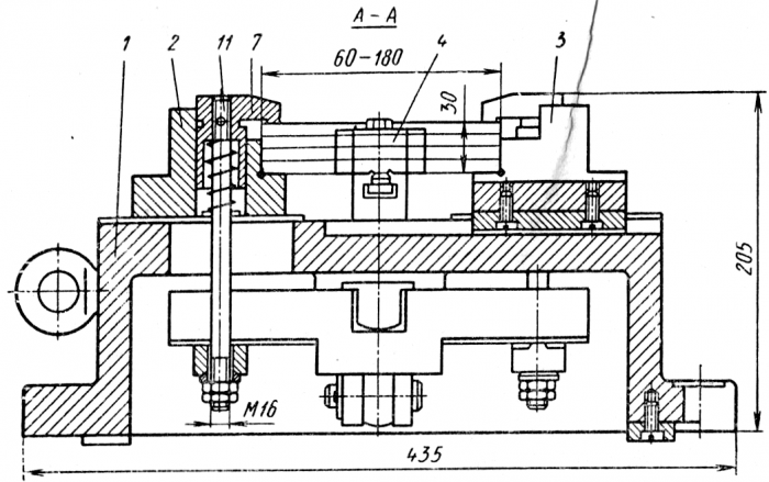
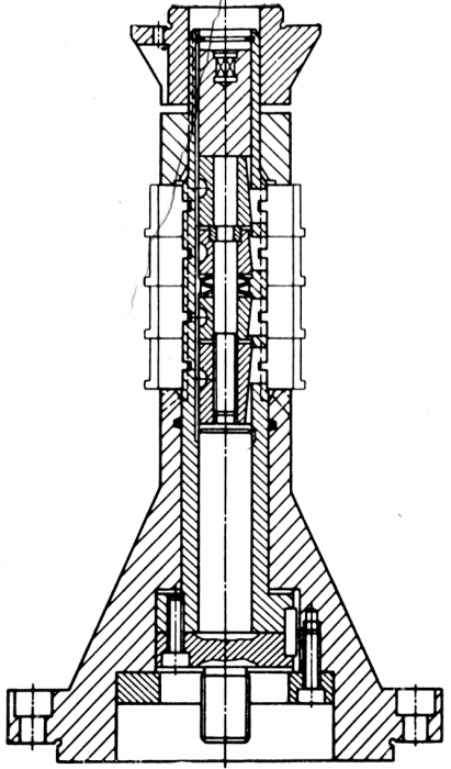
With an increase in the scale of production, as well as for precise work, the above types of universal conductors are inferior to rock conductors with special adjustments, as well as the simplest special conductors (for example, invoices). It is advisable to combine the use of special conductors with a universal device for their fastening. On fig. 61 shows a fixed table 1 (pedestal) with a pneumatic clamp 2 to the radial drilling machine. Parts or conductors for drilling holes are attached to the table on plate 3. The clamping force is transmitted from the pneumatic piston 4 through the threaded sleeve 5 connected to the piston rod and the screw 6. At a network pressure of 5 kgf / cm 2, the force developed by the pneumatic cylinder reaches 1500 kgf.
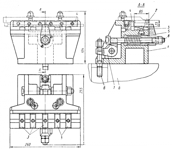
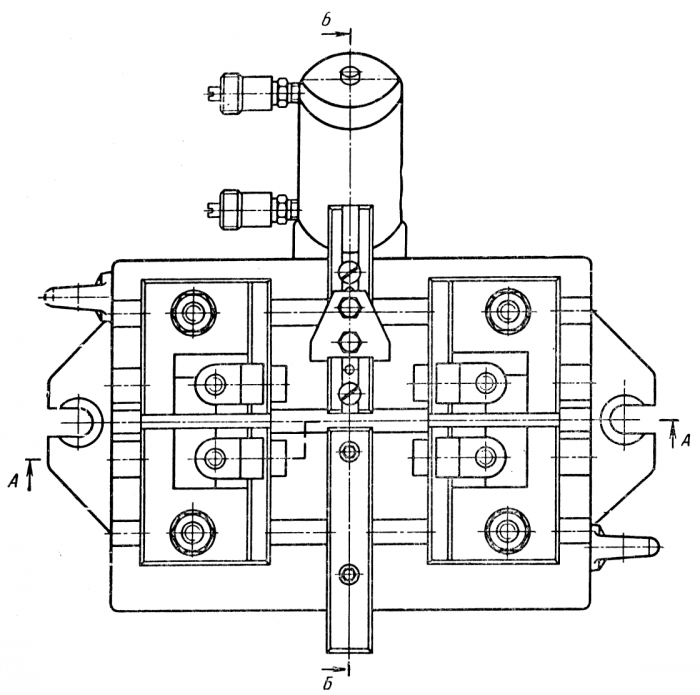
On fig. 62 shows a specialized setting tool for drilling parts such as strips, mounted on a table with pneumatic clamping. The device consists of a basic
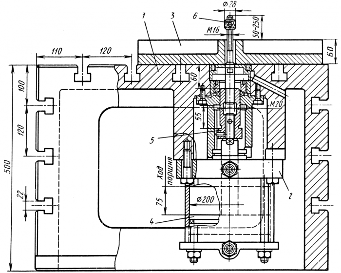
Rice. 61. Table with pneumatic clamp to a radial drilling machine (pneumatic stand)
part 1, fixed on the table B (pedestal), and interchangeable adjustments - jig plates 2. The workpieces are mounted on the support strips 3 and pressed against the strips 4 with a clamp 5. The clamping force is transmitted to the clamp 5 from the pneumopressure of the cabinet through the pin of the bar 6, the lever 7 and bolt 8.
The most common type of universal machine tools are rotary dividing tables and racks with vertical and horizontal axes of rotation. They are made in various sizes and types, with varying degrees of division accuracy, with manual, pneumatic, hydraulic and electric drive, with automated and non-automated work cycle. Universal dividing tables and racks are used to perform various operations on vertical and radial drilling, milling and boring machines, and also built into the design of modular machines (especially small sizes). The most promising are dividing tables, in which dividing and fixing are carried out by two flat gear wheels (Fibro company), providing a dividing accuracy of ± 3 ". Dividing tables with a pneumatic drive and a ratchet rotation and fixation mechanism, similar to the table shown in Fig. 63. This table can work in automatic cycle.
Rice. 62. Specialized setting device for drilling parts such as strips on a table with pneumatic clamping
Rice. 63. Dividing table Ø 250 mm with pneumatic drive of the dividing mechanism
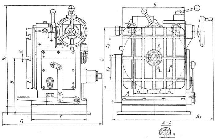
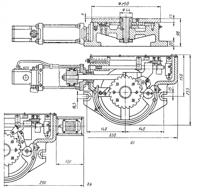
Rice. 64. Dividing stand with faceplate 800X800 mm
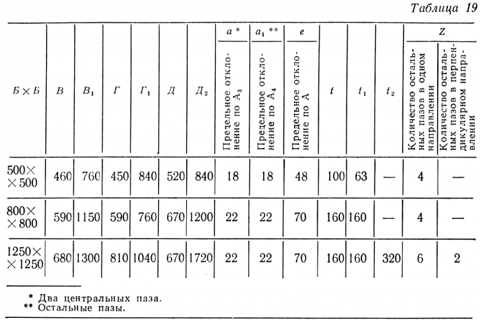
For drilling and boring work performed on radial drilling machines, in fixtures with tool guidance, rotary dividing racks developed by Orgstankinprom with a horizontal axis of rotation and faceplate sizes of 500x500, 800x800 and 1200x1200 mm are widely used. Racks are made single- and double-support, which allows you to install various clamping devices or workpieces on them cantilevered (or with support). The rotary part of the rack is driven by an electric motor through a gearbox; the stand automatically locks after 90° of rotation. The faceplate can be stopped in any other position and locked manually. The accuracy of division with automatic fixation of the faceplate is 3". This relatively low accuracy is compensated by the fact that the tool, having freedom in the quick-change chuck, is guided along the fixture bushings.
On fig. 64 shown general form dividing stand with faceplate 800x800 mm. The rack is controlled by a foot pedal. The rack is mounted at the pit, which allows turning parts with dimensions exceeding the dimensions of the faceplate. The main dimensions of the dividing racks are given in table. nineteen.
Specialized fixtures. The unification of the geometric elements of parts creates conditions at the enterprise for combining structurally similar parts into groups that have the same shape and differ only in size or additional elements (holes, grooves, bald-
us, etc.). At the same time, such advantages of special adjustment devices as the accuracy of basing and the speed of installation of the part are preserved, and the possibility of changeover to a group of structurally similar parts is added. Specialized adjustment devices are used for milling, drilling, boring and other work. On fig. 65 shows a specialized setting tool for milling the planes of parts such as strips and wedges on a vertical milling machines. The device consists of a base part 1 (with built-in hydraulic clamps) and interchangeable adjustments 2. An intermediate plate 3, used to reduce the height of the adjustments, is installed on the upper plane of the base part along the dowels 4 and fixed with screws 5, 6 and nuts 7. Simultaneous fastening of two machined parts is carried out by four interlocked clamps 8 and 9. Interchangeable inserts 10 and 11 are used to reduce the clamping size. The clamping force is transmitted to the clamps from two-piston hydraulic cylinders 12 single-acting. The device allows the processing of parts with a length of 100 to 800 mm, a width of 50 to 80 mm and a height (thickness) of 18 to 50 mm. On fig. 66, a-c are examples of interchangeable adjustments for the fixture shown in fig. 65.
A specialized setting tool for milling the flats of flanges and covers is shown in fig. 67. The device consists of a base part 1 with a built-in hydraulic clamp and replaceable adjustments 2 installed on the upper plane. The workpieces are fastened with a clamp 3,
Rice. 65. Dedicated setting tool with built-in hydraulic clamps for milling parts such as slats and wedges
Rice. 66. Interchangeable setups for a device for milling strips and wedges (crosses show the surface to be machined)
Rice. 67. Specialized setting tool for milling flange flats (crosses show the machined surface)
transmitting the clamping force from the piston of the single-acting hydraulic cylinder 4 through the adjustable bolt 5. Depending on the height of the workpieces, the vertical position of the clamp is adjusted by bolts 6 and 5. Liquid is supplied to the cylinder through the fitting 7.
Interchangeable adjustments to the device allow processing parts with a diameter of 50 to 100 mm and a height of 15 to 60 mm.
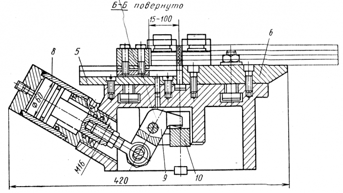
As an example of a specialized device that does not require interchangeable adjustments, in Fig. 68 shows a device for cutting parts such as slats. The device consists of a base part 1 with built-in clamps and adjustable setting elements: bars 2, 3 and a stop 4. Changeover of the device is carried out by rearranging the bars 2 and 3 in the grooves of the body 1, as well as shifting and adjusting the position of the stop 4, which moves along the groove of the bar 5. The parts to be cut are installed on the protrusions of the slats 2, 3 and the slats 5, 6.
The clamping force is transmitted to the clamps 7 from the double-acting hydraulic cylinder 8 through the lever 9, the bar 10 and the studs 11.
To drill a group of parts such as flanges, a specialized setting tool is used, shown in fig. 69. The device consists of a plate 1, a rotary part 2 and interchangeable adjustments 3. Adjustments are designed individually for each workpiece. They consist of a support part for centering the part and an overhead jig. Adjustments are installed on the upper plane of the fixture along the cylindrical shank of the plunger 4. When the handle 5 is turned, the eccentric shaft 6 through the plunger 4 and the rod 7 fixes the workpiece 9 together with the adjustment on the fixture body.
The conductor is fixed on the table of the vertical drilling machine, and the part is brought to the spindle axis by handle 8, which moves the rotary part along with the adjustment.
The dimensions of the parts machined with this device must not exceed 200 mm along the maximum flange diameter, along the flange protrusion on the other side must have a diameter of at least 30 mm with a total part thickness of not more than 120 mm.
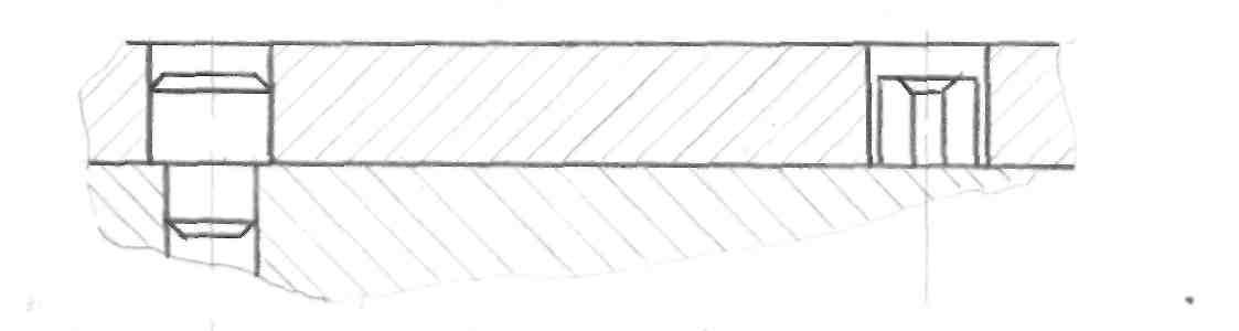
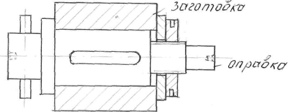
Precision expanding mandrels. When machining parts such as bodies of revolution with precise central holes (gear wheels, bushings, rings, etc.), there are two fundamentally different directions in the construction of the technological process: final processing of the outer and inner surfaces of the part in one setup or processing of one of the surfaces on the base finished other surface. Since in most cases it is not possible to finish the outer and inner surfaces in one setup, tooling is of great importance for precise centering of the part during finishing. The greatest accuracy is achieved when the part is mounted on a rigid mandrel with a taper of 1: 100, which is used in tool and repair shops.
Rice. 68. Specialized device for cutting parts such as planks (the place of the cut is shown by crosses)
Rice. 68 (continued)
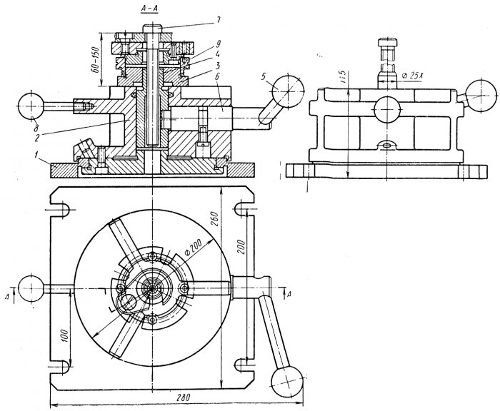
Rice. 69. Specialized setting tool for drilling parts such as flanges
However, when the part is installed on a conical mandrel, the constant position of the part in the axial direction is not ensured. In addition, the installation and removal of parts on such mandrels is performed manually. For these reasons, the most promising is the use of expanding mandrels, which have a number of advantages over rigid ones: the speed of removal and installation of the part when automating this process, the constancy of the axial position of the parts, the possibility of basing on a hole made according to 3-4 accuracy classes.
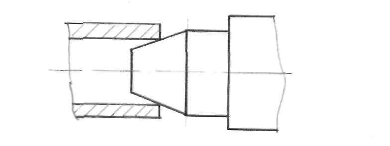
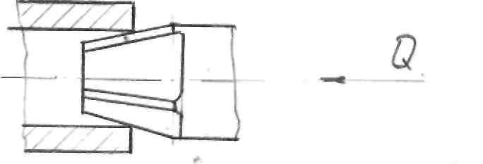
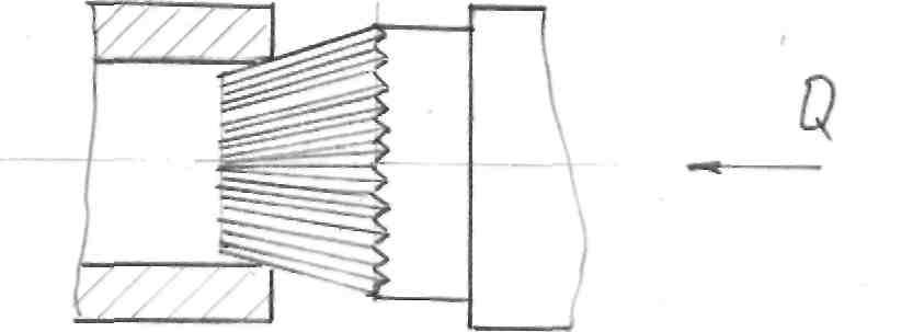
Precision machining fixtures include mandrels with corrugated bushings designed for machining parts such as rings, bushings and sleeves. The centering clamping element of the mandrel (corrugated sleeve) is loaded with axial compressive force and deformed. Wherein inner diameter corrugated sleeve decreases, and the outer increases. The inner surface of the corrugated sleeve is precisely centered and fixed on the mandrel shaft, and the outer surface accurately centers and secures the workpiece.
The amount of axial compressive load that must be applied to the corrugated sleeve to center and secure the workpiece depends on the size of the sleeve. For example, for a bushing with dimensions D = 20 mm and L = 20 mm, this load is Q = 220 kgf; at D = 50 mm and L = 30 mm Q = 600 kgf; at D = 100 mm and L = 50 mm Q = 1600 kgf.
Experimental studies and production observations show that when using mandrels with corrugated bushings, the radial runout of the machined outer surfaces of the workpieces can be maintained within the 2-4th degree of accuracy according to GOST 10356-63. Thus, mandrels with corrugated bushings are the most accurate among modern self-centering clamping fixtures. According to the achieved accuracy of workpiece centering, only stepped cylindrical mandrels are similar to them. However, when using stepped cylindrical mandrels, a selective selection of workpieces is inevitable, while mandrels with corrugated bushings allow processing workpieces with deviations in the diametrical dimensions of the base holes within 1-2 accuracy classes (depending on the nominal value of this diameter).
The material for the manufacture of corrugated bushings is steel grade 60S2KhFA according to GOST 14959-69, hardness after hardening HRC 42-46. Steel grades 60C2A and 65C2VA are allowed for bushings with dimensions D = 19.99 ÷ 39.98 mm and D = 84.968 ÷ 94.968 mm; steel grades 60C2A, 65C2VA, 50HFA and 60C2 for bushings with dimensions D = 44.98 ÷ 54.97 and D = 99.968 mm; steel grades 60S2A, 65S2VA, 50HFA, 60S2, 55S2, 55GS and 65G for bushings with dimensions D = 59.07 ÷ 79.97 mm.
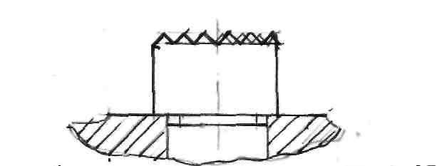
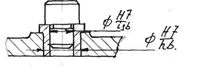
To ensure high centering accuracy of workpieces, the mandrel with corrugated bushings must be made very accurately.
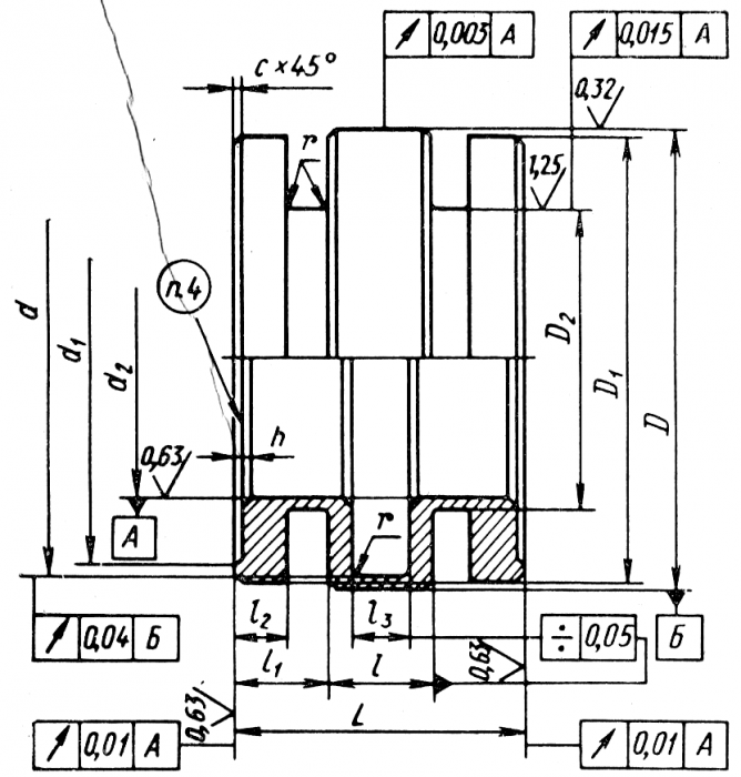
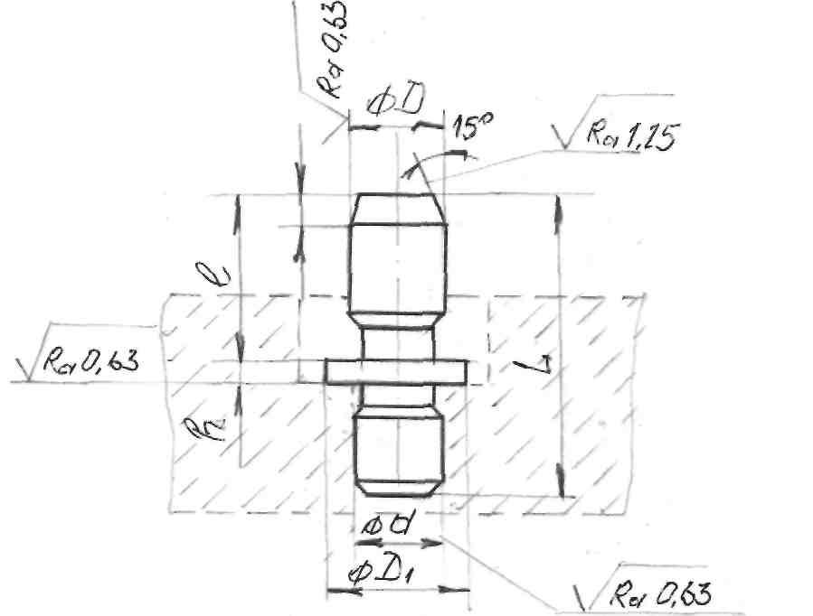
Rice. 70. Basic technical requirements to corrugated bushings for precision mandrels
Basic requirements for dimensional and geometric parameters bushings are shown in fig. 70. The runout of the mandrel shaft should be maintained within the 1st-2nd degree of accuracy in accordance with GOST 10356-63. During operation, mandrels with corrugated bushings wear out, which reduces the accuracy of centering blanks by an average of 3-5 microns for every 25-30 thousand fixtures.
The use of mandrels with corrugated bushings, along with the height of the centering accuracy, makes it possible to obtain a high roundness of the machined surfaces of parts, including thin-walled ones. This is due to the fact that the workpiece fixing force by corrugated bushings is evenly distributed around the circumference of the base hole. The deformations of the workpieces under the action of such forces are uniform and do not cause out-of-roundness. In this respect, mandrels with corrugated bushings compare favorably with cam, collet, and wedge-plunger devices with concentrated clamping forces.
In real workpieces, the base holes are always non-circular. When using mandrels with corrugated bushings, the non-roundness of the base holes of the workpieces is transferred to the machined outer surface. However, the non-roundness of the machined surface can be reduced by about 2.5 times compared with the non-roundness of the base hole.
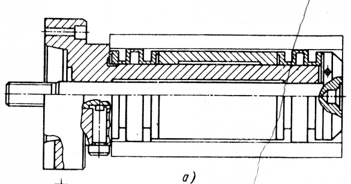
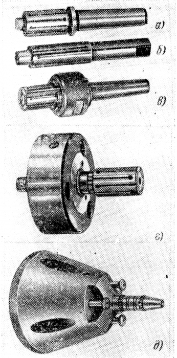
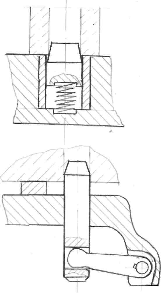
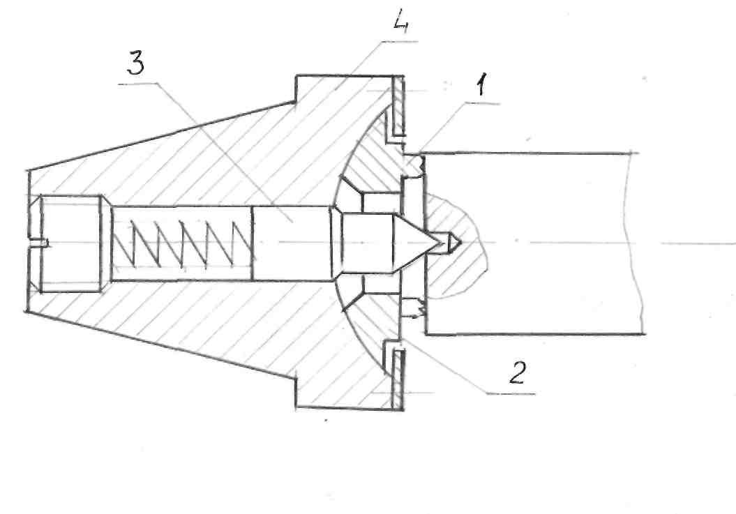
Rice. 71. Mandrels with corrugated bushings: a - center; b - flanged; c - cantilever (Morse cone 1)
Mandrels with corrugated bushings provide transmission of torques and shear forces at finishing operations, have relatively small diametrical dimensions and simple design, can be made on universal metal-cutting machines. When using pneumatic, hydraulic or electromechanical clamping, the mandrels are fast acting. Mandrels with corrugated bushings can have a center, flange or cantilever design (Fig. 71) and serve to secure workpieces with solid, intermittent, stepped or blind base holes.
Corrugated bushings should be deformed only within the limits of elastic deformations. Therefore, the greatest stresses arising in the sleeve during the operation of the mandrel must be less than the yield strength σ 0.2 of its material. This condition is ensured by using appropriate materials and heat treatment of the bushings.
Calculations of geometric, power and strength parameters of corrugated bushings are carried out using the methods of applied theory of elasticity. The calculation method was developed at the Moscow State Technical University. N. E. Bauman Ph.D. tech. Sciences A. A. Shatilov.
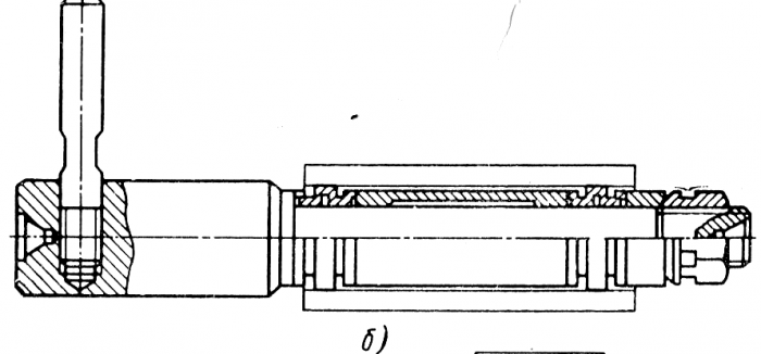
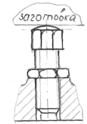
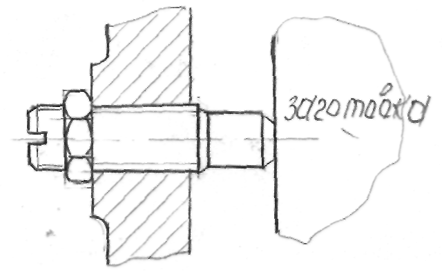
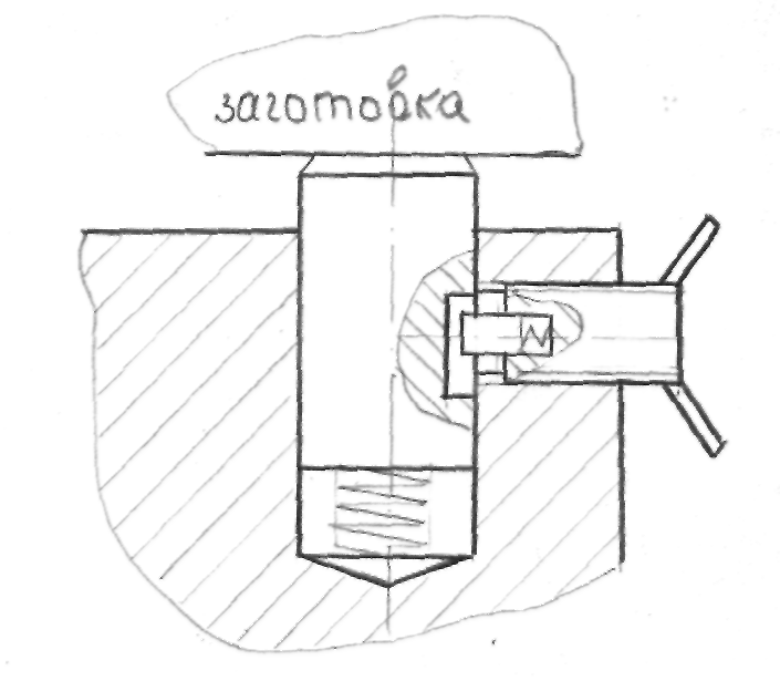
One of the most accurate spreading mandrels is the range of mandrels of the specialized company Tobler (France), some of which are shown in Fig. 72. Cantilever expanding mandrel with collet expansion using a key (Fig. 72, a) provides a centering accuracy of 0.02 mm.
The center expansion mandrel (Fig. 72, b) is used in individual production. The two-sided location of the grooves in the collet provides a spreading range of up to 4-5 mm with a centering accuracy of 0.02-0.03 mm.
For cantilever mandrels (Fig. 72, a and d), clamping is carried out either with the help of a round nut (Fig. 72, c), or with the help of a rod connected to a hydraulic or pneumatic cylinder.
The collet chuck (Fig. 72, e) has retractable end stops, which make it possible to machine both ends of the part in one installation.
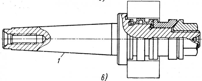
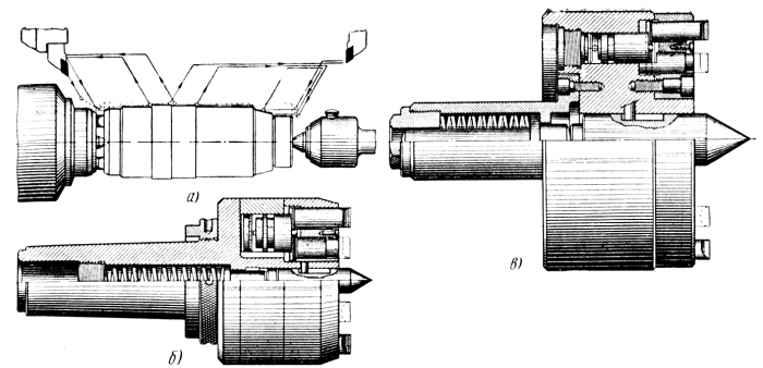
When cutting a package of several gears on gear hobbing machines, the installation of parts is usually carried out on cylindrical mandrels, which leads to inaccurate centering of individual parts in the package. Tobler has created an expanding mandrel for hobbing machines (Fig. 73), where each of the clamped parts is centered by a separate expanding collet. For particularly precise operations, as well as for the control of precision parts, expandable mandrels with hydraulic plastic (the design is patented by Tobler) can be used, providing a centering accuracy of 0.002-0.004 mm.
Face leash cartridges. For turning parts such as shafts, it is advisable to use face-driven chucks that replace collars and cam-driven chucks. The use of cartridges of this type allows you to grind all external surfaces in one installation. stepped shaft, which is especially effective when machining shafts on multi-slide CNC lathes, including those with a working movement of the tool in the direction of both the front and tailstock (Fig. 74, a). Face driving chucks can have different designs: for installation in the spindle cone and for mounting on the flange (Fig. 74, b and c).
When the part is installed on the center of the chuck and pressed with the tailstock, the floating center is shifted until the end of the part stops against the driving pins. To compensate for a possible distortion of the end of the part, the rear end of the driving pins rests on a damping pad.
The torque transmitted by the end driver chuck depends on the ratio of the diameter of the driver clamp to the largest diameter of the part, which must be at least 1: 2; downforce generated by the rear center; processed material and its mechanical properties; direction of feed movement (when feeding from the spindle to the tailstock, the calculated clamping force must be doubled).
Rice. 72. Precision expanding mandrels from Tobler (France):
a - cantilever mandrel with a key clamp; b - center mandrel; in - cantilever mandrel with unclamping by hand; g - mechanized chuck with flange mount and expanding collet; d - mechanized cartridge with retractable stops
Rice. 73. Expanding mandrel firm "Tobler" (France) for gear-cutting machines
For reliable operation driving cartridges, it is necessary that the misalignment of the end of the parts on the circle of the location of the leads does not exceed 0.1 mm (compensated by a damper), therefore it is better to grind or countersink the ends of the workpieces, rather than milling. Sharpening of driving pins should be carried out only in a complete set - one size, with fluctuations in length not more than 0.01-0.02 mm.
Multi-size collets. Clamping collets for turret machines, lathes and turret machines, as a rule, allow fluctuations in the diameter of the fixed bar no more than 0.1-0.2 mm. For this reason, machines of this type must have a large range of clamping collets that are replaced when setting up the machine. In the conditions of small-scale production, it is effective to use multi-dimensional clamping collets of the type of collets manufactured by Pratt-Barnerd (England).
Rice. 74. Schmid-Kosta end chucks:
a - a scheme of turning a shaft in one installation using a face driver chuck; b - the design of the cartridge installed at the end of the spindle; c - design of a driving chuck with a flange mount
The collets of this company differ from the known types of clamping collets: the collet body does not deform during operation, and the clamping is carried out by six movable inserts that have radial movement in the grooves of the collet. Each standard size of such a collet, without changing the inserts, provides clamping of a bar or piece workpiece in the diameter range of 2.5-3.0 mm. So, for example, the first collet size provides clamping of a bar Ø 1.6-4.8 mm, the following collet sizes cover diameters 3.2-6.4; 6.4-9.5; 9.5-12.7; 12.7-15.9 mm, etc. The use of multi-size collets on turret machines, on single-spindle bar machines, on lathes and operating machines that perform second operations, reduces the set of clamping collets by several times and reduces the time for equipment changeover. In some cases, the use of multi-dimensional clamping collets makes it possible to switch to the processing of hot-rolled material instead of calibrated material.
Literature used: "Integrated mechanization and automation in machine shops" authors: Zhdanovich V.F., Guy L.B..
Download abstract: You do not have access to download files from our server.
At any modern enterprise, technological equipment is used. The result of production and the quality of products directly depend on what quality it possesses, and on the timely equipping of all necessary jobs with it. What is it connected with? Reducing the time to perform manual operations can reduce labor intensity, significantly increase reliability and accuracy during production. finished products. Such technological equipment at the enterprise allows minimizing the production of defective products, simplifies the production process and increases labor productivity. It also forms the basis for multi-machine production.
The production and design of technological equipment is a rather laborious process. Here it is necessary to constantly apply the most advanced and modern achievements of science and technology. Modern requirements that apply to the entire machine-building field of activity require a better approach directly to the production process. That is why the production of technological equipment is divided into several main stages:
- Coordination and signing of all necessary contracts for the supply of maintenance.
- Development of technological equipment.
- Her design.
- Modernization of products if necessary.
- Delivery and handover to the customer.
- Signing of all acceptance documents.
- Technical support throughout the entire warranty period.
Manufacturing tooling is carried out by highly qualified specialists in specially designed systems such as CAD, CAE and CAM. After it has been manufactured, the next very important stage is performed - the formation of a simulator for the manufacture of the part itself. This is done with the aim of performing a more detailed analysis of the structure at the design stage and checking its performance until the moment when it is embodied in metal product. It also makes it possible to develop special control programs for CNC machines. All these measures allow, as a result, to significantly reduce the time for the manufacture of high-quality maintenance.
Tool economy at the enterprise
This is an association of shop and general production divisions, whose activities are based on the timely and comprehensive provision of all necessary types of technological equipment. Organizational forms, as well as the structure of this division of machine-building enterprises are very diverse. This is determined by a number of technical and economic factors:
- design features of manufactured parts;
- the volume of products produced;
- technological processes;
- the constancy of the nomenclature itself;
- the level of cooperation in the production of tooling together with other specialized companies.
The most important task of this economy is the planning, manufacture and control of technological equipment. This also includes determining the needs of the enterprise in its availability.
Technological equipment of the workplace
There are three main categories of workplace organization: planning, equipping and maintenance. Every production site must have everything necessary equipment that allows you to efficiently and efficiently carry out all the planned work. It is also obliged to ensure safety and comfort during the performance of various technological operations, free the personnel from hard physical labor and easily manage the equipment itself. Exactly the same requirements apply to technological equipment. These means of mandatory technological equipment of the workplace enable operators to perform their work efficiently and effectively. The types and quantity of this equipment are determined based on the process maps themselves. They must comply with the nature of all work performed at a particular site and make it possible to make the most of all available technological capabilities of the equipment.
In addition to all this, the technological equipment of the workplace should be convenient for use, guarantee minimum costs time during its installation and be safe for all operating personnel. Such equipment in mechanical engineering includes:
- various sets of tools;
- fixtures for fixing and installing workpieces;
- means of control and measurement;
- cutting tool;
- technical, reference and accounting documentation.
Technological equipment of lathes
This equipment plays a very significant role in the work of any enterprise engaged in metal processing. And this is absolutely no exaggeration. Indeed, at the present time in this industry there is simply a huge number of universal devices (several million) of the most various purposes. In order to make one part, on average, about ten such devices are used.
Technological equipment lathe allows to significantly improve the quality of parts produced by the company and labor productivity. The most popular equipment for machines of this type is: scroll chuck, various bushings, tool holder, blade mechanisms, vice, milling fixtures for a lathe, cutting tools, various auxiliary products and much more.
Thanks to this equipment, it is possible to perform turning products safely, with high level accuracy and performance. Due to the fact that during such work the part itself must be rotated with its reliable fixation for turning in various speed modes, it is necessary to use tooling sizes and various devices.
Technological equipment for CNC machines
Special requirements are imposed on this equipment in metalworking industries. This refers to a high level of precision in manufacturing products compared to conventional machines. On CNC machines, the programming of all movements is set clearly in the coordinates of the equipment itself. As a result, there is a need for precise installation of the tool itself and the workpiece in the fixture. In the machining cycle itself, quite a lot of time is spent on reinstalling the part. That is why it is necessary to use special quick-clamping tooling, which is equipped with a pneumatic and hydraulic drive. Also, in order to minimize the time of technological preparation, unified devices or their layout should be used.
Foundry technological equipment
In order to manufacture various casting molds, it is necessary to use specially designed fixtures used at the enterprise in various casting processes. A part of such casting equipment, necessary for forming a casting mold, is a molding kit. This includes model plates, patterns, flasks, core boxes and more. These models are universal fixtures that are intended to obtain cavity impressions from the sand, corresponding to the external configuration of the casting itself. All its holes and contours are formed with the help of rods, which are mounted in the molds themselves during their assembly.
Metal models have greater durability, a high level of accuracy, and a clean work surface. In most cases, they are made of aluminum, which has a low density, does not oxidize and is perfectly cut.
Molds are fairly strong metal frames of any shape. They are intended for the manufacture of foundry half-moulds from molding sands. Most often they are made from steel, gray cast iron and aluminum alloys. They can also be welded, cast or prefabricated from separate cast parts. The walls of this design are made with small holes. This makes it possible to reduce its weight, remove excess gases and improve the bonding of the sand to the flask itself. The connection of this design is carried out using specially designed pins, as well as centering holes located in the tides.
Exhibition "Metalworking6"
The Central Exhibition Complex of Moscow Central Exhibition Complex "Expocentre" invites everyone to visit a specialized exhibition of international scale. It will exhibit equipment and various instrument used in the metalworking industry. Also, modern technological equipment for assembly processes will be presented here. This event is held not for the first time (since 1984) and annually gathers leading specialists and representatives of industries from all over the world in one place. This year it is expected that about 1000 companies from different countries peace. They will present to the potential target audience modern equipment, as well as advanced technologies and achievements in the industry.
A special forum will address the most pressing issues in metal processing at the present time, as well as the prospects for the industry in the near future. By attending conferences, congresses, symposiums, round tables or seminars at the exhibition, you will be able to learn in more detail about what technological equipment is present in machine-building production at the present time, what awaits the industry in the near future, and much more.
The productivity and accuracy of machining parts on metal-cutting machines largely depends on equipping them with technological equipment, i.e. from the designs of machine tools, which should, at low cost for their design, manufacture and operation, provide high-quality parts. In addition, they should contribute to facilitating working conditions and increasing its productivity by reducing machine and auxiliary time. This is achieved through the use of multi-tool, group or continuous machining of parts, the introduction of high-speed cutting conditions, the use of high-speed clamps with a mechanical, pneumatic, hydraulic or pneumohydraulic or pneumohydraulic drive.
The use of mechanized drives ensures fast and reliable clamping of workpieces and allows you to automate processing cycles. The latter is especially important for multi-machine maintenance and mass introduction of high-speed cutting modes at factories.
The use of devices allows you to: eliminate the marking of workpieces before processing, increase the accuracy of processing, reduce the cost of production, facilitate working conditions and ensure its safety, expand the technological capabilities of the equipment, apply technically justified time standards, reduce the number of workers required for the production of products.
In large-scale and mass production, each part has an average of up to 10 fixtures.
The study of the course "Technological equipment" is based on the study of disciplines: engineering drawing, machine parts, metal cutting, machine tools, engineering technology. Knowledge of the basics of technological equipment is very significant, because. every mechanical engineer working in the field of mechanical engineering needs to know the methodology for designing high-performance fixtures, be able to perform the necessary strength calculations and ensure the required accuracy of processing parts in the fixture.
The fixture designer must be able to widely use normalized parts, components and assemblies of fixtures, thereby reducing the complexity of design work and metal consumption.
The design of devices depends on many factors: the program for the production of parts, equipment, the availability of normalized parts and assemblies, the content of operations performed, etc. pneumatic, hydraulic, pneumo-hydraulic equipment and drive.
The cost of manufacturing devices reaches 15-20% of the cost of equipment. 80-90% of the total fleet of fixtures is used to install and secure workpieces.
A device in mechanical engineering is called auxiliarydevices designed for locating and fixing the workpiecerelative to the cutting tool machine.
The use of devices allows:
Ensure stable quality of processed workpieces.
Reduce the time it takes to make a part.
Expand the technological capabilities of the equipment i.e. using fixtures on conventional universal machines it is possible to perform such work and obtain such accuracy that it is impossible to obtain under normal conditions without the use of devices.
For instance:
a) using a multi-spindle head on an ordinary vertical drilling machine, we get a multi-spindle drilling machine.
b) with the help of boring jigs, it is possible to obtain high dimensional accuracy on a worn boring machine.
Machine fixtures make it possible to reduce the cost of manufacturing a part due to the use of lower-skilled workers, eliminate the labor-intensive marking operation, and significantly reduce auxiliary time T aux
According to the Experimental Research Institute of Metal-cutting Machine Tools (ENIMS), in recent years, cutting has increased two to three times, and the main time has decreased by the same amount, and labor productivity in mechanical engineering has increased slightly. This discrepancy is a consequence of non-accounting for auxiliary time, which in some operations reaches 30-40% of T PC
Methods for setting workpieces on the machine
1. Installing the workpiece directly on the machine table or in a universal fixture with alignment of its position relative to the machine table and tool. This method requires a lot of time and is used in single and small-scale production, when it is not economically feasible to manufacture a special device.
The installation accuracy for parts up to 3 meters in size on an untreated surface is ± 1.5 mm, on machined surfaces ± 0.1 mm.
2. Installation of the workpiece on the machine for marking. Marking is called, drawing axes and lines on the workpiece that determine the position
processed surfaces. When marking, the workpiece is covered with chalk paint, after it dries, the workpiece is placed on a marking plate, in a prism or square, and lines are applied to the surface using a gage gauge, compass, square, caliper with sharp sponges and other tools. In order for the lines to be visible if the paint is removed along the line, dots are applied with a core at some intervals. Marking requires a significant investment of time, highly qualified specialist markers, on the individual qualities of which depends on the accuracy of the markup. Setting by markup does not provide high processing accuracy. This method is used in the processing of large-sized workpieces in single and small-scale production. Machining accuracy for marking parts with dimensions up to 3m ± 0.5 mm.
3. Installing the workpiece in a special fixture. This method of installation provides giving and fixing the workpiece with a sufficiently high accuracy and with little time. The use of a special fixture provides the highest and most stable machining accuracy for all parts manufactured with their help, due to this, the interchangeability of parts is ensured to the greatest extent. In addition, the use of devices allows processing at higher cutting conditions, significantly reducing T vsp, including the measurement of process details
processing.
Device classification
Machine tools are classified according to their purpose and degree of specialization. According to their purpose, they are divided into:
1) machine - for basing and fixing parts. Depending on the type of processing, they are divided into
a) turning
b) milling,
c) drilling, etc.
2) auxiliary - designed to install a cutting tool (these are side bars, adapter bushings, etc.)
Assembly - for connecting mating parts.
Control for the control of parts and assemblies.
Transport - to capture, move, turn parts, these devices are mainly used in automatic lines.
Depending on the scale of production and technological factors, machine tools are divided into specializations
1. Universal - designed to equip the production of dissimilar parts within a certain range of overall dimensions.
For example: machine vices, universal chucks, rotary tables, dividing heads, centers, etc.
Specialized - designed to equip the production of parts of a certain type or typical operations, according to parts of several related types.
Special - designed to equip the production of one specific part.
In the conditions of small-scale and mass production, a special role is played by universal assembly devices (USP). With their help, you can ensure high precision processing. USP elements are normalized and are part of the mechanical engineering normals
In mass production, the system is used UNP- universal - adjusting devices. This system is based on the use of interchangeable mounting and guiding elements (assemblies). The setting elements can be adjusted for setting up to process workpieces of various types and sizes. When launching a new batch of parts, the UNP is not removed from the machine, but only interchangeable elements are rearranged or adjustable stops are installed. As a result, the preparatory and final time is reduced and the use of machine equipment is improved over time. UNP - consists of two parts - universal and adjustment.
Elements and mechanisms of devices
Machine tools consist of the following main elements and mechanisms.
Mounting or support elements - they serve to install and center the workpieces relative to the cutting tool. These include: support plastics, mushroom supports, self-aligning and underwater supports, centers, prisms, mounting fingers, etc.
Clamping elements - serve for direct fixing of workpieces. These include: clamps, straps, cams, eccentrics, collets, plunger clamps.
3. Drive mechanisms - they are mechanical, hydraulic, pneumatic, pneumohydraulic, vacuum and others.
4. Elements for determining the position and direction of the cutting tool - installations, dimensions, conductor bushings.
Auxiliary mechanisms of devices - lifts, dividing devices, clamps.
Device cases.
Installation elements.
Requirements for installation elements: 1. Long-term preservation of accuracy and relative position
surfaces. 2 They must be economically viable, that is, cheap to repair.
It is not allowed to use a raw (not heat-treated) body in the fixture as mounting supports.
Increased wear resistance. The material for the manufacture of the mounting elements are U7A, 2 OX steels, followed by carburizing to a depth of 0.8-1.2 mm and hardening to a hardness of 50-55 units. The support diameter serves as the basis for choosing a material. easily removable. Supports in the amount of 6 pcs. installed at the maximum distance from each other.
As installation elements are used:
support pins;
plates;
3 setting fingers; 4. prisms, etc. The installation elements are divided into basic and additional. Additional elements are put into action only after the part has taken a certain position on the main supports.
Main supports Support pins with flat, spherical and notched heads are used as the main supports.
flat head
P 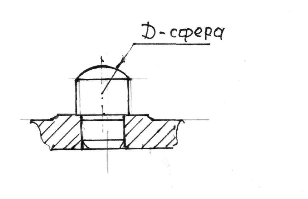 the above pin is used to install not big parts with treated surfaces.
WITH spherical surface
Fitting dimensions are the same.
Fitting dimensions are the same. These pins are used to install small and narrow details with notched heads
Pins with notched heads are used to install the workpiece on raw surfaces.
Round pins ensure the correct position of the machined surfaces relative to the cutting tool, even with uneven mounting surfaces.
Pin Disadvantages:
1. The workpiece may be damaged by high clamping forces. Clamping should be carried out only on supports or strictly between two
2. The possibility of upsetting the workpiece due to the presence of contact defects in
points of contact between the supports and the mounting surface.
Limiting diameters of standard pins d = 3 -24 mm, head diameter
D = 5 40mm, low head height 1 = 2-20mm, high head 1 = 5-40mm, overall
length of pins with low heads L = 6-50mm, with high heads L = 9-70mm.
The pins in the body of the device are installed according to the qualification I v 6.
The bearing pads in the housing for the pin heads should protrude slightly and be processed at the same time, which ensures that the pins are in the same plane. Pins with a flat head after they are pressed in are also ground at the same time, and therefore these pins in size 1 leave an allowance of 0.2-0.3 mm for grinding after assembly.
With intensive use of the fixture, when the pins wear out quickly, a hardened steel bushing is pressed into the housing hole.
The ends of the bushings are simultaneously ground to provide the necessary flatness, and the height £ of the pin heads is performed with a deviation in h 6 or h 5, thus ensuring the interchangeability of the pins in which
eliminates the need to grind their mounting surfaces during assembly and reduces the time to repair the fixture. In the holes of the bushings, the pins are installed according to the landings or
Support plates To install large parts, support is used. In mechanical engineering, two types of base plates are used.
1) without grooves,
2)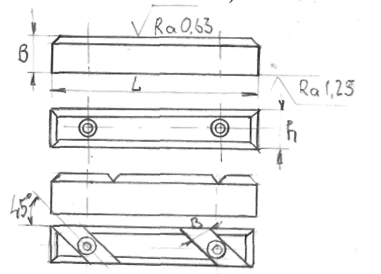 with oblique grooves.
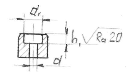
Dimensions of standard plates: width B = 12-35mm; length L = 40-210mm; heightH=8-25mm; h=4-13mm; h 1 \u003d 0.8-3mm, b \u003d 9-22mm;
d= 6-13mm; d 1 \u003d 8.5-20mm.
The plates are fixed with two or three screws; limit screw sizes from M6 to M12mm.
Plates without grooves are mounted on the vertical walls of the housing. When installed on horizontal walls, chips may enter the screw hole, and hence the installation error.
Plates with oblique grooves are installed on the horizontal surfaces of fixtures. With such a design of the plates, the chips shift when the moving part is installed, easily falls into the recesses (oblique grooves) of the plates and does not disturb the contact of the workpiece with the plate.
The plates, like the pins, are fixed on the protruding platforms of the body; if there are several platforms in the same plane, they are processed together.
The number of supports and their location are selected in accordance with the basing schemes. In all cases, when designing fixtures, it is necessary to provide conditions for easy removal of chips from mounting surfaces.
Auxiliary supports. These supports are used in addition to the main ones, when it is necessary to increase the rigidity and stability of the workpiece to be installed. The structures of auxiliary supports and their parts have been normalized. Auxiliary support
brought into contact with the workpiece after its installation on the main
supports and then fixed.
When mechanizing and automating fixtures, auxiliary supports are controlled using a pneumatic or hydraulic drive. In some cases, supports and clamps are sequentially triggered from one drive.
Jack - adjustable support
Screw jack with hole These jacks are used when processing parts with a hole
to exit 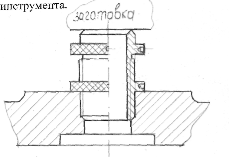
Self-aligning supports
Supports for mounting parts external and cylindrical
surfaces
1.Setting pins
Mounting fingers are used when installing workpieces on basic cylindrical holes. In practice, two cases of installations are most widely used: a) centering and turning the workpiece along two holes; b) centering on one hole and turning along the base plane.
Structurally, the fingers are divided:
fingers adjusting cylindrical constants;
adjusting fingers cut permanent;
fingers adjusting cylindrical replaceable;
fingers adjusting cut off replaceable.
Depending on the diameter of the mounting surface, three modifications of the fingers are made.
Cylindrical
2) diameter over 10mm.
3)Diameter over 20mm
1 ) diameter up to 10mm.
Interchangeable locating pins
Permanent fingers are pressed into the body of the device by square
H1 cast - and the diameters of their mounting surfaces are performed with a deviation
moves on h6 or f9.
Replaceable fingers are used for intensive use of fixtures, when mounting surfaces wear out quickly.
TTP
The fingers are mounted in the bushing hole according to the quality -, diameters
sq.
mounting surfaces are also made with h6 or f9 deviations. When installing heavy parts, when the fixed fingers interfere with the loading of the fixture, the fingers are made retractable
Scheme of combination of fingers with base plates
End and hole installation example
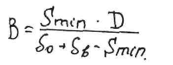
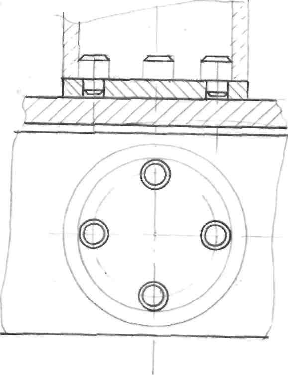
An example of installation along the end and two fingers, one cylindrical, and the second cut.Setting the workpiece on two cylindrical holes with a parallelaxes and on a plane perpendicular to them.
This scheme is used when processing workpieces of small and medium sizes such as cases, plates, frames and crankcases. .
Compared with the six-point setting, this scheme provides greater accessibility of the cutting tool to the workpiece being processed from different sides. The workpiece is secured by applying a clamping force perpendicular to its reference plane. This stability scheme is suitable only for workpieces whose base plane dimensions are greater than or comparable to their height.
Usually two fingers are used, because. a larger number does not increase the accuracy of the installation of the part, and the manufacture of the device becomes more complicated.
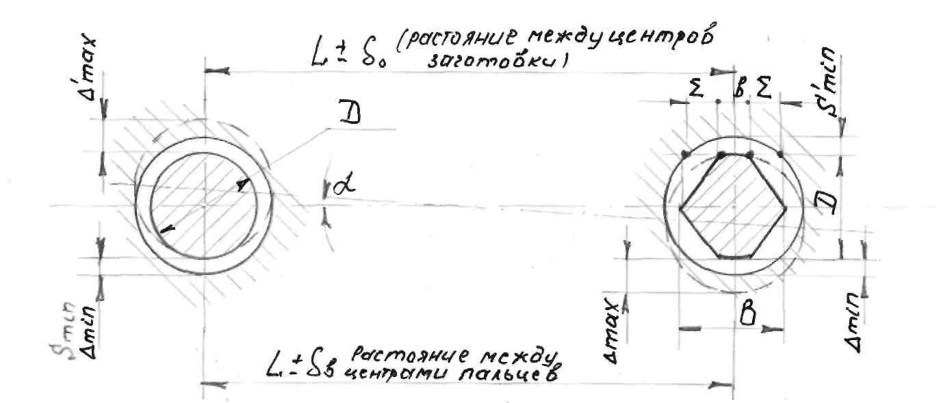
The possibility of misalignment of parts at an angle creates a basing error E, which affects the dimensional accuracy in the manufacture of the part.

Sheared parade grounds make it easier to wrap around the part, tk. the resulting additional clearance compensates for the error in the manufacture of dimension L.
B is the width of the guide band on the cut finger.
where: Smin is the gap at the interface between the cylindrical pin and the workpiece hole;
Smin is the minimum gap in the mating of the cut finger and the hole in the workpiece;
Tolerance for the center distance of the base holes; tolerance for the center distance of the mounting pins.
|
>■ | |||||
Locating a part on a hole large diameter via
fingers.
In group devices, the fingers can be rearranged to other diameters.
Tapered locating pins
1. Self-aligning fingers. They are used when basing with a conical hole or along untreated cylindrical ones.
2. Retractable
Installing the workpiece on the center sockets
When processing shafts and some other parts based on center sockets (conical chamfers), centers with an angle of 60 are used as setting elements.
Installation on a hard center.
Installing with a bevel on the cut center.
Special center with three narrow ribbons, for a rough base.
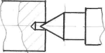
Design leader center, which transmits the torque from the indentation of the corrugations into the surface of the conical chamfer. This center provides the torque needed for finishing, but spoils the surface of the base chamfer.
The design of the driving center where the moment is transmitted through corrugations pressed into the end plane of the workpiece.
Corrugations pos. 1 are made on three sections of the self-aligning washer pos.2. Center pos. 3 of the floating structure is mounted in the intermediate sleeve pos. 4. The center is made of steel 45, U6A, U8A and is subjected to heat treatment to a hardness of HRC 55-60. The wear resistance of the centers can be increased by hardfacing. Preservation of the correct shape of the rear center socket during turning is ensured by the use of rotating centers.
Rigid mandrels
With the development of the accuracy and speed of machines, the requirements for the concentricity of the surfaces of parts are increasing. In many cases, the allowable misalignment of the surfaces is less than 0.01 mm. This accuracy is achieved by using centering fixtures.
Consider some of them, the so-called rigid mandrels.
1 .Tapered mandrels- are used to obtain high concentricity of the treated surfaces when performing finishing operations.
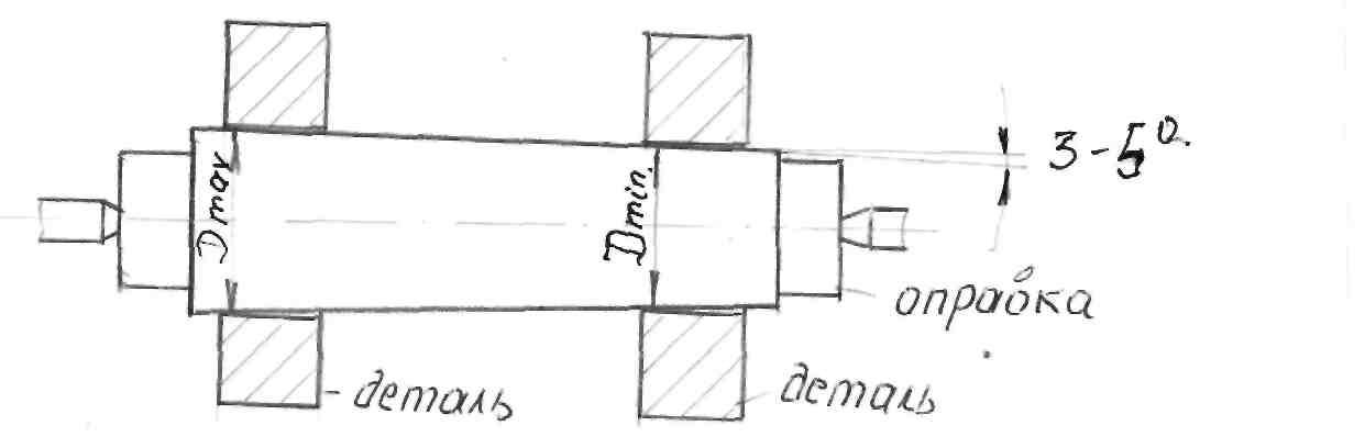
The taper of such mandrels.
3 2000 4000
The part is fixed with light blows of the butt against a wooden lining. The hole in the workpiece is made according to the quality H6 - H7. As a result of the wedging action, the workpiece is firmly kept from turning during processing; centering accuracy 0.005 - 0.01 mm.
The disadvantages of the mandrel include the uncertainty of the position of the workpiece, which excludes the possibility of work on setting.
The working surface of the mandrel is made according to the quality Is6. Mandrels of this type are used in the conditions of single and small-scale production.
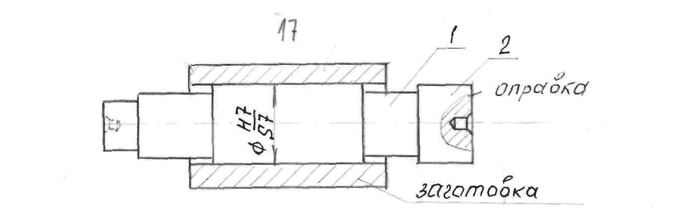
Here is a mandrel on which the workpiece is mounted with an interference fit. Using thrust washer rings when locking, the workpiece is precisely oriented along the length of the mandrel. If you make an annular groove pos.1 on the mandrel, then you can cut both ends of the workpiece. The neck, position 2, is a guide, it serves for free fitting of the workpiece by hand, the centering accuracy on a current mandrel is 0.005 - 0.01 mm.
On such a mandrel, the workpiece is planted with a gap. The position of the workpiece along the length is determined by the collar of the mandrel; its turning is prevented by tightening the nut or a key (if there is a keyway on the workpiece). For these mandrels, the base surfaces of the workpiece are recommended to be processed according to the H7 grade. The centering accuracy depends on the gap and usually does not exceed 0.02-0.03 mm.
The material of the mandrels is steel 20X, with carburizing to a depth of 1.2-1.5mm and Hardening HRc 55-60 units.
The working surface of the necks is ground to Re 0.65 cleanliness. The center sockets are chamfered or underlined to protect against accidental damage. To transmit the moment at the end of the mandrel, a square, flats or a driving pin are provided.
Mandrels with a diameter of more than 80 mm are made hollow to facilitate.
Prisms
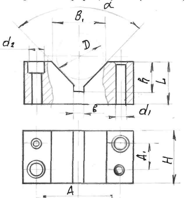
A prism in fixtures is usually called an installation part with a working surface in the form of a groove with an angle a equal to 60,90, or 120, intended primarily for processing surfaces that are located in a certain way relative to the installation cylindrical surface of the part.
The following types of prisms are used in machine tools:
wide - for installing parts with machined surfaces;
narrow - when installing parts on a rough base, as well as suspending stepped shafts.
Large products are mounted on cast iron or welded prisms with replaceable steel plates on inclined surfaces
3. with pins on the mounting surface that have an irregular geometric shape.
According to the degree of mobility of the prism are divided:
adjustable;
self-aligning.
The working surfaces and base of the prism are polished. In prefabricated structures with two or more prisms used to install one part, all prisms are ground together.
Prisms during assembly must be accurately installed in a given position. Therefore, in addition to the fixing screws, two control pins are provided, which fit exactly, without play, both in the holes of the prism and in the holes of the housing on which they are installed.
Prisms are made of steel 20X7 with carburizing to a depth of 0.8-0.9 mm with hardening of the working surface to a hardness of HRC 55-60 units. Prisms of large sizes are made of gray cast iron with hardened steel cheeks screwed on.
Devices that coordinate position tool
When performing individual machining operations (drilling, countersinking, boring), the rigidity of the cutting tool is insufficient. Guide parts are used to eliminate elastic pressing of the tool relative to the workpiece. They must be sufficiently accurate, wear-resistant and, under certain conditions, replaceable. These parts include jig bushings for drilling and boring fixtures.
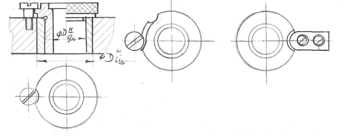
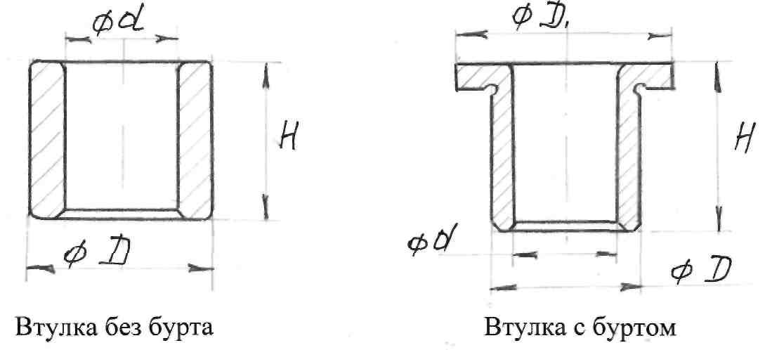
Design and dimensions bushings for drilling are standardized Permanent bushings are manufactured in accordance with GOST 18429-73 without collar, in accordance with GOST 18430-73 with collar, in accordance with GOST 18431-73 replaceable, in accordance with GOST 18432-73 quick-change, in accordance with GOST 18434 intermediate bushings, in accordance with GOST 18434-73 intermediate bushings with shoulder, according to GOST 12464-67 threaded bushings.
The use of conductor bushings eliminates the marking operation, reduces the axis drift and the breakdown of the machined holes. Hole diameter accuracy is increased by an average of 50% compared to machining without drill bushings.
For the manufacture of bushings when drilling with a diameter of up to 9 mm, 9XC steels are used, up to a diameter of 17 mm, U10 steel with a hardness of up to 60 HRC units.
Permanent bushings are installed in the body or plate according to Is6 quality or h6 quality.
Approximate service life of jig bushings 10,000 - 15,000 drills. The average wear rate of conductor bushings when drilling holes with a diameter of 10-20 mm per 10 meters of the path is 3-5 microns when processing medium-hard gray cast iron, 4-6 microns for steel 40, and 1-2 microns for aluminum and its alloys.
Replaceable bushings are placed in permanent ones according to the g6 quality and are fixed with a screw or a bar. When the bushing is worn, it is replaced at the workplace.
The presence of a through recess on the shoulder of the sleeve next to the recess for the head of the fastening screw allows the sleeve to be removed without unscrewing the fastening screw. This is achieved by turning the sleeve to such a position that the through notch is against the head of the fixing screw.
The distance from the surface of the workpiece to be machined to the end of the sleeve, depending on the material being machined, is from 1/3 of the diameter of the drill for machining cast iron and other brittle materials to 1 diameter of the drill for machining steel.
Special drill bushings
They are used in the processing of holes in workpieces of complex configuration and hard-to-reach places, as well as for closely spaced holes.
Conductor plates
Sometimes drill bushings are placed directly in the cast or welded body of the fixture. This achieves high machining accuracy in such a device, since the accuracy in this case depends on the accuracy of the manufacture of the bushings and on the accuracy of the holes for them. However, in order to simplify and reduce the cost of the manufacturing process of the fixture, it is advisable to make the plate separately from the body and attach it to the body with screws. In this case, in order to ensure the exact position of the plate on the body, in addition to the screws, dowel pins are used. Such plates are called permanent.
Permanent plates sometimes create inconvenience when installing and removing the workpiece. Therefore, hinged (folding) plates are often used instead of permanent plates. At one end of such a plate, a hole is drilled for an axle, relative to which the plate can be rotated into a position that provides easy access to the workpiece to be machined. This axis also serves as a support for con-
inductor plate. At the second end of the plate, a slot is made for a hinged screw, with which the plate is pressed against the mounting elements fixed on the body near the hinged screw. This type of plate is characterized by reduced accuracy due to the presence of a movable joint.
In addition to hinged plates, removable plates are used in production, which do not have a permanent connection with the body of the device, are coordinated with the help of fingers precisely located on the body and are strengthened with quick-acting clamps. Such plates provide higher accuracy compared to folding ones and greater freedom of access to workpieces, but they take a lot of time to remove and install. To eliminate these shortcomings, in large-scale and mass production, such plates are suspended from the machine spindle like the plates of multi-spindle heads and are therefore called suspended.
In mass and large-scale production, devices with lifting jig plates are used, which are similar to suspended ones and differ from them only in that they are not permanently connected to the machine spindle, and vice versa, are constantly connected to the body of the device. Thus, the lifting plate fixture can be used on any machine for both single-spindle and multi-spindle drilling. Typically, lifting plates are characteristic of high-speed rock conductors.
Since bushings are installed in the conductor plates, which serve to guide the cutting tool during operation, and the accuracy of processing depends on the accuracy of this direction, sufficient rigidity must be provided for when designing the plates. The thickness of the plates is determined by the height of the conductor sleeve and is within 15-3 mm. For high bushings on the plate, local thickening is provided. The rigidity of the slab is achieved by means of ribs cast in one with the slab or welded to it.
Calculation of the diameter of the bushing
Coupling of the working part of drills, countersinks and rough reamers is carried out according to the F7 qualification in the shaft system.
Finishing sweeps according to G6 quality in the same system.
The largest limiting diameter of the working part of the cutting tool is taken as the nominal diameter of the interface.
Consider an example:
Reamer 18 +0012 Hole deviations in the shaft system by qualification Gl + + lf 0 5 6
Add to the upper deviation of the tool the upper and lower deviation of the required fit. Then the diameter of the bushing will be equal to H 18JJ;JJJ
The F7 and G7 quality between the bushing hole and the cutting tool is taken to compensate for the expansion of the tool during the cutting process.
To increase the accuracy, it is possible to perform pairing according to the H7 quality, but in this case it is necessary to eliminate the heating of the tool and its jamming in the sleeve.
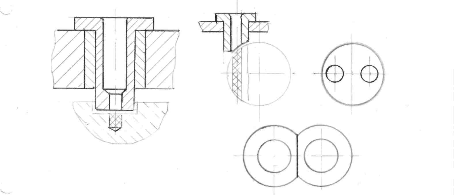
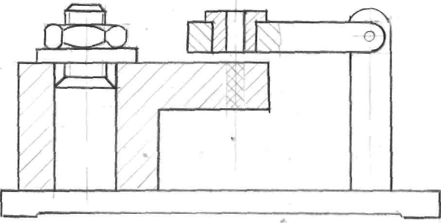
Installations for cutters
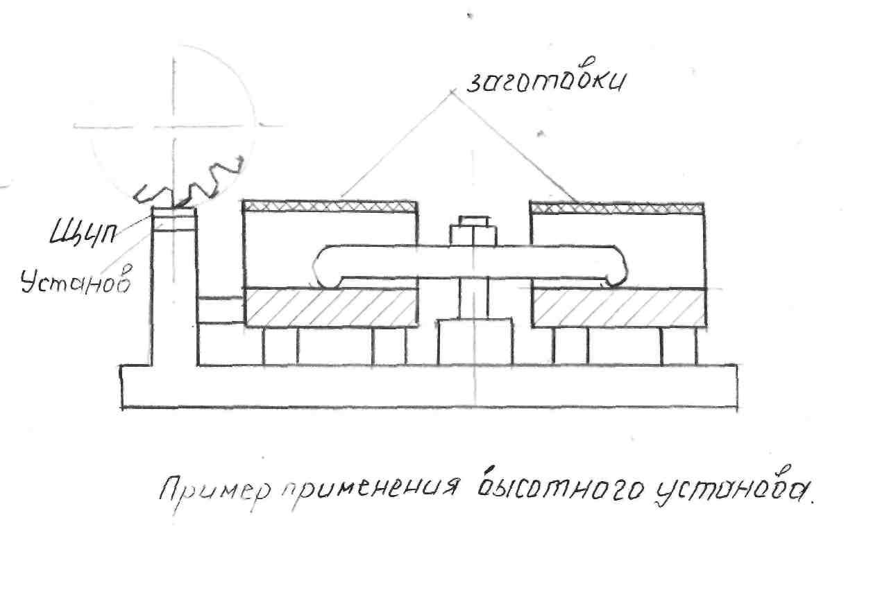
Cutter settings are used to coordinate the relative position of the cutter and the workpiece before starting processing, when processing workpieces on tuned machines to automatically obtain dimensions.
By design, the installations are divided into high-rise, corner and end.
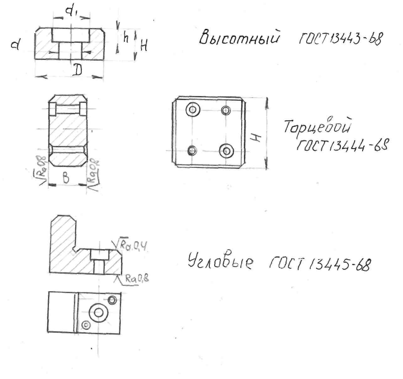
To pass the teeth of the cutter, which, with absolute fine tuning, can touch the end of the installation and damage its surface, the installation is located in the fixture below the surface to be machined by 1-Zmm, so that the cutter during processing is located at the level of the surface to be machined, a probe is laid between the surfaces of the installation and the cutter with a thickness 1 to 5mm
Installation of the cutter according to the installation ensures the accuracy of the corresponding size of the part according to the quality of accuracy.
The material for the manufacture of installations and probes are U7A and 20X steels with heat treatment of the working surface for all installations HRC 55-60 units.
Clamping fixtures
The clamping elements hold the workpiece workpiece from displacement and vibrations arising under the action of cutting forces.
Classification of clamping elements
Clamping elements of fixtures are divided into simple and combined, i.e. consisting of two, three or more interlocked elements.
The simple ones include wedge, screw, eccentric, lever, lever-articulated, etc. - they are called clamps.
Combined mechanisms are usually performed as screw-lever, eccentric-lever, etc. and are called tacks. When simple or combined mechanisms are used in power-driven arrangements
(pneumatic or otherwise) they are called mechanisms - amplifiers. According to the number of driven links, the mechanisms are divided: 1. single-link - clamping the workpiece at one point;
2. two-link - clamping two workpieces or one workpiece at two points;
3. multi-link - clamping one workpiece at many points or several workpieces simultaneously with equal efforts. By degree of automation:
1. manual - working with a screw, wedge and other devices;
2. mechanized, depending on the source of energy are divided into
a) hydraulic
b) pneumatic,
c) pneumohydraulic,
d) mechanohydraulic,
e) electrical,
e) magnetic,
g) electromagnetic,
h) vacuum.
3. automated, controlled from the working bodies of the machine. They are driven by the machine table, caliper, spindle and centrifugal forces of rotating masses.
Example: centrifugal-energy chucks for semi-automatic lathes.
Requirements for clamping devices
They must be reliable in operation, simple in design and easy to maintain; should not cause deformation of the fixed workpieces and damage to their surfaces; fastening and unfastening of workpieces should be carried out with a minimum expenditure of effort and working time, especially when fixing several workpieces in multi-place fixtures, in addition, clamping devices should not move the workpiece during its fastening. Cutting forces should, if possible, not be taken up by the clamping devices. They should be perceived by more rigid installation elements of devices. To improve the accuracy of processing, devices that provide a constant value of clamping forces are preferred.
Let's make a small excursion into theoretical mechanics. What is the coefficient of friction?
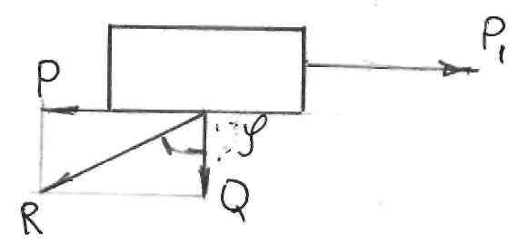
If a body weighing Q moves along a plane with a force P, then the reaction to the force P will be the force P 1 directed in the opposite direction, that is
Friction coefficient
Example: if f = 0.1; Q = 10 kg, then P = 1 kg.
The coefficient of friction varies with surface roughness.
Method for calculating clamping forces
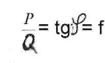
Second case
The cutting force P z and the clamping force Q are directed to one
In this case Q => O
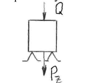
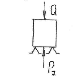
The cutting force P g and the clamping force Q are directed in opposite directions, then Q \u003d k * P z
where k - safety factor k = 1.5 finishing k = 2.5 roughing.
Third case
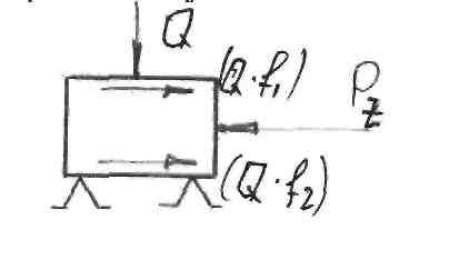
The forces are directed mutually perpendicular. Cutting force P, counteracting the friction force on the support (installation) Qf 2 and the friction force at the clamping point Q * f 1, then Qf 1 + Qf 2 \u003d k * P z
G 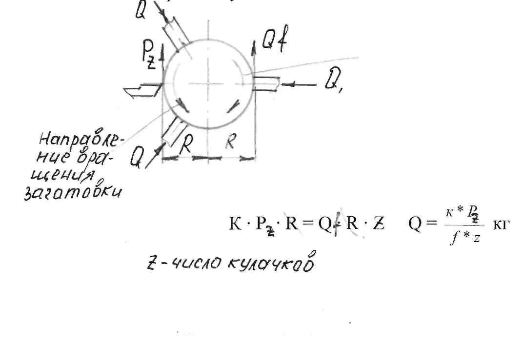 def, and f 2 - coefficients of sliding friction Fourth case
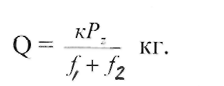
The workpiece is processed in a three-jaw chuck
In this direction, P, tends to move the workpiece relative to the cams.
Calculation of threaded clamping mechanismsFirst case 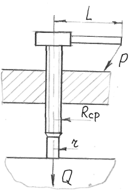
Clamping with a flat head screw From the equilibrium condition 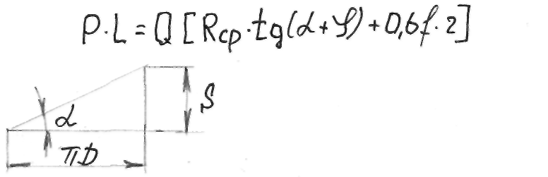
where P is the force on the handle, kg; Q - clamping force of the part, kg; R cp - average thread radius, mm;
R is the radius of the support end;
Helix angle of the thread;
Friction angle in threaded connection ~ 6;  - self-braking condition; f is the coefficient of friction of the bolt on the part;
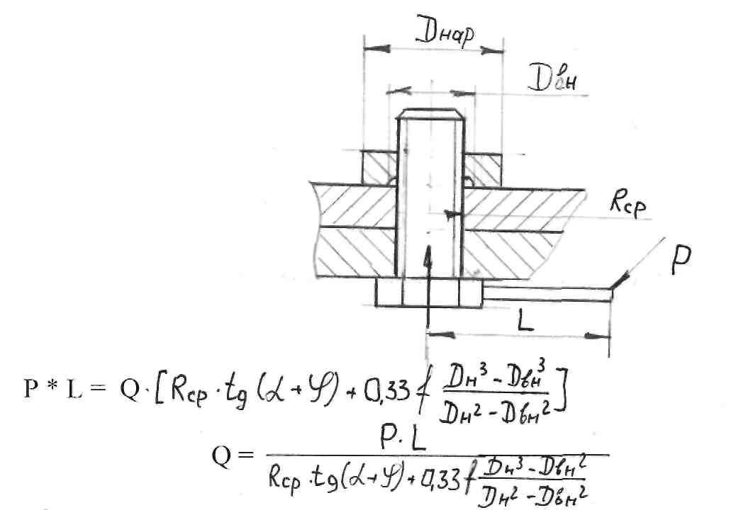
0.6 - coefficient taking into account the friction of the entire surface of the butt. The moment P*L overcomes the moment of the clamping force Q, taking into account the frictional forces in the screw pair and at the end of the bolt.
Second case
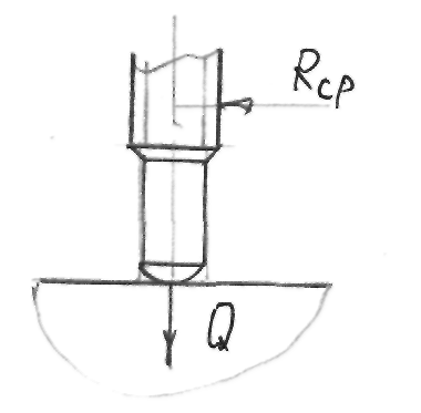 ■Spherical bolt clamping
With increasing angles α and φ the force P increases, because in this case, the direction of the force goes up the inclined plane of the thread.
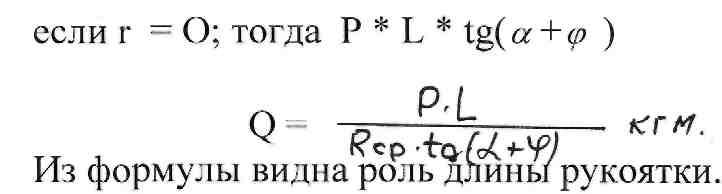
Third case
This clamping method is used when processing bushings or discs on mandrels: lathes, dividing heads or rotary tables on milling machines, slotting machines or other machines, gear hobbing, gear shaping, radial drilling machines, etc. Some information from the guide:
Screw Ml6 with a spherical end with a handle length L = 190 mm and a force P = 8 kg, develops a force Q = 950 kg
Clamping screw M = 24 with a flat end at L = 310mm; P = 15kg; Q=1550mm
Clamp with hexagon nut Ml 6 wrench L = 190mm; P = 10kg; Q = 700kg.
The quality of a product is largely determined by the means of its manufacture. In the engineering industry, the technical characteristics of machine tools and related equipment, which are directly involved in the processing, assembly and assembly of products, are of particular importance. But also a significant role, in terms of ensuring the quality of the result, is played by technological equipment, which is a whole range of additional devices for the main production units.
General information about industrial equipment
The category of technological equipment includes both independent equipment and built-in components, the function of which is reflected in the qualities production process. As for individual units, they can also contribute to the performance of the line indirectly, without being directly related to its capacities. Now it is worth considering what functions the technological equipment and tooling performs as part of the production complex. Its main tasks are to maintain the standard quality of manufactured products, increase production volumes, minimize and facilitate the work of maintenance personnel, etc. These goals are achieved through more efficient preparatory operations using tooling elements, expanding the technological capabilities of machine tools, and reducing processing time. workpieces and through other improvements in the manufacturing process.
Equipment types
The basic division of technological equipment is carried out according to the purpose. In particular, there are control, assembly, machine, fastening and moving elements of equipment equipment. Control equipment serves as an auxiliary component at the stage of auditing the manufactured product for compliance with standards. Assembly fixtures increase the efficiency of assembling finished elements into a single structure, device or complex. The most common machine tool equipment, the presence of which affects the improvement of certain characteristics of the manufactured product - for example, strength, wear resistance or durability of the bearing. Additional fixtures, in turn, improve the technique of fixing the same workpieces during processing or moving within the production site. Accordingly, the moving equipment is an element of the logistics infrastructure and is responsible for the stability and clarity of the movement of products along the same conveyor line.
Tooling Automation
Previously, tooling functions were assigned mainly to technical means intended for manual handling. Then more efficient and productive mechanized counterparts appeared. On the present stage With the development of technological processes, tooling is increasingly endowed with automation functions. It is important to note that the driving source of automation is the main equipment, which, according to the same principle, controls its main nodes. At the same time, technological equipment can work according to combined model and in semi-automatic mode. In such cases, a partially implemented principle of mechanized control is also provided. For this, hydraulic or pneumatic drives are used. One way or another, but almost all modern enterprises are actively switching or have already switched to the use of the concept of automated control.
Production of technological equipment
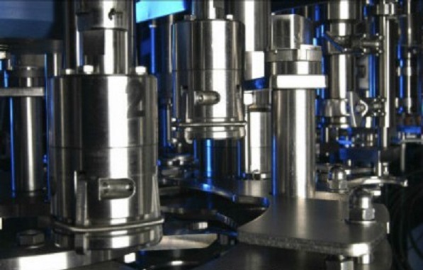 Usually technological process production of tooling elements is based on the use of special strains and molds, which allow serial production of products. Again, to work with non-standard fixtures, the form itself can be developed separately with specific parameters defined in the project. Of course, shaping production technological equipment does not end. This can be followed by the stages of milling, turning and heat treatment, allowing to bring the workpiece to the required operational state. In Russia, many enterprises are engaged in the manufacture of such equipment. For example, the technological equipment plant in Yaroslavl (YaZTO) is engaged in the production of combined, shaping and separating dies, on which it also manufactures large-sized products. Also, the Moscow company Elton, the Belgorod enterprise Ritm and many other plants, one way or another connected with metalworking, are working in this direction.
Conclusion
Often, work on the introduction of equipment into the production facilities cost serious amounts. And in itself, high-quality technological equipment with automation elements can account for almost half of the cost of all equipment at the enterprise. But practice shows that the competent use of auxiliary means is fully justified. In addition, in factories with outdated equipment, the use of modern fixtures is the only way improving the quality of products. - this is a high-quality and proven products of well-known world. It is very important that we cooperate with suppliers for a long time, therefore we offer only with a guarantee - wholesale and at the lowest possible prices. The equipment for lathes is presented in - chucks, rotating centers, racks and gears, cams, tool holders.
More details can be found by calling +7 8482 999-111 or send or e-mail[email protected] site


How to understand: will the kitten be fluffy?
What kind of light alcohol can be drunk for pregnant women: the consequences of drinking
Why do the legs swell in the ankles and ankles of the feet in pregnant women: causes and methods of treatment
The wedding of Prince Harry and Meghan Markle: scandalous and secret details of the marriage (photo) The future marriage of Prince Harry year NTV
How to close white plums for the winter