Section 23. Cam chucks. Three-jaw chuck.
On the turret machines apply two-cam ammo, three-cam cartridges and four-jaw cartridges.
In d double-jaw self-centering chucks they fix a variety of shaped castings and forgings, and often they make special cams designed to fix only one part.
Undercuts are reductions in the diameter machined on the center of workpieces to lighten the piece or to reduce the area of the part for special reasons, such as to hold an O-ring. Some tools, such as drills and reamers, require a reduction in diameter at the ends of the flutes to allow clearance or runout of the cutter or grinding wheel. Reducing the diameter of a shaft or workpiece in the center with fillet shoulders at each end can be done with a round knife.
This tool bit may or may not have a side rail angle, depending on how much work is required. machining. The tool hopper without any side rail is best for machining in any direction. Undercutting is done by feeding the tool chisel into the workpiece while moving the carriage slightly back and forth. This prevents planing and chatter on the work surface.
V three-jaw self-centering chucks fasten round and hexagonal parts or round bars of large diameters.
V four-jaw self-centering chucks bars of square section are clamped, and in simple cartridges with individual adjustment of cams - parts of a rectangular profile and asymmetrical shape.
The shape of the tool and the depth to which it is fed into the job determine the shape and size of the groove. Square and round grooves are often cut on the job to provide room for the tool to run out during subsequent machining operations such as grooving or knurling. These grooves also provide clearance for the assembly of various parts. The grooving tool is a type of forming tool. It shreds without side or rear rakes and is set to work at a central height with minimal overhang.
The side and end angles of the relief, as a rule, are somewhat smaller than for turning tools. To cut a circular groove of a certain radius on a cylindrical surface, the bit of the tool must be grounded to match the correct radius. This method reduces the tool bit and work contact area, thereby reducing chatter, sternness, and tearing. Since the cutting surface of the tool chisel is generally wide, the cutting speed must be slower than for conventional turning.
Cam chucks are made with manual and mechanized clamps.
Rice. 42.
The most common self-centering three-jaw chuck(Fig. 42). Cams 1, 2, 3 move simultaneously with the help of disk 4 with an Archimedean spiral. Cams enter the coils of this spiral with the lower protrusions. On the reverse side a disk is cut with a bevel wheel, to which three bevel gears 5 are connected. When one of them is turned with a key, the bevel wheel of the disk 4 also turns and, by means of a spiral, moves along the grooves of the cartridge body simultaneously and evenly all three cams; depending on the rotation in one direction or another, the cams approach or move away from the center, respectively clamping or releasing the part. The cams are usually made in three stages; they are hardened to increase wear resistance.
A good guideline is to use half the speed recommended for a normal turn. Groove depth or undercut diameter can be checked with external calipers or with two wires and an external micrometer. When using a micrometer and two wires, the micrometer reading is equal to the measured groove diameter plus two wire diameters.
To calculate wire measurement, use the following formula. The most common device for turning centers is the three-jaw chuck. Setup people remove and replace top rigs during each setup, and this task can be relatively easy if quick change chucks are used. However, the vast majority of tri-shot chucks used in turning centers are not quick release chucks; therefore, the installation and replacement of the jaws will take much longer.
According to their purpose, cams are distinguished for internal and outdoor securing workpieces. With internal fixing, the workpiece must have a hole that makes it possible to install it on the cams.
Power-driven chucks can be either traction or built-in.
Drawbar chucks have clamping elements connected by solid or hollow rods to a pneumatic, hydraulic or some other drive. The designs of such cartridges are different, their principle of operation when clamping a part is united.
Most tricuspid cartridges use two pan head screws to clamp each jaw to the main jaw of the cartridge. Thus, only six screws are required for three jaws. The magic jaws on the chuck have small teeth that match the gears on each top of the tool jaw. These serrations are so small that it can be difficult to place each jaw in the same serration of their magical jaw.
It is also important that the jaws be set so that they clamp near the middle of the chuck stroke, and of course the jaws must be set in those teeth that allow the jaws to clamp the workpiece. This can be a difficult task, especially for beginners. If the jaws are not set properly, the entire task of fixing the jaws must be completed. Because the prongs are so small, the installer won't know something is wrong until all three jaws are in place.
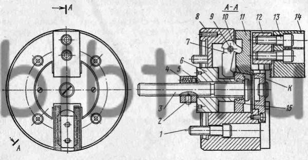
Rice. 43.
On fig. 43 shows the design of a two-jaw lever chuck with interchangeable jaws 14, the preliminary installation of which along the part relative to the axis of rotation is carried out by crackers 12 and screws 13 along the grooves in the sliders 11. The movement of the sliders 11 to the center of the cartridge is carried out by levers 10, which, supported by surfaces 7, rotate around the axis 9 in the body 8 when the stop 15 is moved together with the rod 3. The cams 14 are spread by the conical surface of the stop 15 during the reverse movement of the rod 3 together with the guide sleeve 6 connected by parts 2, 4 and 5. The chuck is attached to the machine with screws 1.
After all, people with tuning can approximate the position of each jaw well so that it clamps the appropriate diameter. However, this skill comes at a cost of trial and error. Mounting sponges can be very frustrating for entry level people when they are trying to figure it out. If you see your people struggling with the task of setting the jaw, you must do something to help them.
While the following method may seem complicated, this is one way to get all three jaws into the correct teeth on the first try. However, this requires a little work. For example, if you have a 25" travel chuck, you are going to mount the jaws with the chuck in the closed position. When installing clamping fixtures that will clamp external diameter, each jaw should be placed in the drive jaw so that its surface in contact with the workpiece is 25 inches less than the diameter that the jaws will press against.

Rice. 44. Chuck section with built-in pneumatic drive
Cartridges with a built-in pneumatic drive (Fig. 44) have a built-in cylinder 6 with a piston 5. The cartridge is attached to the flange 1. The rubber ring 9 softens the blows of the piston against the flange 4. Rings 8 and 10 provide tightness. Sliders 3 with clamping cams have protrusions that enter the grooves of the piston 5. The angle of the grooves is 40 ° 30 ", which provides conditions for self-braking. When air is supplied through channels 2 and 3 into the left or right cavity of the cylinder, the sliders 7 unclamp or clamp blanks.
This will allow you to complete half of the movement of the jaw. When the jaws are actually clamped on the workpiece, they will be in contact with the workpiece in the middle of the chuck's stroke. For soft jaws, you also have to allow for boredom. For an external clamp, subtract the amount of material you are removing from the jaw from the diameter you just determined. For example, to clamp to a 0" diameter with soft jaws, where approximately 1" of material can be removed from each jaw, the mounting diameter would be 55".
Once you have determined the diameter at which each jaw's current clamping surface should be set, you can make a long boring point for that diameter. Then bring the tip of the boring bar close to the face of the chuck. Use the tip of the boring bar to determine which gear should be installed in each jaw. Repeat this procedure for each jaw. When you're done, each jaw will be in the same serration. With hard jaws, the chuck will be in the middle of the stroke when the workpiece is clamped.
Three-jaw self-centering chucks with manual drive and centers have received the greatest use for fixing workpieces during processing on lathes. The main tool for turning on a lathe is a cutter, which is fixed directly in the tool holder of the machine with the help of spacers that allow you to set the cutter so that its top is exactly on the center line.
However, if you install soft jaws, they must be processed. When you are done with them, they will clamp the part in the middle of the chuck stroke. The same technique can be applied to the inner clamps, but you may need to calculate the diameter a bit. If you are still setting the jaws towards the center of the spindle, you will still subtract the travel of the jaw from the diameter of the workpiece to determine the diameter of the chuck. Therefore, for rigid jaws, the calculation is exactly the same as for the external clamp.
However, with soft jaws, you must add twice the amount of material you will be removing from each jaw to the diameter just calculated. This lathe is only for soft materials such as aluminium, plastic and wood, materials that are harder can damage the engine. This mini lathe is specially designed for working with small pieces of soft metals or wood. In the description of the article you can find measures and specifications that allow you to work with the lathe, we also add a video in the photos section where you can watch the work. We remain attentive to your doubts and comments. . This page prints best in widescreen format.
Self-centering three-jaw chuck(Fig. 6.2) consists of a housing 6 with grooves in which the cams 1,2, 3 move. The movement of the cams from the periphery to the center of the cartridge occurs with the help of a spiral cut made on the disk 4. The disk is driven into rotational motion by means of special key installed in the square hole of the bevel gear 5. The bevel gear J is engaged with the disk 4, on which the teeth are cut. Cams are made three-stage, which allows you to fix the workpiece based on inner diameter different size. To increase the wear resistance of the cams, they are hardened.
A lathe is a machine used primarily for shaping metal parts, causing the workpiece to be machined and turning the lathe, while in the work causing the cutting action, a small tool develops. Designed to reduce stock of cylindrical metal, the basic lathe has been further developed for the production of threaded threads, mechanical work, drills, grooved surfaces and crankshafts. Modern lathes offer a variety of rotation speeds and the means to manually and automatically move the cutting tool onto the workpiece.
Centers (Fig. 6.3), depending on the shape and size of the workpieces being processed, have different shape and sizes. The angle at the top of the working part 1 of the center, as a rule, is 60°. The tail part 2 of the center is made with a Morse taper. To remove the center from the hole of the machine spindle or the tailstock quill, the support part 3 is used, the diameter of which is smaller than the diameter of the tail part of the cone, which allows you to remove the center without damaging its conical part.
Operators and maintenance personnel must be thoroughly familiar with the winch and its repair and fabrication operations. Lathes can be divided into three types to make them easier to identify: parallel lathe, rotary lathe, lathes and special purpose. Some smaller jars and semi-finished products. Large lathes are mounted on the ground and may require special transport if they need to be moved. Field storage and general Maintenance use a lathe that can be adapted to many operations and is not too large to move from one workplace to another.
The design of the center is selected depending on the design of the workpiece and the nature of the processing being performed.
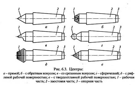
When processing workpieces of small diameter (up to 4 mm), it is difficult to make a center hole in them, therefore the end part of such a workpiece is processed at an angle of 60 °, and its fastening is carried out using a center with reverse cone(Fig. 6.3, b). If during processing it is necessary to cut the end of the workpiece fixed in the centers, then a center with a cut cone is used (Fig. 6.3, c), which is installed only in the tailstock quill. When the axis of the workpiece being processed does not coincide with the axis of the spindle, a spherical center is used to fix it (Fig. 6.3, d). A center with a corrugated working surface (Fig. 6.3, e) is used when processing workpieces with a large center hole without a driver chuck. Due to the fact that during processing large friction forces arise in the centers, hard alloy is used to increase the durability of the centers for their working part (Fig. 6.3, e); such centers are installed in the tailstock quill. Along with solid centers, rotating centers are widely used (Fig. 6.4). Such a center consists of a body 4 with a tapered shank, in which two ball bearings 3 and 5 and one roller bearing 2 are installed. The rotating center 1 is mounted on the bearings.
A power winch is ideal for this purpose. A trained operator can achieve more processing jobs with lathe than with any other machine. Turret lathes and special purpose lathes are often used in manufacturing or work shops for mass production or specialized parts, whereas main engine lathes are typically used for all kinds of turning work. Another reference to winches in this chapter will be from some power winches.
The size of the lathe is determined by most of the actions that can be machined. Before machining a workpiece, the measurements should be considered as follows: the diameter of the workpiece on the bed and the length between turning centers. Slight differences in various mechanical lathes make it easy to group them into three categories: light lathe, precision lathe tool, and sharpening lathes, which is also known as lathe extension type. These categories are shown in Figure 2.
To transfer the rotational movement from the spindle to the workpiece to be processed, chucks and clamps are also used.

Driver chucks
Driver chucks(Fig. 6.5) are used when processing workpieces 5 in centers 4 and 6. Movement is transmitted driver chuck 7 through a leash pin 2 and a collar 3 fixed to the workpiece with a screw.
Light bench lathes are usually small lathes with a swing of 10 inches or less, mounted on a bench or table. These lathes can do most of the machining but can be limited due to the size of the material that can be turned. Precision lathes are also known as standard lathes and are used for all turning operations such as turning, drilling, drilling, milling, threading, spinning, knurling and forming. radius and can be adapted for special milling operations with the appropriate accessory.
Clamp(Fig. 6.6) is put on the workpiece processed in the centers and fixed with a screw 1. With a shank 2, the clamp rests against the pin of the driving chuck.
Gaskets are designed for setting the top of the cutter along the line of centers; they are metal plates of various thicknesses with dimensions corresponding to the dimensions of the support surface of the cutter. The inserts are installed in the tool holder under the cutter, while the thickness of the set is selected so that the top of the cutter is on the center line. The position of the tip of the cutter is controlled by the top of the center installed in the tailstock quill. After adjusting the position of the tip of the cutter, it is fixed in the tool holder of the machine along with a set of selected inserts. The set should not contain more than three plates.


How to understand: will the kitten be fluffy?
What kind of light alcohol can be drunk for pregnant women: the consequences of drinking
Why do the legs swell in the ankles and ankles of the feet in pregnant women: causes and methods of treatment
The wedding of Prince Harry and Meghan Markle: scandalous and secret details of the marriage (photo) The future marriage of Prince Harry year NTV
How to close white plums for the winter