For the implementation of the workflow on the machines, devices are provided for clamping parts, tools, individual machine components, which should ensure the constancy of the position of the tool and workpiece during processing.
Requirements for clamping mechanisms. Mechanismsajima they are very diverse, but regardless of their type, the following requirements are imposed on them: reliability (forces arising during processing should not change the initial position of the part; clamping forces must be maintained during the processing process); sufficient rigidity, eliminating the possibility of vibration; accuracy; universality; design simplicity and small overall dimensions. In addition, they are subject to requirements for the concentricity of the clamping of symmetrical parts, regardless of fluctuations in the dimensions of the workpiece, mechanization and automation of the clamping process, etc.
Classification of clamping mechanisms(Table 3.9). When considering devices, Roman numerals denote the rows of the table, and Arabic numerals denote the corresponding column.
According to the principle of closure, mechanisms with geometric (hard) and force closure are distinguished.
In positive locking (scheme 1), the clamping force is created due to deformations of the transmission and clamping links and can change significantly, for example, as a result of a change in the relative position clamping mechanism and details (relative rotation, crushing of contact surfaces, etc.). The fastening of the part 1 is carried out with the relative movement of the clamping elements 2 (most often by means of screw connections, eccentrics, etc.), and in schemes II - IV, the required clamping force depends on the coefficient of friction of the contacting surfaces. In scheme I, the clamping force is transmitted to the tool 1 through three equally spaced pins 2 during axial movement of the ring 3. The workpiece 1 is fixed in the cams 2 and 3 of the vise (diagram II) by rotating the screw 4. The sleeve 1 is clamped in the hole of the part 3 (diagram III ) is carried out with radial movement of the spacer sleeve 2 due to the rotation of the nut 4. The fixing of the part Y on the slide 3 (Scheme IV) occurs with the axial movement of the conical pin 2.
In mechanisms with force closure, the clamping force is created by external devices (spring, hydraulics, etc.), and in this case it practically does not depend on fluctuations in the dimensions of the installed parts 1 (diagram 2).
Power closure of cutter 1 in tool holder 2 (Scheme I), workpiece clamping 1 in jaws 2 of the chuck lathe(Scheme II), fixation of the rotary faceplate 1 (Scheme III) by stop 2 or slide I (Scheme IV) by hydraulic cylinder 2 is carried out using a spring, hydraulics or pneumatics. Fixing the workpiece (Scheme II) in three-jaw chuck is carried out with axial movement of the rod 3 from the pneumatic cylinder (not shown in the diagram) due to its interaction with the wedge-shaped surface of the cam 4.
Mechanisms are distinguished according to the method of transmission of force. direct action(schemes 3) and lever (schemes 4), in which the labor force is increased using lever or wedge mechanisms. Fixing of tool blocks 1 in holders 2 of turrets of turning modules (scheme 3, I) occurs during axial movement of collet 3. Centering of cutting blocks 1 is carried out using a coupling with a triangular profile. The rotation of the workpiece I (Scheme II) on the mandrel 2 is excluded due to the friction forces that arise at the end when the nut 3 is tightened. mounted on a turntable 1, and part - on a fixed base 3) when oil is supplied to the hydraulic cylinder 4. The clamping of the sled I on the frame 2 (diagram IV) is carried out when oil is supplied to the elastic tubes 3 of an elliptical cross section, which, under pressure, tend to acquire a cylindrical shape .
The mandrel 1 is fixed on the spindle 2 (diagram 4, D) by wedges 3 moved by screw 4. The fastening of the bar stock 2 (diagram II) with the help of the collet U occurs when the nut 3 is rotated. The clamping of the faceplate 1 (diagram III) in any angular position occurs due to the deformation of the plates 2 during the axial movement of the hydraulic cylinder 3. The increase in the clamping force of parts such as sledge 1 when using the lever 2 is shown in diagram IV.
According to the nature of the loading, it is possible to distinguish mechanisms during the operation of which transverse forces arise (schemes 5) and self-adjusting ones (schemes b), in which the clamping forces are balanced. In the first case, deformations of the fixed element occur, which can lead to its displacement from the working position (has a negative effect on the positioning accuracy of nodes, etc.). In schemes 5, the grinding wheel 1 (scheme I), the body Y (scheme II), the quill U (scheme III) and the cylindrical guides Y (scheme IV) are fixed using screw mechanisms 2.
In diagram 6, I, the toolholder Y is clamped in spindle 2 by an axial force transmitted from collet 3 to mandrel Y. As a rule, axial force on the collet is created using Belleville springs (not shown in the diagram). The fixing of the cylindrical part 7 on the conical mandrel 3 is carried out with the help of a collet 2 during the axial movement of the mandrel 3 (scheme II). Plunger 1 (Scheme III) is fixed on base 3 with the help of bellows bushing 2 during its axial deformation (flange 4). The carriage (Scheme IV) is fixed on the cylindrical guide 2 by a clamp 1 connected to the carriage.
Depending on the effect used, clamping mechanisms can be distinguished, the functioning of which is based on the elasticity of the material (schemes 7), the mobility of parts of the clamping mechanisms (schemes 8) and other effects (schemes 9). When clamping the tool holder 1 (diagram 7.1) in the spindle 3, the deformation of the collet 2 is used, which occurs during its axial movement. The fixing of a cylindrical workpiece I with a diameter d on a lathe (scheme II) is carried out due to the deformation of the membrane 2 with the cams 3 installed on it. When the trunnion 4 moves in the direction of the arrow and the membrane is deformed, the workpiece is expanded, and when the trunnion is released, it is fixed with force, depending on the stiffness of the membrane. Clamping of cylindrical parts (scheme III), for example, spindle 2, can be carried out when oil is supplied to the annular chamber and thin-walled bushing I is deformed. pressurized oil.
In diagram 8.1, a cylindrical mandrel 1 or a similar part is fixed when the eccentric 2 is rotated. The fastening of part I in a self-centering three-jaw chuck is shown in diagram II. Part 1 is installed in the centers, and the clamp is carried out by three eccentrically placed segments 2, which have a notched working surface. As the torque increases, the clamping force automatically increases. Scheme III shows the clamping mechanism of spindle 1 with the help of hydraulic cylinders 2 and 3 and friction disc 4. Fastening change jaws I in lathe chuck 2 is shown in scheme IV. The cam 1 is based on a triangular profile coupling 3 and is fixed by means of a rod 4 when the lock 5 is moved.
In scheme 9.1, the vacuum formed in the working cavities is used to clamp the mandrel 1. The value of the force can be adjusted by spring 2. An electromagnet or clamping plates, or plates with permanent magnets are often used to fix parts during flat grinding. Diagram II shows magnetic plates with annular poles. The pole plate is divided into north and south poles with the help of non-magnetic material and serves to create a field between the magnet and the workpiece. In scheme III, to clamp the spindle 1, mounted on hydrostatic bearings, an axial bearing 2 is used, in one of the pockets 3 of which the feed is stopped lubricant. The clamping is carried out by oil pressure in the opposite pocket.
Scheme IV shows how the movable unit 1 is fixed with a thin tape 2 installed in the base. With the help of an electromagnet 3, the assembly is fixed in the required position without any influence of the clamping mechanism on the position of the movable assembly (due to the low rigidity of the tape 2 in the transverse direction). This eliminates the influence of the clamping mechanism on the positioning accuracy.
According to the type of drive, clamping devices with mechanical (schemes 10), spring (schemes 11), hydraulic or pneumatic (schemes 12) and electromechanical (schemes 13) drives are distinguished. Mandrel 1 is fixed (diagram 10, I) by evenly spaced screws 2 with a spherical tip. Part 1 (Scheme II) is fixed through the lever system during axial movement of the rod 2. The column 1 of the radial drilling machine (Scheme III) is fixed by the rod 2 when the screw 3 is rotated. collar 4 with cone-shaped surfaces. The tool holder is centered on the slider by a cam clutch 2 with a triangular profile.
Quite often, springs are used for clamping (schemes 11). The replaceable part 1 (scheme I) of the tool block is fixed on the holder 2 of the cutting head of the lathe during axial movement of the rod 3 (under the action of a spring). In this case, the rod 3 with its conical part acts through the inclined pins 4 on the conical groove of the replaceable part of the block. Clamping of blanks 1 (schemes 11,11 Vi 12, II) is carried out through lever 3 using hydraulic cylinder 2, the force in which is developed either by a spring (scheme 11, II) or oil pressure (scheme 12, II). The fixing of the faceplate 1 (scheme 11, III) is carried out due to the deformation of the tuning fork mechanism by the spring 2.
The clamping of the crossbar 1 of the lathe with the help of a spring and a wedge mechanism is shown in Scheme 11, IV. The spring force is transmitted through wedge 2 to rod 3 and lever 4.
Securing parts using hydraulics (pneumatics) is shown in diagrams 12. Mandrel 1 (diagram I) is fixed in spindle 2 when oil is supplied to a closed cylindrical cavity. Fixation of the quill 1 of the tailstock (Scheme III) when it abuts against the part 3 is carried out due to the deformation in the radial direction of the weakened sections 2 of the quill. Part 1 (or satellite) is clamped using hydraulic cylinder 2 and rotary lever 3 (Scheme IV).
Electromechanical drives of clamping mechanisms (diagrams 13) develop large forces and therefore have increased dimensions. They include the engine M and the actuator, made, as a rule, in the form of a screw-nut transmission. In the scheme / fastening tool on milling machine is carried out during the axial movement of the thrust 1, the movement to which is transmitted from the engine M through the planetary gear 2 and the nut 3. In diagram II, the axial movement of the thrust 1 chuck to clamp the workpiece is carried out through a worm and screw gear. In scheme III, shaft 1 is fixed from rotation by an electromagnetic clutch 3 connected to housing 2.
The electromechanical clamping of the crossbar 1 (Scheme IV) of vertical lathes develops exceptionally large forces due to the large gear ratio from the motor M to the clamped element.
On fig. 3.70 shows a variety of tool clamping mechanisms mounted along the spindle axis in machine tools various types. On fig. 3.70, and the fastening of the mandrel 1 in the conical bore of the spindle 2 is carried out from a package of Belleville springs 4. One end of the springs abuts against the end of the spindle, and the other is connected to the rod 5 (not shown). The rod 5 acts through the collet 3 on the shank of the mandrel, securing the tool. The unclamping is performed by a hydraulic cylinder (not shown), which moves the rod 5 with the collet forward, as a result of which the conical shank of the mandrel is released. Most of the clamping mechanisms have a similar scheme.

In the design shown in Fig. 3.70, b, the clamping sleeve 2, connected with the spring-loaded rod 4, transfers the force to the mandrel 1 through the balls 3. In fig. 3.70, in the mandrel 1 interacts through the balls 2 directly with the rod 3. In the collet clamping mechanism (Fig. 3.70, d), the force from the rod 6, petals 3 and 7 of the collet is transmitted to the mandrel 1 through the shank 2 screwed into it. position) occurs due to the interaction of the sleeve 5 with the end of the petals 3 and 7, as well as under the action of the spring 4.
In the considered mechanisms, due to malfunctions in the clamping mechanism (breakage of the spring) or specific cutting conditions that do not exclude the “pickup” of the tool (for example, due to an uncontrolled increase in cutting force), its axial movement and breakage are possible. In addition, to ensure a large clamping force, the Belleville springs must be installed in series, as a result of which a significant part of the force is lost due to the friction of the ends of the springs.
On fig. 3.71 shows the clamping mechanism, in which the disadvantages noted above are excluded. Here, a relatively small force from the spring 1 is transmitted through the conical surfaces of the bushings 2,3,5 and the ball 4 to the rod 6 (lower part). The choice of tilt angles conical surfaces(for example, α ≈ 12°) it is possible to provide a corresponding increase in the force of the spring when it is transferred to the rod 6 (5 - 6 times). At the same time, when an axial force F arises on the “extraction”, due to the fact that the angle a is chosen close to the angle of friction, the coefficient of force transfer from the rod 6 to the spring 1 additionally increases by 10 times or more. Thus, the mechanism forms a lock, and movement of the tool in the axial direction is practically impossible under any influence.
In three-jaw lathe chucks with various cam drive mechanisms, the rocker arm principle is used in fig. 3.72 a. Sleeve 1, screwed to a draw rod (not shown), interacts with rocker arms 2, the axes of which are installed in the cartridge body. The short arms of the levers included in the grooves of the base of the cams 3 move them in the radial direction. Screws 4 clamping jaws (not shown) are fixed on the movable jaws. Three pairs of rails 4 and 5 are located in the body of the wedge-rack chuck, respectively, with a small and large angle of inclination of the teeth, engaging with the teeth of the cams 3 (Fig. 3.72, b). The rails 4 are connected to the bushing 2 and serve for clamping - unclamping the workpiece. The rails 5 are connected to the sleeve 1 and are designed to change the position of the clamping jaws when switching to a different processing diameter. To do this, the rails 4 disengage from the cams, and the rails 5 engage with them, making it possible to move the cams. Both bushings 1 and 2 are driven by hydraulic cylinders.


The cartridge shown in fig. 3.72, c, provides centering of the workpiece with cams (during chucking), as well as self-alignment of the cams on the workpiece (when machining in centers). The center in the cartridge is made floating: with a certain force of pressing the workpiece by the tailstock quill, the Belleville springs are compressed and the center is recessed. Cam base 2 is driven by a wedge mechanism when bushing 1 is moved, connected by a rod to a hydraulic cylinder (not shown in the diagram). In a chuck with rack and pinion cams, the cams are driven by a hydraulic motor (Fig. 3.72, d) mounted at the rear end of the spindle (not shown in the diagram). The rotor 1 of the hydraulic motor (diagram II) is connected to the bushing 2 (diagram I) and to the gear wheel 3. When the hydraulic motor is turned to the right (at an angle φ p), the wedges 4 with helical racks engage r with the thread on the interchangeable jaws 5, causing them to radially movement and clamping of the workpiece. When the hydraulic motor rotor is turned to the left side (at an angle of φ cm), the wedges of the rack are disengaged from the helical cut on the cams, releasing them. After that, the jaws can be reset manually to a given diameter.
In the hydraulic cylinder for clamping parts (cam drive) of lathes, the hydraulic cylinder 3 (Fig. 3.73), which transmits force to the thrust I of the cam drive, is installed on the pulley 2 of the spindle rotation drive. Weights 4 are provided to reduce imbalance. Oil is supplied to the hydraulic cylinder through spool 5.
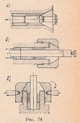
In a three-jaw chuck for fixing crankshafts, crankshaft 1 is installed at centers 6 and clamped by cams 2 using a wedge mechanism 3 during axial movement of pistons 4 associated with sleeve 5 (Fig. 3.74). Fastening and unfastening is carried out by a hydraulic cylinder (not shown).
A self-aligning direct-acting clamp avoids transverse loads on node I due to pliable petals 2 and 3 in the direction of the clamp (Fig. 3.75, a). The clamp shown in Fig. 3.75, b, allows, on the fixed node 3, to significantly increase the force developed by the belleville springs 1 of the mechanism due to the lever 2.
Clamping elements are mechanisms directly used to clamp workpieces, or intermediate links in more complex clamping systems.
The simplest kind universal clamps are that actuate the keys, handles or handwheels mounted on them.
To prevent movement of the clamped workpiece and the formation of dents on it from the screw, as well as to reduce the bending of the screw when pressing on a surface that is not perpendicular to its axis, rocking shoes are placed on the ends of the screws (Fig. 68, α).
Combinations screw devices with levers or wedges are called combination clamps and, a variety of which are screw clamps(Fig. 68, b), The clamping device allows you to move or rotate them so that you can more conveniently install the workpiece in the fixture.
On fig. 69 showing some designs quick release clamps. For small clamping forces, a bayonet device is used (Fig. 69, α), and for significant forces, a plunger device (Fig. 69, b). These devices allow the clamping element to be retracted a long distance from the workpiece; fastening occurs as a result of the rotation of the rod through a certain angle. An example of a clamp with a folding stop is shown in fig. 69, c. Having loosened the nut-handle 2, the stop 3 is retracted, rotating it around the axis. After that, the clamping rod 1 is retracted to the right at a distance h. On fig. 69, d shows a diagram of a high-speed lever-type device. When the handle 4 is turned, the pin 5 slides along the bar 6 with an oblique cut, and the pin 2 slides along the workpiece 1, pressing it against the stops located below. Spherical washer 3 serves as a hinge.

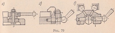
The large time and considerable forces required to clamp the workpieces limit the scope of screw clamps and in most cases make quick-acting clamps preferable. eccentric clamps. On fig. 70 shows disk (α), cylindrical with L-shaped clamp (b) and conical floating (c) clamps.
Eccentrics are round, involute and spiral (according to Archimedes' spiral). In clamping devices, two types of eccentrics are used: round and curved.
Round eccentrics(Fig. 71) are a disk or roller with an axis of rotation shifted by the size of the eccentricity e; the self-braking condition is ensured at a ratio of D/e≥ 4.
The advantage of round eccentrics lies in the ease of their manufacture; the main disadvantage is the inconsistency of the elevation angle α and the clamping forces Q. Curvilinear eccentrics, the working profile of which is performed along the involute or Archimedes' spiral, have a constant angle of elevation α, and, therefore, ensure the constancy of the force Q, when clamping any point of the profile.

wedge mechanism used as an intermediate link in complex clamping systems. It is easy to manufacture, easily placed in the device, allows you to increase and change the direction of the transmitted force. At certain angles, the wedge mechanism has self-braking properties. For a single-sided wedge (Fig. 72, a), when forces are transferred at a right angle, the following dependence can be taken (for ϕ1 = ϕ2 = ϕ3 = ϕ where ϕ1…ϕ3 are friction angles):
P = Qtg (α ± 2ϕ),
where P - axial force; Q - clamping force. Self-braking will take place at α<ϕ1 + ϕ2.
![]()
For a double-beveled wedge (Fig. 72, b) when transferring forces at an angle β> 90, the relationship between P and Q at a constant friction angle (ϕ1 = ϕ2 = ϕ3 = ϕ) is expressed by the following formula:
P = Qsin(α + 2ϕ)/cos(90° + α - β + 2ϕ).
Lever clamps used in combination with other elementary clamps, forming more complex clamping systems. Using the lever, you can change the magnitude and direction of the transmitted force, as well as carry out simultaneous and uniform clamping of the workpiece in two places. On fig. 73 shows the diagrams of the action of forces in one-arm and two-arm straight and curved clamps. The equilibrium equations for these lever mechanisms are as follows; for one shoulder clamp (Fig. 73, α):

direct two-shoulder clamp (Fig. 73, b):

curved clamp (for l1 where p is the angle of friction; ƒ - coefficient of friction. Centering clamping elements are used as mounting elements for the outer or inner surfaces of bodies of revolution: collets, expanding mandrels, clamping sleeves with hydroplastic, and also membrane cartridges. The taper angle of the compression sleeve is made 1° less or greater than the taper angle of the collet. Collets provide installation eccentricity (runout) no more than 0.02 ... 0.05 mm. The base surface of the workpiece should be machined according to the 9th ... 7th grade of accuracy. Expanding mandrels various designs (including designs with the use of hydroplastic) are classified as clamping fixtures. Diaphragm cartridges used for precise centering of workpieces on the outer or inner cylindrical surface. The cartridge (Fig. 75) consists of a round membrane 1 screwed to the faceplate of the machine in the form of a plate with symmetrically located protrusions-cams 2, the number of which is chosen in the range of 6 ... 12. A rod of 4 pneumatic cylinders passes inside the spindle. When the pneumatics are turned on, the membrane flexes, pushing the cams apart. When the rod moves back, the membrane, trying to return to its original position, compresses the workpiece 3 with its cams. rack and pinion clamp(Fig. 76) consists of a rack 3, a gear wheel 5 sitting on a shaft 4, and a handle lever 6. By turning the handle counterclockwise, lower the rack and clamp 2 to fix the workpiece 1. The clamping force Q depends on the value of the force P applied to the handle. The device is equipped with a lock, which, jamming the system, prevents the wheel from turning back. The most common types of locks are: roller lock(Fig. 77, a) consists of a driving ring 3 with a cutout for roller 1, which is in contact with the cut plane of the roller. 2 gears. The driving ring 3 is fastened to the handle of the clamping device. Rotating the handle in the direction of the arrow, the rotation is transmitted to the gear shaft through roller 1*. The roller is wedged between the bore surface of the housing 4 and the cut plane of the roller 2 and prevents reverse rotation. Direct Drive Roller Lock moment from the driver to the roller is shown in fig. 77b. The rotation from the handle through the leash is transmitted directly to the shaft 6 of the wheel. Roller 3 is pressed through pin 4 by a weak spring 5. Since the gaps at the points of contact of the roller with ring 1 and shaft 6 are chosen, the system instantly wedges when the force is removed from handle 2. By turning the handle in the opposite direction, the roller wedges and rotates the shaft clockwise . conical lock(Fig. 77, c) has a conical sleeve 1 and a shaft with a cone 3 and a handle 4. The spiral teeth on the middle neck of the shaft are engaged with the rail 5. The latter is connected to the actuating clamping mechanism. When the angle of inclination of the teeth is 45°, the axial force on the shaft 2 is equal (excluding friction) to the clamping force. * Locks of this type are made with three rollers located at an angle of 120°. Combined clamping devices are a combination of elementary clamps of various types. They are used to increase the clamping force and reduce the dimensions of the device, as well as to create the greatest ease of management. Combined clamping devices can also provide simultaneous clamping of the workpiece in several places. Types of combined clamps are shown in fig. 78. The combination of a curved lever and a screw (Fig. 78, a) allows you to simultaneously fix the workpiece in two places, evenly increasing the clamping forces to a predetermined value. The usual rotary clamp (Fig. 78, b) is a combination of lever and screw clamps. The swing axis of the lever 2 is aligned with the center of the spherical surface of the washer 1, which unloads the pin 3 from bending forces. With a certain lever arm ratio, the clamping force or stroke of the clamping end of the lever can be increased. On fig. 78, d shows a device for fixing a cylindrical workpiece in a prism by means of a cap lever, and in fig. 78, e - scheme of a quick-acting combined clamp (lever and eccentric), which provides lateral and vertical pressing of the workpiece to the fixture supports, since the clamping force is applied at an angle. A similar condition is provided by the device shown in Fig. 78, e. Toggle clamps (fig. 78, g, h, and) are examples of quick-acting clamping devices driven by turning the handle. To prevent self-detachment, the handle is moved through the dead position until it stops 2. The clamping force depends on the deformation of the system and its rigidity. The desired deformation of the system is set by adjusting the pressure screw 1. However, the presence of a tolerance for size H (Fig. 78, g) does not ensure the constancy of the clamping force for all workpieces of a given batch. Combined clamping devices are operated manually or from power units. Clamping mechanisms for multiple fixtures must provide the same clamping force in all positions. The simplest multi-place device is a mandrel, on which a package of blanks “rings, disks” is installed, fixed along the end planes with one nut (serial clamping force transmission scheme). On fig. 79, α shows an example of a clamping device operating on the principle of parallel clamping force distribution. If it is necessary to ensure the concentricity of the base and machined surfaces and prevent deformation of the workpiece, elastic clamping devices are used, where the clamping force is uniformly transferred to the clamping element of the fixture by means of a filler or other intermediate body within the limits of elastic deformations). Conventional springs, rubber or hydroplastic are used as an intermediate body. A parallel action clamping device using hydraulic plastic is shown in fig. 79b. On fig. 79, a device of mixed (parallel-serial) action is shown. On continuous machines (drum-milling, special multi-spindle drilling) workpieces are installed and removed without interrupting the feed movement. If the auxiliary time overlaps with the machine time, then various types of clamping devices can be used to secure the workpieces. In order to mechanize production processes, it is advisable to use clamping devices of automated type(continuous action), driven by the feed mechanism of the machine. On fig. 80, α shows a diagram of a device with a flexible closed element 1 (cable, chain) for fixing cylindrical workpieces 2 on a drum-milling machine when processing end surfaces, and in fig. 80, 6 is a diagram of a device for fixing piston blanks on a multi-spindle horizontal drilling machine. In both devices, operators only install and remove the workpiece, and the clamping of the workpiece occurs automatically. An effective clamping device for holding thin sheet workpieces during their finishing or finishing is a vacuum clamp. The clamping force is determined by the formula: where A is the active area of the cavity of the device, limited by the seal; p= 10 5 Pa - the difference between atmospheric pressure and pressure in the cavity of the device from which air is removed. Electromagnetic clamping devices are used for fixing workpieces made of steel and cast iron with a flat base surface. Clamping devices are usually made in the form of plates and cartridges, in the design of which the dimensions and configuration of the workpiece in plan, its thickness, material and the required holding force are taken as initial data. The holding force of the electromagnetic device largely depends on the thickness of the workpiece; at small thicknesses, not all of the magnetic flux passes through the cross section of the part, and part of the magnetic flux lines is scattered into the surrounding space. Parts processed on electromagnetic plates or cartridges acquire residual magnetic properties - they are demagnetized by passing them through a solenoid powered by alternating current. To reduce the time for installation, alignment and clamping of parts, it is advisable to use special (designed for processing this part) clamping devices. It is especially advisable to use special devices in the manufacture of large batches of identical parts. Since the fixtures must quickly and reliably fix the workpiece, it is preferable to use such clamps when clamping one workpiece in several places is simultaneously achieved. Ha fig. 74 shows a clamping device for a body part, in which the clamping is carried out simultaneously by two clamps 1
and 6
on both sides of the part by tightening one nut 5
. When tightening the nut 5
pin 4
, having a double bevel in the die 7
, through traction 8
affects the bevel of the die 9
and tighten with a nut 2
sticking 1
sitting on a pin 3
. The direction of the clamping force is shown by arrows. When loosening the nut 5
springs placed under the clamps 1
and b, lift them, freeing the part. Single clamping fixtures are used for large parts, while for small parts it is more advisable to use fixtures in which several workpieces can be installed and clamped at the same time. Such devices are called multi-seat. Fastening several workpieces with one clamp reduces the time for fastening and is used when working on multi-place fixtures. On fig. 76 shows a multi-seat device with a pneumatic piston power drive. Compressed air enters through a three-way valve either into the upper cavity of the cylinder, clamping the workpieces (the direction of the clamping force is shown by arrows), or into the lower cavity of the cylinder, releasing the workpieces. In the described device, a cassette method of installing parts is used. Several workpieces, for example five in this case, are placed in the cassette while another batch of the same workpiece is already being processed in the cassette. After processing is completed, the first cassette with milled parts is removed from the device and another cassette with blanks is installed there instead. The cassette method allows you to reduce the time for installing blanks. When choosing the type of clamping devices, the following rules should be followed. When milling against feed and left hand rotation cylindrical cutter the clamping force must be directed as shown in fig. 78, a, and with right rotation - as in fig. 78b. 1. What devices are used when fixing workpieces directly on the machine table? Collets are split spring sleeves, the design variations of which are shown in fig. 74 (α - with a tension tube; 6 - with a spacer tube; in - vertical type). They are made of high-carbon steels, for example, U10A, and heat-treated to a hardness of HRC 58...62 in the clamping and to a hardness of HRC 40...44 in the tail parts. Collet taper angle α = 30…40°. At smaller angles, collet jamming is possible.
 eccentric lock(Fig. 77, d) consists of a wheel shaft 2, on which an eccentric 3 is wedged. The shaft is driven by a ring 1 fastened to the lock handle; the ring rotates in the body bore 4, the axis of which is offset from the shaft axis by a distance e. When the handle is rotated backwards, the transmission to the shaft occurs through the pin 5. In the process of fixing, the ring 1 is wedged between the eccentric and the body.
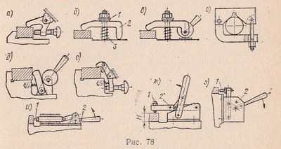

Special clamping devices can have screw, eccentric, pneumatic, hydraulic or pneumohydraulic clamping.Scheme of a single fixture

Multiple fixtures
On fig. 75 is a diagram of a double fixture for clamping two rollers when milling keyways. The clamp is made with a handle 4
with an eccentric that simultaneously presses the clamp 3
and through traction 5
for sticking 1
, thereby pressing both workpieces to the prisms in the body 2
fixtures. The rollers are released by turning the handle 4
reversed. At the same time, the springs 6
pull back the grips 1
and 3
.
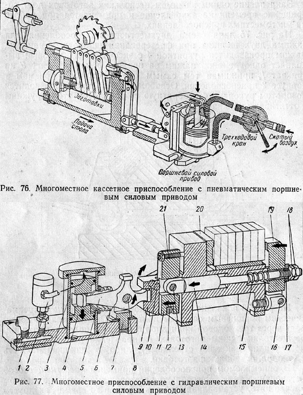
On fig. 77 shows the design of a multi-place clamping device with a hydraulic drive.
Base 1
drive is fixed on the machine table. in a cylinder 3
the piston moves 4
, in the groove of which the lever is installed 5
, rotating around an axis 8
, fixed in the eye 7
. The lever arm ratio of 5 is 3:1. With an oil pressure of 50 kg / cm 2 and piston diameter 55 mm force at the short end of the lever arm 5
reaches 2800 kg. To protect against chips, a cloth casing 6 is put on the lever.
Oil flows through a three-way control valve into the valve 2
and further into the upper cavity of the cylinder 3
. Oil from the opposite cavity of the cylinder through the hole in the base 1
enters the three-way valve and then to the drain.
When the handle of the three-way valve is turned to the clamping position, pressurized oil acts on the piston 4
, transmitting the clamping force through the lever 5
fork lever 9
clamping device that rotates on two axle shafts 10
. Finger 12
, pressed into the lever 9, turns the lever 11
relative to the point of contact of the screw 21
with fixture body. At the same time, the axis 13
lever moves the rod 14
to the left and through the spherical washer 17
and nuts 18
transfers the clamping force to the clamp 19
, rotating around the axis 16
and pressing the workpieces to the fixed jaw 20
. Adjustment of the clamping size is carried out by nuts 18
and screw 21
.
When the handle of the three-way valve is turned to the open position, the lever 11
turns in the opposite direction, moving the thrust 14
to the right. At the same time, the spring 15
removes the stick 19
from blanks.
Recently, pneumohydraulic clamping devices have been used, in which compressed air coming from the factory network with a pressure of 4-6 kg / cm 2 presses on the piston of the hydraulic cylinder, creating an oil pressure of about 40-80 kg / cm 2. Oil with this pressure, using clamping devices, secures the workpieces with great effort.
Increasing the pressure of the working fluid allows, with the same clamping force, to reduce the size of the vise drive.Rules for choosing clamping devices
Clamps must be simple, quick-acting and easily accessible to actuate them, sufficiently rigid and not loosen spontaneously under the action of the cutter, from vibrations of the machine or under the influence of random causes, must not deform the surface of the workpiece and cause its springback. The clamping force in the clamps is opposed by a support and should, if possible, be directed in such a way as to assist in pressing the workpiece against the supporting surfaces during machining. To do this, the clamping fixtures should be installed on the machine table so that the cutting force that occurs during the milling process is perceived by the fixed parts of the fixture, for example, the fixed vice jaw.
On fig. 78 shows the installation diagrams of the clamping device.
When milling with a face mill, depending on the feed direction, the clamping force should be directed, as shown in fig. 78, in or fig. 78, city
With this arrangement of the fixture, a rigid support is opposed to the clamping force and the cutting force helps to press the workpiece against the supporting surface during processing.CONTROL QUESTIONS
2. What is a corner plate (angle) and when is it used?
3. For fixing what workpieces are prisms used?


How to understand: will the kitten be fluffy?
What kind of light alcohol can be drunk for pregnant women: the consequences of drinking
Why do the legs swell in the ankles and ankles of the feet in pregnant women: causes and methods of treatment
The wedding of Prince Harry and Meghan Markle: scandalous and secret details of the marriage (photo) The future marriage of Prince Harry year NTV
How to close white plums for the winter