Full text search:
Home > Abstract >Industry, production
abstract
The course project was completed in accordance with the assignment and contains 4 sheets of A1 format (part drawing, workpiece drawing, fixture drawing (technological equipment), technological adjustments) and an explanatory note consisting of 52 sheets, 4 drawings, 6 tables. 8 sources were used in the work.
Theme of the course project: “Development technological process production of the “Step Shaft” part.
In the process of work, a route-operational technological process was designed, designed in accordance with the ESTD.
Introduction 5
1 Designing the machining process of a part 6
1.1 Service purpose of the part and technical requirements on her 6
1.2 Technological control of the drawing and analysis of manufacturability
designs 7
1.3 Determining the type of production 9
1.4 Justification of the choice and determination of the dimensions of the original
blanks 14
1.5 Designing route technology for part processing 17
1.6 Calculation of machining allowances 19
1.7 Operating technology design 23
1.7.1 Calculating cutting conditions and times 23
1.7.1.1 Designing operation No. 010 "CNC Turning" 23
1.7.1.2 Designing operation No. 020 "Milling" 30
1.7.1.3 Designing operation No. 025 "Bolt-cutting" 37
1.7.2 Machining accuracy calculation 44
1.7.3 Equipment selection 46
2 Design of technological equipment 48
2.1 Selection and justification for installing the part in fixture 48
2.2 Technical description design and working principle
fixtures 48
2.3 Development of a calculation scheme for fastening and calculation of the mechanism
clamp 48
References 51
Annex 52
Introduction
Shafts are very different in terms of service purpose, constructive form, size and material. Despite this, the technologist, when developing the technological process for manufacturing shafts, has to solve many similar tasks, so it is advisable to use standard processes that are created on the basis of the classification.
In general mechanical engineering, there are stepless and stepped shafts, solid and hollow, smooth and splined, gear shafts, as well as combined shafts in various combinations from the above groups. According to the shape of the geometric axis, the shafts can be straight, crankshaft, crank and eccentric (cam).
The most widespread in mechanical engineering, including machine tool building, are various medium-sized stepped shafts, among which smooth shafts predominate. According to ENIMS, over 85% of the total number of standard sizes of stepped shafts in mechanical engineering are shafts with a length of 150-1000 mm.
Shaft journals may have keyways, splines or threads. It is often advantageous to replace threads for securing mating parts against axial movement with grooves for spring rings. This simplifies handling and assembly. Grooves or fillets are made at the transition points of the steps. Fillet processing is more complex; it is therefore preferable, where possible, to provide grooves. Shaft ends are chamfered. Splined shafts can be with through and closed splines, the latter make up about 65% of the total number of sizes. By design, splines can be straight-sided and involute. Currently, straight-sided shafts predominate (approximately 85-90% of the total number of splined shaft sizes used in mechanical engineering), although involute splines have a number of advantages in terms of technology.
Shafts with a ratio of length to diameter less than 15 are classified as rigid; with a ratio of more than 15, the shafts are considered non-rigid.
1. Process design machining details
1.1 Service purpose and technical requirements for the part according to the drawing and operating conditions
Detail - stepped shaft. The material used is steel 30X13 GOST 5632-72. The shaping method is forging. After final processing, the shaft is sent for assembly.
The shaft has five journals, made according to the 6th grade of accuracy with a roughness according to the parameter Ra 1.25 (38js6; 40js6; 45js6; 32.2n6; 32n6). Gears are mounted on two of these necks by means of a key connection. The extreme necks of the shaft are threaded M24×1.5-6g to secure the gears from axial movement with nuts.
Surfaces 40js6; 45js6 and 32.2n6 mm have an increased hardness of 37…43 HRC e., obtained as a result of heat treatment. To ensure that the remaining surfaces are not subjected to heat treatment (25..30 HRC Oe), it is carried out in an induction unit (HFC).
The shaft is made of high-alloy corrosion-resistant chromium steel. This is due to the working environment of the product.
1.2 Manufacturability analysis of the part design
The detail drawing contains all the necessary dimensions, information is given on the roughness of the machined surface and the accuracy of their manufacture.
The part drawing contains the necessary views that give a complete picture of the part. By design, the part has most of the surfaces open and accessible for processing.
We make a qualitative assessment of surfaces according to the coefficients:
1) Precision K PM
And cf - the average quality of accuracy
A - the corresponding degree of accuracy
N i - the number of surfaces of a given quality of accuracy
A 1 \u003d 6 n 1 \u003d 7
A 2 \u003d 7 n 2 \u003d 1
A 3 \u003d 8 n 3 \u003d 2
A 4 \u003d 12 n 4 \u003d 4
A 5 \u003d 14 n 5 \u003d 18

2) roughness K w
 where
where
B cf - the average numerical value of the roughness parameter
 ;
;
where B is the numerical value of the roughness parameters on
n i w - the number of surfaces that make up the roughness
B 1 \u003d 1.25 n 1 \u003d 6
B 2 \u003d 6.3 n 2 \u003d 26


3) material usage

m g \u003d 5.6 kg - part weight
m h - weight of the workpiece \u003d 7.84 kg
m waste - mass of waste 

Thus, according to all indicators, in accordance with GOST 14205-83, the part is manufacturable.
1.3 Determining the type of production
The type of production according to GOST 3.1108-74 is characterized by the coefficient of consolidation of operations Kz.o., which shows the ratio of all the various technological operations performed or to be performed by the unit within a certain time to the number of jobs.
Kz.o. \u003d Oi / Rya
where ОI is the total number of different operations;
Rya - the clear number of workers of the unit performing various operations.
GOST 14004-85 provides for the following types of production:
Single;
Serial;
Bulk.
In turn, mass production is divided into large-scale, medium-scale, small-scale.
The calculation is carried out taking into account the main operations of machining and types of metalworking equipment.
Initial data:
Annual production program:  N=10000 pcs.
Number of parts in the product: m=1.
Operating mode of the enterprise: 2 shifts per day.
Approximate type of production - medium-batch.
To calculate the coefficient of fixing operations, we determine the preliminary route for processing the part. Here, based on a typical technological process of processing a part, we will select the main shaping operations of machining:
Milling and centering. Milling the ends of the workpiece and their centering.
CNC lathe. Rough and finish turning of external surfaces.
Milling. Milling keyways.
Boltoreznaya. Threading M24 × 1.5-6g - two places.
Circular grinding. Grinding of external surfaces.
When calculating, the formula is used
T sh-k \u003d who
1) Mill the ends.
Center Ends
2) Turn the shaft journals (rough and fine turning)
3) Mill keyways:
Finger (keyway) cutter
where i is the number of working moves
Disc cutter

4) Cut thread:

5) Sanding:

We determine the standard load factor of the workplace.
Estimated number of machines:
 where
where
n n is the standard equipment load factor (for serial production we accept n n \u003d 0.75).
N – production program N=10000 pcs.
F g - 4015 hours - the actual annual fund of equipment operation time
 m pr \u003d 1
 m pr \u003d 1
 m pr \u003d 1
 m pr \u003d 1
Equipment load factor:


The number of operations performed in one place:


Number of equipment - 5
Operation fixation coefficient:

10Determine the number of products in a batch for simultaneous launch into production:
n= Na/254
where a is the launch frequency in days (we take a = 6)
n=10000*6/254=237 pcs
Determination of the number of shifts for processing the entire batch:
i - number of transactions
ΣT sh-k =27.25 min
c=  =3,39
accept c=4
=3,39
accept c=4
We determine the number of products in the batch required to load the equipment for an integer number of shifts:
 =279.48 pcs. accept n pr \u003d 280 pcs
1.4 Justification of the choice and determination of the dimensions of the original workpiece
Shafts with a small number of steps and small differences in diameters are made from piece blanks cut from a hot-rolled or cold-drawn bar, and having a more complex configuration and with a large number of steps or with steps that differ significantly in diameter - from blanks obtained by stamping, cross-rolling or rotary compression. The choice of workpiece must be justified by technical and economic calculations.
In mass and large-scale production, shafts are made from piece blanks that ensure the efficient use of metal (metal utilization factor CMM = 0.65 ... 0.7) and a significant reduction in the labor intensity of machining. A bar stock is replaced by stamping if the CIM is increased by at least 5%. The workpiece obtained by radial reduction is the closest in configuration and size to the finished part, while CIM = 0.85 ... 0.95.
The blank is obtained on a hot forging press in a closed die.
We calculate the dimensions of the workpiece according to GOST 7505-89 "Stamped steel forgings".
1.4.1. Initial data.
Equipment - hot stamping press.
The workpiece material is steel 30X13.
Part weight - 5.6 kg.
1.4.2. Determination of the technical characteristics of the forging.
1) Find the estimated mass of the forging  =
= , where
  - mass of the part,
  - design coefficient determined according to GOST 7505-89. \u003d 1.4 (because the part has a straight axis).
Get =  kg.
kg.
2) Accuracy class - T2.
3) Steel group - M3.
4) The degree of complexity of the forging is determined depending on the ratio  , where
  - the mass of the figure in which the forging is inscribed. We have =
  , whence the degree of complexity of the forging is C1.
5) The configuration of the die parting surface is P (flat).
6) Initial index - 10.
1.4.3. Determination of allowances and forging laps.
1) Basic allowances for dimensions, mm:
1.5 – diameter 40 mm, surface finish Ra=1.25 µm
1.2 – diameter 42 mm, surface finish Ra=6.3 µm
1.6 – diameter 46 mm, surface finish Ra=1.25 µm
1.2 – diameter 53 mm, surface finish Ra=6.3 µm
1.4 – diameter 39.5 mm, surface finish Ra=6.3 µm
1.5 – diameter 32.2 mm, surface finish Ra=1.25 µm
1.4 – diameter 24 mm, surface finish Ra=6.3 µm
1.1 - thickness 5 mm, roughness Ra=6.3 µm
1.2 - thickness 62 mm, roughness Ra=6.3 µm
1.2 - thickness 54 mm, roughness Ra=6.3 µm
1.7 - length 597 mm, roughness Ra=6.3 µm.
2) Offset along the surface of the parting of the dies - 0.3 mm.
Deviation from flatness and straightness - 0.5 mm
Stamping slope - 5
1.4.4. Forging dimensions and their tolerances.
1) Forging dimensions, mm:
Diameter 24+(1.4+0.3+0.5)×2=28.4, accept 28.5 mm
Diameter Ç40+(1.5+0.3+0.5)×2=44.6, accept 45 mm
Diameter Ç42+(1.2+0.3+0.5)×2=46, accept46 mm
Diameter Ç46+(1.6+0.3+0.5)×2=50.8, accept51 mm
Diameter Ç53+(1.2+0.3+0.5)×2=57, accept57 mm
Diameter Ç39.5+(1.4+0.3+0.5)×2=43.9, accept44 mm
Diameter Ç32.2+(1.5+0.3+0.5)×2=36.8, accept37 mm
Thickness 5+(1.1+0.3+0.5)×2=8.8, accept 9 mm
Thickness 62+1.2+0.3+0.5=64, accept 64 mm
Thickness 54 + 1.2 + 0.3 + 0.5 \u003d 56, we accept 56 mm
Length 597+(1.7+0.3+0.5)×2=602, accept 602 mm
2) The radius of rounding of the outer corners is 2.5 mm.
3) Permissible deviations of dimensions, mm:
Diameter Ç28.5  diameter Ç57
Diameter Ç45 Diameter Ç44
Diameter Ç46 Diameter Ç37
Diameter Ç51 thickness 9
thickness 56 thickness 64
Length 602  .
.
The drawing of the workpiece is presented on a sheet of A2 format
PenzGU 1.3-09.151001.123.002-CHZ
1.5 Design of routing technology for part processing
Table 1.
|
№ operas |
Name and summary |
Technological bases |
Equipment |
|
Milling and centering Mill ends Center on 2 sides |
Unfinished necks and butt 20 |
||
|
CNC lathe Sharpen the shaft on the left first Sharpen the shaft on the right beforehand Sharpen the shaft on the left completely Sharpen the shaft on the right completely |
Axis and end 1 (Axle and end 30) |
||
|
Locksmith |
Locksmith workbench |
||
|
Milling Mill the keyway with a keyway (finger) cutter Milling the keyway with a disc cutter |
Neck surface Ç40js6 and butt 30; Neck surface Ç32,2n6 and end face 1; |
||
|
threaded Cut thread M24 × 1.5-6g - two places |
Neck surfaces 32.2n6; 38js6 |
||
|
Locksmith Deburr |
Locksmith workbench |
||
|
washing |
|||
|
Control |
Control plate |
||
|
Thermal |
Induction installation |
||
|
Cylindrical grinding Grind shaft journals Ç38 mm; Ç40mm; Ç45 mm; Ç46mm; Ç32.2 mm; Ç32 mm |
Axis and end 1 |
||
|
Locksmith Remove burrs, dull sharp edges |
Locksmith workbench |
||
|
washing |
|||
|
Control |
Control plate |
||
|
Conservation |
Locksmith workbench |
The final version of the route technology is drawn up on route maps, which are given in the appendix, in accordance with GOST 3.1118-82.
1.6 Determination of allowances by the calculation and analytical method
For one surface, the allowance is determined by the calculation and analytical method, for the rest according to GOST 7505-89.
We calculate the size allowance 40 js6 (±0.008) mm
Processing plan:
Rough turning
Fine turning
grinding
Turning and grinding is carried out in the centers, therefore, the deviations in the location of the surfaces are:


The surface tolerance used as the base for the milling and centering operation is determined according to GOST 7505-89:
Residual value of spatial deviations:
After roughing
After finishing
The calculation of the minimum values of allowances is carried out according to the formula:
Minimum allowance:
For pre-cutting:
For final turning:
For sanding:
The data obtained are entered in table 2.
|
Technological transitions of surface treatment |
Allowance elements, microns |
Estimated allowance |
Estimated size dp, mm |
Limit size, mm |
Limit values of allowances, microns |
|||||
|
2 Zmax |
||||||||||
|
blank |
||||||||||
|
Turning preliminary |
||||||||||
|
Turning final |
||||||||||
|
grinding |
||||||||||
The column " Estimated size" (d p) is supplemented, starting with the full size:

The smallest size limit is determined by rounding up to the same sign as the decimal fraction, which is given a tolerance. We find the largest limit size by adding the tolerance to the smallest one.
We calculate the value of allowances:


General allowances  and
and  we determine by summing up the intermediate allowances:
212+336+2960=3508 µm
258+434+4400=5092 µm
Let's check the correctness of the calculations performed:
The check is correct, therefore, the calculation is done, right.
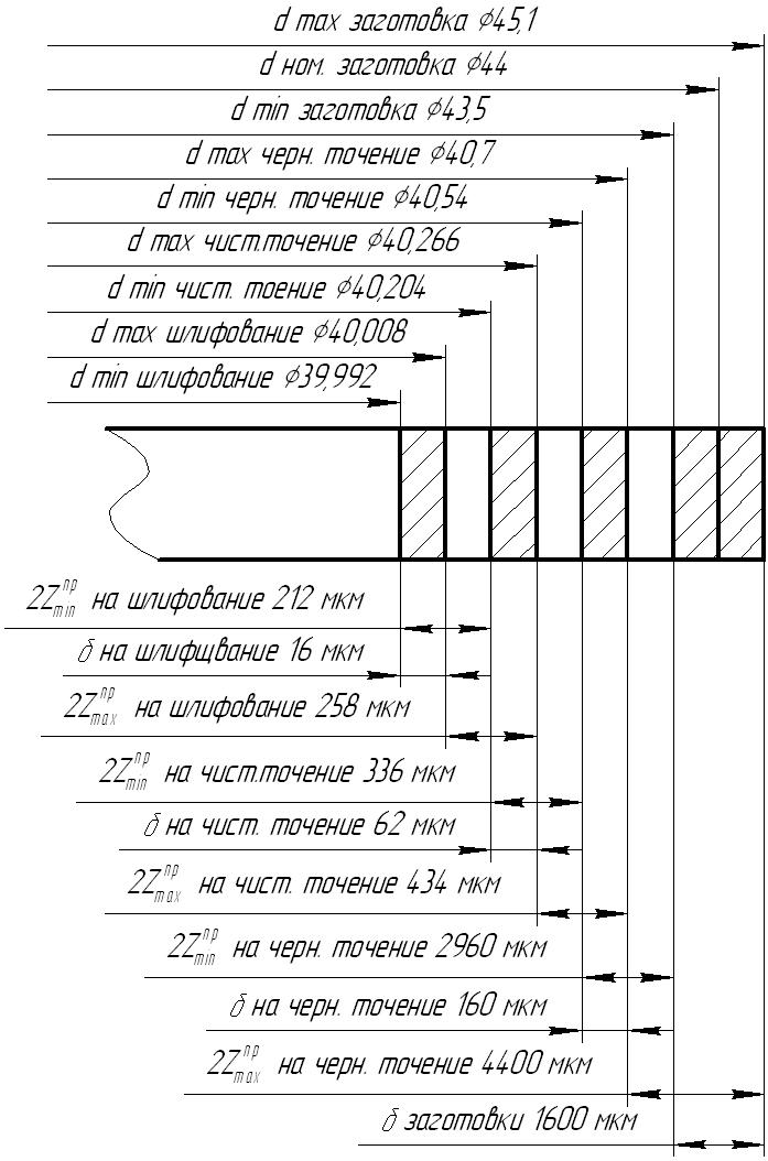
Fig.1. Scheme of allowances and tolerances for size 40 js6 mm.
1.7 Operating technology design
1.7.1 Calculation of cutting conditions and time standards
1.7.1.1 Designing operation No. 010 "CNC turning"
The operation is performed on a CNC screw-cutting lathe mod. 16K20F3 for four setups (A and B - roughing, C and D - finishing), each of which performs one transition. In this operation, a 2-jaw driving chuck with a floating front center and a rotating center installed in the tailstock are used to install and base the workpiece on the machine.
As cutting tools, turning tools for external machining of the ISO standard manufactured by ISCAR are used:
Rough turning:
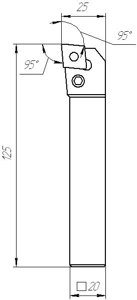
Holder: PCLNR 2020K-12
Plate: CNMG 120408T-NR
corner radius r=0.8 mm
insert grade IC 9025
V=150..250 m/min
S=0.15..0.5 mm/rev
Fine turning:
Holder: SVJCR 2020K-16
Plate: VCMT 160404E-14
corner radius r=0.4 mm
insert grade IC 9025
hard alloy coated by chemical deposition with three layers of TiN, AL 2 O 3 , TiCN.
V=250..400 m/min
S=0.12..0.25 mm/rev
All calculations for this operation are carried out according to the formulas
The cutting speed for external longitudinal and transverse turning is calculated by the formula

Kv for cutting speed is the product of the individual coefficients
TOmv
Knv - the influence of the state of the surface of the workpiece (for rolled products = 0.8; after roughing = 1.0) Table 5,
Kuv – influence of the material of the cutting part (= 1.9) table.6
Kf – influence of the main angle in the cutter plan (for f95Å=0.7; for f93Å=0.7)Table 18
Rough turning (Settings A and B):
Depth of cut t = 4 mm
Feed S=0.5 mm/rev
WITH V= 350 tab.17
m= 0,2
 = 0,15
 = 0,35
We choose the nearest value according to the passport of the machine 800 rpm
Determine the cutting force:
P z =10 C p t x s y v n K p
General correction factor Cr K p = K mp K p K p K p K rp
K mp =0.75 tab.9
K j p=0.89 tab.23
K g p =1,1
K l p =1,0
K rp
K p = 0,75*0,89*1,1*1=0,734
WITH p= 204 table 22
n = 0
P z =10*204*4 1 *0,5 0,75 *135,7 0 *0.734=3561 N
Calculate cutting power
To=  .
.
Lpx:
Lpx=Lcut+y+ Ladditional
where Lcut -
Ladd -
y –
For setup A:
Lcut= 430 mm
Lextra+y= 14 mm
Lpx= 444 mm
To=  1.11 min
For setup B:
Lcut= 187 mm
Lextra+y= 14 mm
Lpx= 201 mm
To=  0.503 min
Fine turning (Settings C and D):
Depth of cut t = 0.4 mm
Feed S=0.25 mm/rev
Tool life T = 60 min
WITH V= 420 tab.17
m= 0,2
We choose the nearest value according to the passport of the machine 2000 rpm
Actual cutting speed
Determine the cutting force:
P z =10 C p t x s y v n K p
General correction factor Cr on the cutting force is the product of the individual coefficients K p = K mp K p K p K p K rp
K mp =0.75 tab.9
K j p=0.89 tab.23
K g p =1,1
K l p =1,0
K rp– is taken into account only for high speed steel.
K p = 0,75*0,89*1,1*1=0,734
WITH p= 204 table 22
n = 0
P z =10*204*0,4 1 *0,25 0,75 *333,01 0 *0.734=211.76 N
Calculate cutting power
 kW
kW
 kW
kW
Let's determine the main machine processing time:
To=.
Determine the stroke length Lpx:
Lpx=Lcut+y+ Ladditional
where Lcut - cutting length equal to the processing length.
Ladd - additional stroke length, caused in some cases by the features of the setup and configuration of the part.
y – length of approach, plunge and tool overrun
For installation B:
Lcut= 432 mm
Lextra+y= 6 mm
Lpx= 438 mm
To=  0.876 min
To install G:
Lcut= 196 mm
Lextra+y= 6 mm
Lpx= 202 mm
To=  0.404 min
Determination of the piece-calculation time for the operation.
The technical norms of time in the conditions of mass and mass production are established by the calculation and analytical method. In serial production, the norm of piece-calculation time is determined:
Tsh-k=  + Tsht,
where Tpz - preparatory - the final time for the operation.
n – the size of the launch batch of parts; n= 280 pcs
The rate of piece time when machining on CNC lathes is defined as:
T PC =T O +T v +T service +T lane
TO - main technological time
Tobsl - maintenance and service time.
Tper- break times .
TV - auxiliary time:
T v =T mustache +T m.v + T zo + T from
Tm.w. - machine-assisted time required to move the turret of the machine in the processing area, including idle withdrawals and supplies, as well as tool change.
Tzo - time for fastening and unfastening the part,
Tus -,
Teese - time to measure the part,
T m.v. =T xx +T ck +T si
Txx- total idle time
Tsk - the total time for changing frames of the control program (on average, the time for changing one frame is 1.5-2 seconds).
Tsi - The total time required to change the tool.
T PC =T O +T mustache + T from + T zo +T xx +T ck +T si +T service +T lane
The total length of idling -1862 mm
Rapid travel speed - 2000 mm/min
Txx=1862/2000= 0.931 min
Tsi= 0.17 min
Tsk=1.5 min
Tm.w.\u003d 0.931 + 1.5 + 0.17 \u003d 2.601 min
 2.893+0.4+2.601=5.894 min
Tobsl+ Tper=12% of operational time
Tobsl+ Tper=5,894*0,12=0,707
The obtained values of the norms of time are summarized in Table 3.
Table 3
|
Set A |
Set B |
Set B |
G settings |
||
|
T mustache , min |
|||||
|
T zo , min |
|||||
|
T from , min |
|||||
|
T service +T lane , min |
|||||
|
T pz , min |
|||||
|
T O , min |
Based on the table we get:
T PC =2,893+0,74+ 2,64 + 0,176 +2.601+2.828=11.878 min.
Tsh-k=  +11.878=11.942 min.
1.7.1.2 Designing operation No. 020 "Milling"
The operation is performed on a keyed milling machine 6D91 in two setups. For this operation, it is necessary to use a special device, by means of which the part is installed and based on the machine along the outer cylindrical surface and end (assembly drawing of the device is presented on a sheet of format A1 PenzGU 1.3-09.151001.123.005-SB).
Special cutters are used as cutting tools:
for setting A - key cutter 12  mm, cutter material - high-speed steel R6M5
for setting B - fungal cutter 48 mm and b = 8 H8 mm, cutter material - high speed steel R6M5
All calculations for this operation are carried out according to the formulas.
Set A:
The part is installed on the fixture and based on 40.2 (drawing 40js6).
At this transition, a groove is milled for a parallel key with dimensions V=12 ,
t=
4.5H12. Processing is carried out by the "pendulum" method in two passes with a feed to a depth of 2.2 mm
,
t=
4.5H12. Processing is carried out by the "pendulum" method in two passes with a feed to a depth of 2.2 mm
Milling depth t=2.2 mm
Milling width H=12 mm
Cutter diameter D=12 mm
Feed per cutter tooth Sz= 0.18mm/tooth
Number of cutter teeth z=2
Determine the stroke length Lpx:
Lpx=Lcut+y+ Ladditional
where Lcut - cutting length equal to the processing length. Lcut= 54 mm
Ladd - additional stroke length, caused in some cases by the features of the setup and configuration of the part.
y – length of approach, plunge and tool overrun
Lextra+y=6 mm
Lpx = 54+6=60mm
Determine the cutting speed V n,
min  ,
,

The total correction factor Kv for cutting speed is the product of the individual factors 
TOmv- the influence of the quality of the processed material (for steel = 0.9) Table 3,
Knv
Kuv –
T - tool life; T= 80 min tab40;
WITH V= 12 table 39
m = 0,26
q= 0,3
u= 0
p= 0
Spindle speed:
n= 250 min
Specifying the cutting speed:
Define the minute feed Sm, mm/min:
Sm=Sz* z* n= 0.18*2*250=90mm/min
Determine the cutting force:
P z =10
correction factor K mp for cutting force
K mp =0.3 tab.9
WITH p= 82 table 41
u = 1
q= 0,86
P z =10
 H
H
Calculate cutting power
 kW
kW
 kW
kW
Let's determine the main machine processing time:
To=  min
min
Setting B:
The part is installed on the fixture and is based on Ç32.4 (drawing Ç32.2n6).
At this transition, the groove for the key is milled with dimensions V=8 +0,022 , t= 4 H12. Processing is carried out with a fungal cutter Ç48 mm and b = 8 H8 mm, the material of the cutter is high-speed steel R6M5
Milling depth t=4 mm
Milling width H=8 mm
Cutter diameter D=48 mm
Feed per cutter tooth Sz= 0.01 mm/tooth
Number of cutter teeth z=12
Determine the stroke length Lpx:
Lpx=Lcut+y+ Ladditional
where Lcut - cutting length equal to the processing length. Lcut= 54 mm
Ladd - additional stroke length, caused in some cases by the features of the setup and configuration of the part.
y – length of approach, plunge and tool overrun
Lextra+y=6 mm
Lpx = 54+6=60mm
Determine the cutting speed V, m/min, spindle speed n, min,
The total correction factor Kv for cutting speed is the product of the individual factors
TOmv- the influence of the quality of the processed material (for steel = 0.9) Table 3,
Knv - the influence of the state of the surface of the workpiece (after processing = 1.0) Table 5,
Kuv – influence of the material of the cutting part (= 1.0) table.6
T - tool life; T= 60 min tab40;
WITH V= 72 table 39
m = 0,15
q= 0,2
u= 0,1
p= 0,1
Spindle speed:
According to the passport of the machine, we accept the number of revolutions n= 1000 min
Specifying the cutting speed:
Define the minute feed Sm, mm/min:
Sm=Sz* z* n= 0.01*12*1000=120mm/min
Determine the cutting force:
P z =10
correction factor K mp for cutting force
K mp =0.3 tab.9
WITH p= 68.2 tab.41
u = 1
q= 0,86
w= 0
P z =10
 H
H
Calculate cutting power
 kW
kW
 kW
kW
Let's determine the main machine processing time:
To=  min
min
Tsh-k = + Tsht,
where Tpz -
n – n= 280 pcs
Tsht=To+Tvk+Tob.from,
where That - main time,
TV - auxiliary time:
TV=Tus+Tzo+Tup+Tiz,
where Tus - installation and removal time ,
Tzo -
Stupid -
Teese - time to measure the part,
Tob.from –
k k=1,85).
Tob.ot=T op ·9 %
T op =T O +T v · k
T op =2.833+(0.094+0.068+0.12+0.62)1.85=4.502 min
Tob.from \u003d 4.502 0.09 \u003d 0.405 min
The obtained values of the norms of time are summarized in table 4.
Table 4
|
Name |
Transition 1 |
Transition 2 |
|
|
Tus - |
|||
|
Tzo - |
|||
|
Stupid - |
|||
|
Teese - |
|||
|
Tob.from - |
|||
|
Tpz - |
|||
|
That– main time, min |
|||
Tsh-k=  +4,502+0,405
= 5.004 min.
+4,502+0,405
= 5.004 min.
1.7.1.3 Designing operation No. 025 "Thread-cutting"
The operation is performed by a thread-cutting semiautomatic device 5D07 in two settings. For this operation, it is necessary to use a device - a vice with self-centering jaws, by means of which the part is installed and based on the machine along the outer cylindrical surface. It is possible to use a special device similar to the device used in the milling operation.
As a cutting tool, a self-opening screw-cutting head is used - 4KA-70 according to GOST 21760 - 76 with a round comb according to
GOST 21761-76 made of R6M5 high-speed steel with a wear-resistant coating of titanium nitride (TiN)
All calculations for this operation are carried out according to the formulas.
1) Set A:
The part is installed on the fixture and is based on the surface of the neck Ç38js6.
At this transition, threading M24 × 1.5-6g is performed.
Feed (equal to thread pitch) S= 1.5mm/rev
Thread diameter D=24 mm
Depth of cut t=1.3 mm
Lpx:
Lpx=Lcut+y+ Ladditional
where Lcut - cutting length equal to the processing length. Lcut= 31 mm
Ladd - additional stroke length, caused in some cases by the features of the setup and configuration of the part.
Y – length of approach, plunge and tool overrun
Lextra+y=3 mm
Lpx = 31+3=34mm
Determine the cutting speed V, m/min, spindle speed n, min,

TOmv
K T v
Kuv –
T - tool life; T= 120 min tab49;
WITH V= 7.4 tab.49
m = 0,5
q= 1,2

Spindle speed:
According to the passport of the machine, we accept the number of revolutions n= 160 min
Specifying the cutting speed:
Determine torque:
M KP =10 C M D q S y K mp
correction factor K mp for cutting force
K mp =0.85 tab.50
WITH M= 0.046 table 51
q= 1,1
M KP =10 0.046 24 1,1 1.5 1,5 0.85=23.69Hm
Calculate cutting power
 kW
kW
 kW
kW
Let's determine the main machine processing time:
To=  min
min
2) Setting B:
The part is installed on the fixture and is based on the surface of the neck Ç32,2n6.
At this transition, threading M24 × 1.5-6g is performed
Feed (equal to thread pitch) S= 1.5mm/rev
Thread diameter D=24 mm
Depth of cut t=1.3 mm
Determine the stroke length Lpx:
Lpx=Lcut+y+ Ladditional
where Lcut - cutting length equal to the processing length. Lcut= 20.4mm
Ladd - additional stroke length, caused in some cases by the features of the setup and configuration of the part.
y – length of approach, plunge and tool overrun
Lextra+y=3 mm
Lpx = 20.4+3=23.4mm
Determine the cutting speed V, m/min, spindle speed n, min,
The total correction factor Kv for cutting speed is the product of the individual factors
TOmv- the influence of the quality of the processed material (for steel = 0.8) Table 50,
K T v - taking into account the accuracy of the thread being cut (accurate = 0.8) Table 50,
Kuv – influence of the material of the cutting part (= 1.0) tab.50
T - tool life; T= 120 min tab49;
WITH V= 7.4 tab.49
m = 0,5
q= 1,2
Spindle speed:
According to the passport of the machine, we accept the number of revolutions n= 160 min
Specifying the cutting speed:
Determine torque:
M KP =10 C M D q S y K mp
correction factor K mp for cutting force
K mp =0.85 tab.50
WITH M= 0.046 table 51
q= 1,1
M KP =10 0.046 24 1,1 1.5 1,5 0.85=23.69Hm
Calculate cutting power
Let's determine the main machine processing time:
To=  min
min
3) Determination of the piece-calculation time for the operation.
The technical norms of time in the conditions of mass and mass production are established by the calculation and analytical method. In serial production, the norm of piece-calculation time is determined:
Tsh-k = + Tsht,
where Tpz - preparatory - the final time for the operation.
n – the size of the launch batch of parts; n= 280 pcs
Tsht=To+Tvk+Tob.from,
where That - main time,
TV - auxiliary time:
TV=Tus+Tzo+Tup+Tiz,
where Tus - installation and removal time ,
Tzo - time for fastening and unfastening the part,
Stupid - time for appointments machine control,
Teese - time to measure the part,
Tob.from – time for maintenance of the workplace and breaks for rest and personal needs,
k- coefficient taking into account the serial production ( k=1,85).
Tob.ot=T op 7%
T op =T O +T v · k
T op =0.24+(0.094+0.068+0.12+0.55)1.85=1.78 min
Tob.ot \u003d 1.78 0.07 \u003d 0.125 min
The obtained values of the norms of time are summarized in Table 5.
Table 5
|
Name |
Transition 1 |
Transition 2 |
|
|
Tus - installation time and removal of a part, min |
|||
|
Tzo - time for fastening and unfastening the part, min |
|||
|
Stupid - time for machine control, min |
|||
|
Teese - time to measure the part, min |
|||
|
Tob.from - time for maintenance of the workplace and breaks for rest and personal needs, min |
|||
|
Tpz - preparatory - final time, min |
|||
|
That– main time, min |
|||
|
Time to receive and return the instrument, min |
|||
Based on the table we get:
Tsh-k= +0,24+0,125 = 0.46 min.
1.7.2 Calculation of machining accuracy
The calculation of machining accuracy consists in determining the total error of fine turning and comparing it with the dimensional tolerance according to the 9th grade of accuracy 40.266 h9 (-0.062).
The total processing error is calculated by the formula
where - errors arising in the process of processing;
 - the error of setting the technical system to the size.
1. Determine the machining error caused by the dimensional wear of the tool 
Using table 29 of the permissible dimensional wear of the tool when processing a batch of workpieces, we determine:
 20 µm
20 µm
2. Define the elastic push-downs caused by the inconsistency of the force 
Since the surface treatment took place with fixing in machine cams, the following formula applies here
Compliance  is equal to
 µm/kN
µm/kN
Radial force  define by the formula
where  mm;
mm;  mm
mm
Cutting speed value: m/min.
According to Table 22 we find: WITH p = 204; n = 0; X= 1,0; Y= 0,75
The value of the correction factor for cutting force
K p =0,734
Calculate the cutting speed and determine the radial force
Let's define elastic push-ups
3. Let us determine the error of setting the technical system for the size
 µm.
µm.
4. Temperature deformations are determined by the formula
 ,
,
 micron
5. Determine by the formula

 ,
,
 mm,
mm,
 mm;
mm;
 µm.
µm.
Total processing error
We compare the total error with the size tolerance 40.266 h9, which is 62 µm.
62 µm > 55.5 µm
Conclusion: the accuracy of machining is observed.
1.7.3 Equipment selection
At the enterprises, they try to paint the technological route in such a way that, if possible, all of it is carried out on the equipment of one workshop. This is due to the need to draw up a lot of documents when moving part of the route process to another shop.
The designed technology satisfies this rule. All its operations are performed within one section of the workshop, except for the harvesting operation.
The choice of a specific model of equipment is carried out according to overall, accuracy and power criteria.
The distribution of equipment by operations is summarized in Table 6.
Table 6
|
Machine name |
Cutting tool |
Device and auxiliary tool |
measuring tool |
|
|
Milling and centering semi-automatic |
Drill 4 R6M5 GOST 14034-74 Drill center. 2317-0107 (f4.00) GOST 14952-75 End mill Ø 100 T5K10 GOST 24359-80 Cutter (f100) 2214-0001 T5K10 45° GOST 24359-80 |
|||
|
Screw-cutting lathe CNC 16K20F3 |
Through cutter PCLNR 2020K-12 with insert: CNMG120408T-NR Straight cutter SVJCR 2020К-16 |
Chuck 2 x cam |
Micrometer MK 25-1 GOST 6507-78 Caliper ШЦ-I-125-0.1-1 GOST 166 Roughness samples GOST 9378-75 |
|
|
Keyway milling machine 6D92 |
Special key cutter Ç12mm P6M5 Cutter (f12) 2234-0367 N9 GOST 9140-78 Special fungal cutter Ç48 mm and b=8 H8 R6M5 |
Special device |
Caliper ШЦ-I-125-0.1-1 GOST 166 |
|
|
Thread-cutting semiautomatic device 5D07 |
Comb 2671-0773 GOST 21761-76 |
Head 2681-0023 GOST 21761-76. Vise with self-centering jaws |
Threaded ring М24×1.5. Pr and NOT. |
|
|
Circular grinding machine 3M151 |
Grinding wheel PP300×30×24A40PS1-S2 6K5 50 m/s 1kl.A GOST 2424-83 |
Center front, rear GOST 13214-79 Collar GOST 16488-79 |
Staples Ave. and NOT. Roughness samples GOST 9378-75 |
Drill 2300-6173 (f5.00) GOST 10902-77
Caliper ШЦ-I - 250-630 - 0.05-1 GOST 166-89
Caliper ШЦ-I - 125 - 0.05-1 GOST 166
Caliper ШЦ-I - 125 - 0.10-1 GOST 166
Tripod ШМ-I-8 GOST 10197-70
Indicator ICH02 cl. 1 GOST 577-68
Goniometer type 1-2 GOST 5378-88
Micrometer MK50-1 GOST 6507
Micrometer MK25-1 GOST 6507-90
Bracket 061 OST 95 1960-78 on cut. diameter
Bracket СР 50 GOST 11098-75
Ring 8211-0094 6g (M24 X1.5-PR) GOST 17763-72
Ring 8211-1094 6g (M24 X 1.5-NOT) GOST 17764-72
Cork 8133-0630 (f5) H14 GOST 14807-69
2. Design of technological equipment, measuring and cutting tools
2.1 Selection and justification for installing a part in a fixture
From the drawing of the part, it follows that for the operation of milling the keyway, a special fixture should be used to clamp the part on the machine. In it, the workpiece is based on a prism and two supports. Since the fixture is used in large-scale production, it must be equipped with a quick clamping device. These requirements are met by the pneumatic drive of the clamping mechanism.
2.2 Technical description of the design and principle of operation of the device
The device consists of a body, an installation prism, a lever clamping device. A single-acting piston pneumatic cylinder is adopted as a drive when compressed air is supplied to the upper part of the pneumatic cylinder, the piston with the rod descends and presses the part by means of a lever transmission, i.e. the part is fixed. When the supply of compressed air to the upper cavity is stopped, the springs mounted on the clamping mechanism raise the clamp, and with it the rods and the piston rod rise up and the part is released.
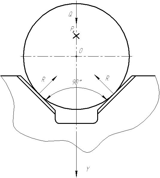
2.3 Development of a design scheme for fastening and calculation of the clamping mechanism
The workpiece is based on the mounting elements of the fixture and is pressed against them by a clamp with a force Q, and the cutting force P o acts in the perpendicular direction. The cutting force P o is counteracted by the friction force T between the support surface of the fixture and the lower base plane of the part, as well as between the upper plane of the part and the clamping surface.
 Rice. 4
Let us compose the equation of equilibrium of all forces acting on the workpiece relative to the Y axis:
ΣF yi =Q – 2Rsina/2=0
The required clamping force is determined from the expression:
kP o \u003d Qf 1 + 2Rf 2
 , where
k-clamp safety factor.
k 0 =1.5 - guaranteed safety factor.
k 1 \u003d 1.0 - coefficient taking into account the change in allowance
k 2 \u003d 1.4 - coefficient that takes into account the increase in cutting force when the tool becomes dull.
k 3 \u003d 1.2 - coefficient taking into account the increase in cutting force with interrupted cutting
k 4 \u003d 1.0 - coefficient taking into account the constancy of clamping forces
k 5 \u003d 1.0 - coefficient characterizing only manual clamping mechanisms
k 6 \u003d 1.0 - coefficient taking into account the presence of a moment tending to rotate the workpiece.
a=  - prism angle
f 1 \u003d f 2 \u003d 0.15

Clamping mechanism calculation:


Determine the size of the drive:
R and =0,785 D 2 ph
p \u003d 0.4 N / m 2 \u003d 4 kgf / cm 2 - specific pressure of compressed air;
 =0,7.
=0,7.
Round the resulting diameter to the nearest value.
Rod diameter: d=0.25D=0.25*100=25 mm.
List of used literature.
A. F. Gorbatsevich. Course design for engineering technology. Minsk: Higher School, 1983.
A. G. Kosilova and R. K. Meshcheryakov. Handbook of technologist machine builder. In two volumes. Volume 2. M .: "Engineering", 1985.
"Metal cutting modes". Handbook edited by Yu.V. Baranovsky. M. "Engineering", 1972.
A. G. Kosilova and R. K. Meshcheryakov. Handbook of technologist machine builder. In two volumes. Volume 1. M .: "Engineering", 1985
A.K. Goroshkin. Device for metal-cutting machine tools. Handbook 7th edition, revised and supplemented. M.: Mashinostroenie 1979
"Metal Machining": Handbook edited by A.A. Panova. - M.: Mashinostroenie, 1988.
B.L. Bespalov, L.A. Glazer, I.M. Kolesov Engineering technology M., “Engineering”, 1973
Design of automated engineering technology: Proc. for mechanical engineering. specialist. universities/ THEM. Baranchukova, A.A. Gusev, Yu.B. Kramarenko and others; ed. Yu.M. Solomentsev. - 2nd ed., Rev. - M .: Higher. school, 1999
Parts of the class "shafts" are characterized by the fact that they are mainly formed by external surfaces of rotation about one axis. The length of the shaft is much greater than the diameter.
In some designs, an internal central hole may be present.
In terms of purpose, design, weight, processing accuracy, material and other indicators, parts of this class are very diverse.
In rolling equipment, shafts weighing from several kilograms to 20-30 tons and even more with diameters up to -800-1200 mm are used.
The class "shafts" is divided into the following main groups: shafts and axles are smooth; stepped; hollow; with shaped curvilinear and conical surfaces.
In each group, the shafts are divided into types, which differ only in the size of the surfaces to be machined.
When processing parts of the "shafts" class, it is necessary:
1. Keep the axis straight. The alignment and straightness of all sections of the shafts and axles must be within the established tolerances.
2. Keep the surfaces of revolution concentric about the axis. The ellipticity and taper of the machined necks must be within the diameter tolerance.
3. So that the value of the radial runout of the shaft bearing journals to the locating journals is maintained within 0.02-0.03 mm.
4. Treat the surfaces of the bearing journals for gears, pulleys and flywheels with class 6 cleanliness, for rolling bearings with class 7 cleanliness, and roll barrels with class 7-8 cleanliness.
5. Cut the ends and ledges exactly perpendicular to the axis.
6. Give the keyways, splines and clubs the correct profile and place them in a certain place on the surface of the shaft.
7. Maintain the hardness of the working surfaces specified by the designer.
The choice of a workpiece for the shaft is determined by the purpose of the shaft, the brand of material from which the shaft should be made, and its design features.
For most general purpose shafts, carbon steel grades St. 5, Art. 6, steel 40 and 50. Particularly critical shafts are made from high-alloy steels: chromium, chromium-molybdenum, chromium-silicon, etc. For the manufacture of rolling rolls, in some cases alloyed cast irons with the addition of chromium and nickel and modified cast irons are also used - in which magnesium is a modifier . The hardness of the working surfaces, depending on the purpose of the rolls, ranges from 30 to 75 Shore units.
Shaft blanks are pre-treated in the following order; editing, marking, cutting, trimming and centering, control.
The main operations in the processing of shafts are turning, during which the bulk of the material is removed - the allowance, as a result of which the shaft is given the necessary shape and dimensions of the main surfaces.
Rough turning provides 4-5th accuracy classes and 3-4th cleanliness classes. Processing is carried out with a depth of cut of 5-25 mm or more, with feeds of 0.5-3 mm/rev and at cutting speeds of 30-40 m/min. When roughing rolled products, good results are obtained in the case of using cutters with high-speed steel plates. When processing heavy forgings, the best results are obtained with cutters with T5K10 and T15K6 hard alloy inserts. Roughing is carried out mainly according to the principle of power cutting. To reduce the main time and the full use of the machine, the following measures are used:
Two cutters are installed in the caliper, each of them has a different reach, removes a certain part of the allowance in depth;
Apply cutters with several cutting edges, which "can cut with the forward and reverse stroke of the caliper;
Step cutters are used, which reduce the solid - chip width and thereby reduce the cutting force;< ,
When processing long and heavy shafts, two and three calipers are used, using the front and rear calipers of the machine.
Shaft roughing is usually done in two settings. For turning, straight or bent right and left through cutters are used, for cutting ends and ledges - undercut and for processing fillets - special curved and concave fillet cutters. Fillets of large radius (30 mm and above) are often cut either by combining longitudinal and transverse feeds according to templates, or using a special rotary device mounted on the cross slide of the caliper.
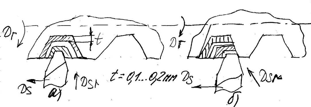
When processing stepped shafts, it is advisable to process the more massive steps with a large diameter first. The most widespread are two schemes for processing stepped shafts (Fig. 45).
With a small difference in the diameters of the steps, the scheme of Fig. 45, a, with a significant difference in diameters and shafts of large diameter - the diagram of Fig. 45, b. Sometimes combined processing is used using both schemes. You should choose the method that provides the best performance and more full use machine.
When turning conical and shaped surfaces, they use a combination of longitudinal and transverse feeds, processing according to templates, or copiers are used.
The first method, which requires high qualification of the performer, is used in single and small-scale production.
Short and steep cones are machined by turning the upper slide of the caliper and feeding the cutter at an angle equal to half the angle of the cone. Long and shallow cones are turned by mixing the tailstock so that the generatrix of the cone is parallel to the spindle axis and the longitudinal movement of the cutter. This method is quite simple and can be used on any lathe, but there is uneven operation and wear of the centers, as well as a breakdown of the center holes.
When processing shaped surfaces of small length, special shaped cutters are used, which are usually processed with a transverse feed. The profile of the cutter along the cutting edge corresponds to the reverse profile of the part. Of the shaped cutters, threaded, fillet, and groove cutters are more often used in metallurgical engineering.
When processing a hollow shaft from a solid workpiece, after marking, milling the ends and centering, a rough turning is performed outer surface by mounting the shaft at centers and chuck. The hole is drilled and bored either on a lathe with steady rest or on a horizontal boring and boring machine. Recently, drilling with hollow drills has become widespread, when the core is removed in the form of a separate shaft. A similar method is used for holes with a diameter of more than 100 mm.
Depending on the specifications the shaft after roughing can be transferred to finishing or to intermediate heat treatment with subsequent mechanical finishing. In all these cases, an allowance must be left after roughing. Allowances for fine turning after rough turning of rolled blanks are left 0.5-2 mm per side. For forged shafts, the allowances are taken to be 2.5-5 mm, which is explained, on the one hand, by large overall dimensions shafts, and on the other hand, by the fact that roughing was carried out under more difficult conditions, with greater efforts and thermal deformations, as a result of which the surface layer was damaged to a greater depth. If, after roughing, thermal processing is performed, then the allowances are increased by about 1.5-2 times in order to compensate for possible deformation and damage to the surface layer of the part when heat treatment.
The workpiece prepared for heat treatment must repeat all the differences in diameters between the shaft steps. But if the difference in the diameters of adjacent steps does not exceed 10 mm, then they are turned by one diameter. There should be no sharp transitions or corners. During heat treatment in the form of normalization or aging, the structure is improved and internal stresses are eliminated. With a significant allowance after heat treatment, the operation is divided into two transitions: semi-finishing and finishing. The latter is produced at a cutting depth of 1-2 mm.
In the finishing pass, the cutters have a rounded top with a radius of 2-3 mm or a wider cutting edge with Zcp = 0°, which is typical for Kolesov-type cutters, which allow you to work with an increased feed of 1-2.5 mm/rev and provide with careful work cleanliness 6th grade.
If there are no heavy grinding machines in the workshop, and on a large shaft it is necessary to withstand separate steps according to the 2nd class, then they are turned with wide spring cutters with a cutting depth of not more than 0.1-0.3 mm. When the cleanliness of the 7th class is required, the roller is run in, which is installed in a special holder in the machine support. Roller treatment provides not only high cleanliness, but, by creating some work hardening on the surface, increases its density and wear resistance.
There is no special allowance for rolling with a roller. In practice, the allowance is within the tolerance of 0.01-0.02 mm per side.
When finishing and finishing, it is necessary to pay attention to the accuracy of the installation of the shaft and tool, to the rigidity of the entire system, to the geometry of the cutting tool and to the quality of the locating surfaces: center holes (when machining in the center - pax) and machined belts and necks (when machining in lunettes). Cutting forces and thermal influences on the part should be kept to a minimum. In some cases, the processing of shafts is complicated by the fact that keyways, slots or clubs can be located on their surface.
For processing keyed paeov, the shaft is marked, and then transferred to a milling machine.
For small and medium shafts, the keyways are machined on vertical milling and keyway milling machines with end or special keyway cutters. In the first case, when making closed grooves, it is necessary to drill to insert the cutter. Heavy shafts are milled according to markings on horizontal boring and longitudinal milling machines with end and end mills - the latter are widely used in the processing of tangential keyways.
Slotted grooves are processed by the division method or the rolling method. With the division method, marking is preliminarily made, and for small and medium shafts, a dividing head is also used. Cutting according to the rolling method is carried out on special slot-milling machines using worm slotted cutters.
The processing of clubs at the ends of rolling rolls is carried out on boring machines for marking or on special single-sided and double-sided club-milling machines. The cutting tool is either cutters mounted on the mandrel or in the machine spindle, or special club-milling heads.
If the rolling rolls for transmitting rotation have flat blades with a cutout at the ends, then the following operations are necessary when processing these blades:
I. Marking - draw center lines.
II. Planing - planing the blade -
PI. Marking - mark the pharynx.
IV. Drilling - drill the throat.
V. Locksmith - knock out the drilled part of the pharynx. .
VI, Boring - on a boring machine, mill the shed along the inner contour.
The last operation can also be performed on a portable cross planer. The choice of one or another machine is determined by the availability of equipment, the size of the throat and economy. As an example, the following is a process flow for processing the stepped shaft shown in FIG. 46. Shaft material - chromium steel 20XA with tensile strength av = 65 kg / mm2 - Billet - forging obtained by free forging. Allowances are selected according to the standards.
The sequence of operations during processing is as follows: I. Marking - mark the blade.
II. Boring - mill the ends, reduce the center lines, mark the center and center.
6 Order 222
III. Turning - turn to size, cut ends and ledges
IV. Marking - mark the keyway.
V. Milling - milling the keyway.
Fig. 46. Stepped shaft and its blank.
VI. Grinding - grind necks.
VII. Turning - process fillets and cut ends and ledges to size.
VIII. Locksmith - remove burrs.
This TP includes the following operations:
Facing, centering
Turning (turning) of shaft journals
Pre-grinding
Keyway milling
spline milling
Thread processing
heat treatment
Fixing center holes
Fine grinding of shaft journals
Spline grinding
Thread calibration and deburring
flushing
Control
1.2.1. Shaft facing and centering
In single and small-scale production, the ends are processed on turning and milling machines. Centering is performed on drilling, turning, revolving and horizontal boring machines.Centering can be done either with two tools (twist drill and countersink) or with one combined center drill. The taper angle of the drill is usually 60 0 , however, for heavy shaft blanks it is increased to 75 0 or 90 0 .
In some cases, cutting tools have an additional chamfer with an angle of 120 0, which protects the center hole from nicks in case of accidental damage to the ends of the shaft.
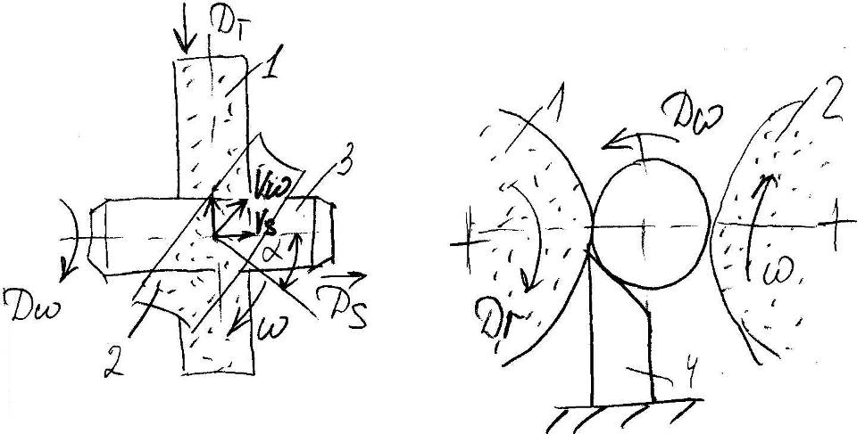
In serial and mass production, semi-automatic milling and centering machines are used, on which 2 ends are milled simultaneously (position 2 in Fig. 1.3.), Then 2 holes are centered (position 3).
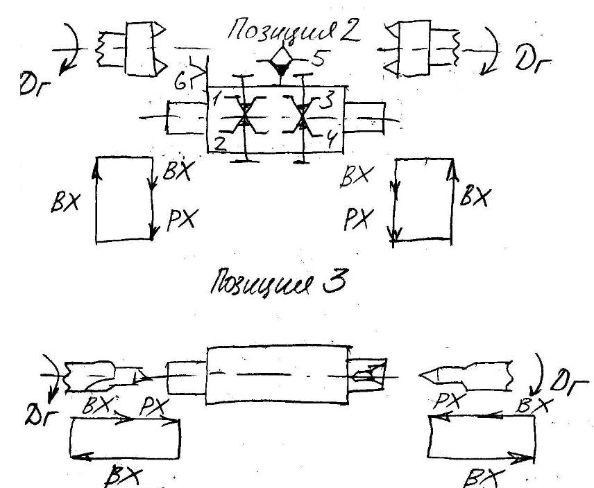
Rice. 1.3. - Scheme of shaft processing on a milling-centering semiautomatic device.
1.2.2. Shaft turning
Shaft turning usually includes roughing and finishing operations. In rough turning, most of the allowance is removed by working with a greater depth of cut and a high feed rate.In single and small-scale production, turning is carried out on turning universal machines. When processing stepped shafts, various cutting patterns are used, for example, shown in fig. 1.4.
In the diagram in fig. 1.4., in the total length of the movement of the cutter  , i.e. less than in the diagram in Fig. 1.4., a. However, the number of working and auxiliary moves is greater.
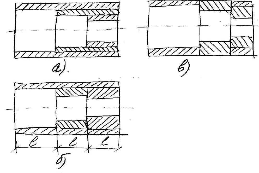
Rice. 1.4. – Shaft turning schemes
When choosing a cutting scheme, they strive to obtain maximum productivity and minimum cost of the operation. At the same time, the dimensions of the shaft, the method of setting and controlling dimensions, tolerances and other factors are taken into account.
Sometimes, with a large difference in the diameters of the steps, they tend not to weaken the shaft for as long as possible and turn the steps of the smallest diameter last.
When turning long non-rigid shafts, fixed or movable steady rests are used. The fixed rest is mounted on the machine bed. The movable steady rest moves on the caliper and its cams follow the cutter (Fig. 1.5., a).
If it is necessary to ensure the alignment of the machined surface with surface 2 (Fig. 1.5., b), then the lunette cams are placed in front of the cutter on the surface.

Rice. 1.5. – Scheme of turning the shaft using a steady rest
Currently, CNC machines are used in small-scale production. They allow you to automate the processing cycle, use increased cutting conditions, increase productivity, apply multi-machine maintenance, reduce the shortage of highly skilled labor, reduce waste, and reduce production preparation time.
In large-scale and mass production for turning shafts, multi-cutting and hydrocopy machines and semi-automatic machines are used. Usually they have 2 calipers - longitudinal and transverse, used for cutting ends, boring grooves and shaped turning.
The calipers can work simultaneously. On multi-cutting machines, if necessary, turning with plunge and subsequent longitudinal feed is used (Fig. 1.6., b).
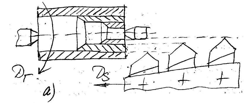
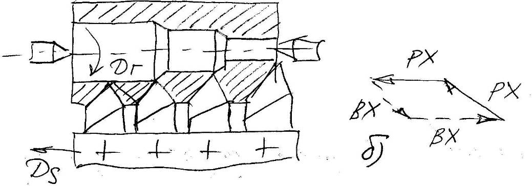
Rice. 1.6. - The scheme of turning the shaft on a multi-cutting semi-automatic
Compared to general-purpose lathes, multi-tool lathes increase productivity by shortening the stroke length, simultaneous operation of the cutters, and by eliminating the time spent changing cutters, turning the tool post, and idle movement of the caliper.
On the longitudinal support of the hydrocopy machine, 1 cutter is installed, which is adjusted to the size of only one shaft neck. Obtaining the remaining dimensions is provided by a copier and a tracking system. At the same time, the number of measurements is reduced, a higher cutting mode is applied than when working with manual feeds.
The shafts are turned in one or several working strokes, while the copiers are changed automatically by rotating the drum with the copier.
In cases where the shaft can be processed on a hydrocopy and single-spindle multi-cutting semi-automatic machine, the choice of equipment is made on the basis of a feasibility study.
This takes into account the following considerations:
With multi-cut turning with a division of the processing length, the length of the working stroke is less than with copy processing.
The set-up and re-adjustment time for hydrocopy machines is much less than for multi-cutter machines.
The number of cutters and cutting conditions on multi-cutting machines are often limited by workpiece compliance and insufficient machine power. On a hydrocopy machine, it is possible to work with high feed rates of the main cutting movement.
In connection with the above, the productivity of hydrocopy machines is in many cases higher.
The accuracy of multi-cutting processing is affected by errors in the relative position and uneven wear of the cutters. When processing one surface with several cutters, ledges are formed at the boundaries of the sections. On hydrocopy machines, these errors are absent, so it is possible to obtain higher dimensional accuracy and less roughness.
1.2.3. Finishing of external cylindrical surfaces
Fine turning, grinding, polishing, lapping, superfinishing, roller turning, etc. are used for finishing the outer cylindrical surfaces.1.2.2.1. fine turning
Fine turning is more often used for finishing workpieces made of non-ferrous metals and alloys, less often for workpieces made of steel and cast iron. This is explained by the difficulties of grinding non-ferrous alloys due to the "loading" of the grinding wheel.Processing is carried out with diamond, composite, metal-ceramic cutters and cutters equipped with hard alloys, at high speeds of the main cutting movement, low feed speeds and depths of cut.
Fine turning allows you to get 6 ... 7 grade of machining accuracy and surface roughness  µm.
µm.
Machining performance is higher than grinding. In large-scale and mass production for fine turning, special high-speed machines of high accuracy and vibration resistance are used.
1.2.2.2. grinding
It is the main method of finishing the outer cylindrical surfaces. The advantage of grinding is the ability to correct workpiece errors after heat treatment. With conventional fine grinding, processing is carried out according to 6-7 accuracy grades, with a surface roughness of 1.2 ... 0.3 microns.Fine grinding gives the 5th grade of accuracy and a roughness of 0.16 ... 0.8 microns. It is carried out by a small-grained circle at a high speed of its rotation, a low speed of rotation of the workpiece, and a small depth of cut.
Grinding is carried out on round and centerless grinding machines with a longitudinal feed of the circle or according to the method of rotation (Fig. 1.7.)

A - with longitudinal feed; B, C - according to the method (method) of rotation
Rice. 1.7. – Scheme of grinding on a circular grinding machine:
Grinding according to the rotation method is more productive, it is used in large-scale and mass production in the processing of cylindrical and shaped surfaces.
For simultaneous grinding of several necks are used special machines, working with several circles in order to reduce auxiliary time during grinding, active control devices are used to measure workpieces in the grinding process, as well as devices for automatically stopping the machine when a given size is reached.
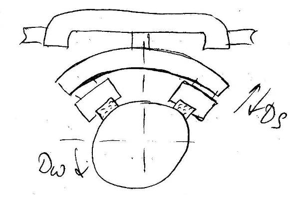
With centerless grinding (Fig. 1.8.), the workpiece is placed between two grinding wheels, of which one (larger diameter) is grinding, and the other is leading.
Rice. 1.8. – Scheme of centerless grinding
Grinding wheel 1 rotates at a speed of 20-35 m/s, driving wheel 2 - at a speed of 20-30 m/min. The workpiece 3 is not fixed by anything, but is supported by a support 4 with a bevel directed towards the leading circle.
The grip force of the workpiece with the driving circle is greater than with the grinding one. This is due to the following reasons:
Increasing cutting force with decreasing wheel speed
Production of leading circles on the connection, which increases the coefficient of friction between the circle and the workpiece.
In centerless grinding with a longitudinal movement of the workpiece feed, the axis of the driving wheel is not parallel to the axis of the grinding wheel. Thanks to this, without special mechanism feed, the workpiece is moved at a speed  where
where  - speed of rotation of the leading circle.
With increasing angle  crossing the axes of the circles, the processing performance increases, but the surface quality deteriorates, so usually
  .
.
To improve the accuracy of processing, through grinding is sometimes performed in several working strokes. In large-scale and mass production, processing can be performed sequentially on several machines connected to an autoline.
In centerless grinding according to the method of plunging, the axes of the circles are most often parallel. First, the leading circle is retracted from the grinding, and the workpiece is placed on the support, then the leading circle is brought to the workpiece and the cross feed is carried out until the specified size is obtained.
Compared to center grinding, centerless grinding has the following advantages:
There is no need to center the workpiece, which is especially important for parts processed on turret machines and automatic machines;
Machining allowances are significantly reduced, because, due to the use of the machined surface as a technological base, the influence of the centering error on the allowance is eliminated;
There is no need to use steady rests when grinding long and thin shafts;
Centerless grinding machines are relatively easy to automate and integrate into an autoline;
Provides higher productivity than when grinding in centers;
Due to the ease of control of the machine, high accuracy is achieved with an average skill of the grinder;
The machining error caused by wheel wear is 2 times less than when grinding in the centers, because wheel wear is directly reflected in the size of the diameter of the workpiece, and not in the size of the radius.
1. The time spent on setting up and adjusting such machines is quite large and pays off with large batches of workpieces. Therefore, centerless grinding is most often used in the automotive and bearing industries.
2. keyways, grooves, holes, breaks in the machined surface impede normal operation and even make it impossible.
3. With centerless grinding, it is difficult to ensure the roundness of the machined surface.
4. It is difficult to achieve alignment of the sanded surface with other previously processed surfaces.
1.2.3.3. Polishing and superfinishing
Polishing with soft wheels made of felt, felt or tape is carried out at high speeds of the tool, on the surface of which a mixture of fine-grained abrasive powder and lubricant is applied. Polishing provides low surface roughness ( µm), but does not change the dimensional accuracy and shape.
 Superfinishing (finishing with oscillating bars) implements the principle of a non-repeating trace, which lies in the fact that no abrasive grain passes twice along the same path. For this, in addition to a rotating workpiece, at a low speed (1-2.5 m / min) and longitudinal movement of the bars (Fig. 1.9.), They are told from 200 to 1000 oscillations per minute with a small amplitude.
Due to oscillatory movements, small grain size of the bars and low pressure, a small roughness of the workpiece is ensured (  µm).
µm).
Rice. 1.9. - Scheme of processing the shaft with abrasive bars.
The process is carried out with the use of a cutting fluid and proceeds as follows: at the initial moment, the contact area of the bars with the treated surface is small and the pressure of the bar is significant, which causes intensive metal removal. In the future, the bars are run in, the pressure decreases, and the cutting process loses its intensity.
Superfinishing does not improve the macro-geometry of the workpiece, so pre-treatment must ensure the correct geometric shape of the part. Superfinish allowance is usually not left.
1.2.4. Thread processing
1.2.4.1. Threading with cutters and combs
At threading On lathes, the workpiece is given rotation, and the cutter is moved along the axis of the workpiece with a feed per revolution equal to the thread pitch. The pitch accuracy is determined by the accuracy of the kinematic chain of the machine, and the accuracy of the thread profile is determined by the accuracy of sharpening and setting the cutter. Therefore, in the process of processing, the turner usually controls ?????????????????????.When cutting threads in several working strokes, the movement of the transverse feed of the cutter can be carried out, for example, according to the schemes shown in Fig. 1.10. (a,b). When using scheme (a), it is provided the best quality processed surface, and when working according to scheme (b), the shape of the cut layer is simplified, the process of cutting and chip removal is facilitated. Therefore, sometimes roughing is performed according to scheme (b), and the last layer is cut off according to scheme (a).
Rice. 1.10. – Cutting patterns for threading.
When threading with one cutter in several working strokes, its cutting edge quickly becomes dull and its shape is distorted, therefore it is recommended to use 2 cutters for threading with a large pitch - roughing and finishing, or use threading combs. By reducing the number of strokes, combs provide increased productivity. The disadvantage of standard combs is that they cannot be used for point-blank work, i.e. for cutting threads adjacent to larger diameter necks.
Threading on lathes is usually performed in the following cases:
When cutting threads on workpieces previously turned on the same machine, because this reduces the auxiliary time and increases the accuracy of the relative position of the surfaces.
When making precision long screws.
When cutting threads of large diameter or non-standard pitch and profile, if the purchase of a special high-performance tool is not justified due to the small output.
When cutting rectangular threads.
Increasing the productivity of threading by increasing the speed of the main cutting movement in many cases is difficult due to the difficulty of quickly retracting the cutter, which processes the thread adjacent to the ledge.
In large-scale and mass production, threads are often cut on special semi-automatic machines that automate the multi-pass processing cycle. In small-scale production, it is advisable to use CNC machines.
1.2.4.2. Thread milling with female head
Threading with a female head is carried out on screw-cutting and thread-milling machines. Carbide cutters 1 (Fig. 1.11.) Are fixed in the cutter head and rotate at a speed of 150-450 m/min. The head is set at an angle to the axis of the workpiece in accordance with the angle of the thread, and for each revolution of the slowly rotating workpiece it moves along its axis by the amount of the step. The greatest effect is achieved when processing large threads.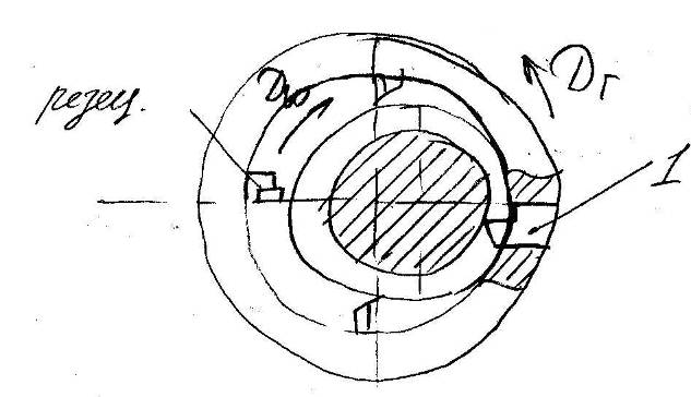
Rice. 1.11. – Thread cutting pattern with a female head.
1.2.4.3. Threading with dies and self-expanding heads
When threading on turret lathes and modular machines, dies can be used as a tool. The die holders allow the tool to move freely a small amount, or, as they say, self-align in the longitudinal direction. This eliminates thread breakage when the speed of movement of the die holder along the workpiece axis and the speed of screwing the die onto the workpiece do not match.The main disadvantage of the dies is the need to screw them together after threading is completed, which reduces productivity and quality of processing.
When machining with self-opening cutting heads, make-up is not required and productivity is greatly increased.
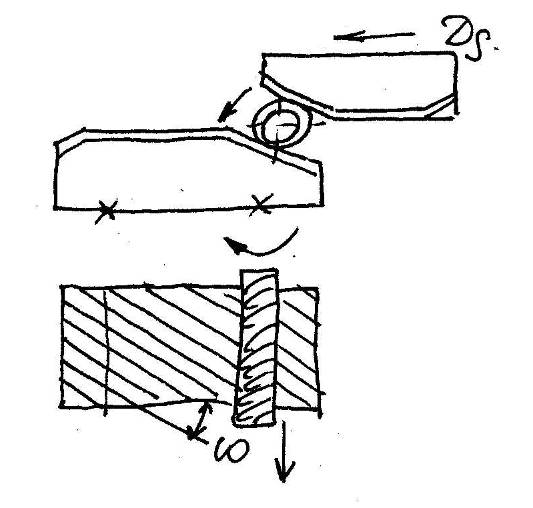
1.2.4.4. Thread milling with disc and comb (group) cutters
Milling with disk cutters (Fig. 1.12.) Is used for processing large threads with sufficiently large output volumes. In this case, processing is performed in 1-3 working steps. The workpiece slowly rotates, and the cutter rotating at the speed of the main movement moves along its axis with a feed per revolution equal to the thread pitch.
Rice. 1.12. – Thread milling scheme.
Compared to turning, the advantage of milling is higher productivity, the possibility of multi-machine maintenance and the use of a low-skilled worker.
Milling with comb (group) cutters is used to obtain short external and internal threads with fine pitch.
In contrast to the processing of threads with a disk cutter, the axes of the comb cutter and the workpiece are parallel (Fig. 1.13.). The length of the cutter is usually 2-3 steps longer than the length of the threaded section of the workpiece.

Rice. 1.13. – Scheme of thread milling with a comb cutter.
At the start of machining, the rotary cutter moves in the radial direction  and plunges into the workpiece to the depth of the thread profile. In this case, for 1 revolution of the workpiece, the cutter moves along the axis by a thread pitch (feed motion
  ). Milling takes place in 1.2 revolutions of the workpiece. Moreover, at the beginning of processing, 0.2 revolutions are necessary for cutting the cutter, and at the end - for cleaning the traces of cutting.
1.2.4.5. Thread rolling
Thread rolling is used in large-scale and mass production. In addition to high productivity, the method makes it possible to obtain a favorable hardened surface structure of the metal, since the fibers of the material are plastically deformed and not cut.The thread is rolled with flat dies or rolling rollers.
On flat dies (Fig. 1.14.) There is a straight thread (thread development) with the same profile and lead angle  as with rolled threads. The thread is rolled in one double stroke of the slider. The number of double strokes per minute reaches 280.
Rice. 1.14. – Scheme of thread rolling with dies.
Thread rolling with one roller is used on lathes, turrets and automatic machines due to one-sided radial force. In this case, bending of the workpiece is possible.
Therefore, thread rolling with two rollers with a radial feed movement has become more widespread (Fig. 1.15.).
Thread rolling can also be carried out with two or four rollers with longitudinal feed at a constant center distance. In terms of productivity, rolling with rollers is usually inferior to rolling with dies.

Rice. 1.15. - Scheme of thread rolling with rollers.
With very rare exceptions, the processing of all types of shafts is built using center machines, and in this case the technology consists of the following operations: cutting off workpieces, cutting ends and centering, then turning operations are performed on center lathes, most often on multi-cutting machines of a standard type, after When turning a workpiece, a grooving operation is performed, and then all grinding operations, keyway milling is most often performed before shaft grinding operations.
After the completion of all machining of the shafts it is necessary to carry out bench cleaning of the key grooves, due to their distortion in width after grinding due to tightening of the edges. Therefore, some factories prefer to mill keyways, especially if they are grooving semi-circular keys after grinding the shaft. In this case, due to some raising of the edges, it is also necessary to perform a manual cleaning operation, i.e. chamfering, however, this operation is less laborious than in the first case, in addition, the risk of damage to the shaft during cleaning is reduced.
All shaft turning is done, as a rule, in two installations on multi-cutting lathes, turning part of the shaft for each installation. In addition, depending on the design of the shaft and the condition of the equipment, sometimes the shaft is also finished turning and several short turning operations that are in the nature of finishing, including trimming the ends of the undercut fillets, grooves, etc.
Grooving operation often made on a conventional lathe, using one or two knurling rollers, mounted in a special holder. The rollers roll in longitudinal feed while being pressed against the shaft to such an extent that a full profile corrugation is formed in one pass.
Grinding operations are produced on conventional center round grinding machines. Most surfaces are ground with a longitudinal movement of the product in relation to the circle, and only in some cases is a more efficient method of grinding in wide circles, in accordance with the width of the surface to be treated, with transverse feeds used.
Keyway milling produced on simple horizontal milling machines. In the manufacture of keyways, small hand tools are used with great success. milling machines with lever control. Despite their simplicity and primitiveness, such milling machines turn out to be very convenient and highly productive for such short-term operations.
In the manufacture of long and thin shafts, a dressing operation is introduced before grinding, either on manually or mechanically driven presses, or on small hydraulic or pneumatic presses. Control of all dimensions in the production process is carried out with the help of rigid limit gauges and templates. With the exception of runout checks and dressing operations, indicator devices are almost never used.
The disadvantages of the described technology are reduced mainly to the following:
1) the equipment and manufacturing methods used are of low productivity and lagged behind modern methods of mass production;
2) in most cases, steel in the form of black non-calibrated bars is used as the starting material, which leads to the need to also machine the middle part of the shaft, which has largest diameter. This circumstance alone, increasing the complexity of processing, leads to material losses, at least 15-20%;
3) the operations of cutting off the workpiece, turning the ends and drilling the centers are carried out on conventional equipment designed to work in mass production and therefore have low productivity, with a relatively large proportion of manual auxiliary time. So, for example, drilling of centers is most often performed on vertical drilling machines in two transitions, i.e. each side of the shaft independently, turning the shaft;
4) turning operations are also performed on insufficiently productive universal-purpose equipment. A special disadvantage of the multi-cutting machines used is their low adaptability to a quick change of setting from one shaft size to another, which leads to large losses of time during changeovers. Particular attention should be paid to the method used for the production of corrugation. At existing way When rolling on lathes of pre-turned shafts, it is impossible to maintain the dimensions of diameters accurately enough and avoid unacceptable fluctuations in dimensions and deviations from the required straightness of the corrugation. The latter is required for proper fit rotor core (armature). Finally, the practiced method of grinding in narrow circles with longitudinal feed is inefficient. It should be noted that, as a rule, even where it is quite possible and rational, as, for example, when grinding necks, machines are not equipped with devices for measuring the dimensions being ground during operation, i.e., on the move of the machine, but for checking the dimensions the machine stops.
It should be noted that the cleaning and washing of the shaft during processing, in particular before final grinding, and in finished form is not provided for in the current technology. This is how the most common shaft centering process looks like.
There is, however, a completely different process for centerless shaft machining., which has a number of advantages compared to the center method and leads to a significant reduction in the complexity of processing. This process is used with great success in the manufacture of shafts in the production of automotive and tractor electrical equipment.
With the centerless method, the source material must necessarily be a calibrated and carefully straightened bar. The first operation - the complete turning of the shaft is carried out on a bar machine. In order to avoid bending the long shafts during turning, the latter are supported by roller steady rests. In subsequent shaft processing operations, preliminary grinding is carried out on centerless grinding machines, and the first operations are performed with a through feed of products, on two or three consecutive machines.
In the future, corrugation is rolled. This operation in the production of automotive and tractor electrical equipment was carried out differently from how it is done at other electrical engineering plants. To ensure the correct dimensions of the diameters and to maintain the same strength of the pressing of various shafts, the latter, before rolling, were necessarily ground along their diameter, while the dimensions were maintained according to the third accuracy class. The rolling operation is carried out on a powerful horizontal type thread rolling machine. In addition to the very high productivity of this rolling method, a complete straightness of the corrugation is also ensured, which is absolutely necessary in some machine designs.
Indeed, if the rotor core is pressed onto a corrugated shaft, then its individual sheets in the process of pressing inevitably tend to follow the shape and direction of the corrugation. Therefore, if the corrugations have at least very slight curvatures and go in a steep spiral, then all the grooves of the core must repeat the curvature of the corrugations.
It is known that distortions in the form of grooves are completely unacceptable, especially with machine winding of the armature. You should not think that if the anchor electrical machine must have oblique grooves, then the corrugation may have a corresponding slope. In fact, for all designs of armatures and rotors without exception, the corrugation should be as straight as possible, and the necessary bevel of the grooves is obtained in the pressing process using appropriate inclined guide knives in the pressing device.
Often the lack of the ability to manufacture shafts with absolutely straight corrugations at the factory forces one to use other, much more expensive methods of fixing the core on the shaft and, in particular, to use keys for this purpose.
For corrugated shafts it is not necessary to use machines with flat dies and progressive stroke, but other types of thread rolling equipment can be successfully used. After knurling, the shafts undergo grinding operations on centerless grinders, partly with longitudinal, but mainly with transverse feed.
At the same time, the outer diameter of the corrugated surface is also necessarily ground in order to maintain the size within the third accuracy class and somewhat dull the tops of individual teeth, thereby ensuring the same amount of tension and high quality of the press connection.
Centerless machining requires fewer operations than center machining, and, in particular, all procurement operations are eliminated - cutting off the workpiece, turning its ends and centering. The equipment used in this case also has a higher productivity. A bar-turning machine for shaft turning requires less maintenance from the worker than a multi-cutting lathe. The quality of the shafts obtained by both methods is approximately the same. With centerless machining of shafts having several ledges along their length, the values of their beats can be maintained within the required tolerances.
You may also be interested in:


How to understand: will the kitten be fluffy?
What kind of light alcohol can be drunk for pregnant women: the consequences of drinking
Why do the legs swell in the ankles and ankles of the feet in pregnant women: causes and methods of treatment
The wedding of Prince Harry and Meghan Markle: scandalous and secret details of the marriage (photo) The future marriage of Prince Harry year NTV
How to close white plums for the winter