GOST 8724-(ISO 261
INTERSTATE STAND
THREAD METRIC
Diameters and steps
Official edition
INTERSTATE COUNCIL FOR STANDARDIZATION, METROLOGY AND CERTIFICATION
MKS 21.040.10 Group G13
to GOST 8724-2004 (ISO 261-98) Basic standards of interchangeability. The thread is metric. Diameters and steps
(IUS No. 10 2004)
Foreword
1 DEVELOPED by the Scientific Research and Design Institute of Measuring Instruments in Mechanical Engineering (OJSC NIIizmereniya)
2 INTRODUCED by the State Standard of Russia
3 ADOPTED by the Interstate Council for Standardization, Metrology and Certification (Minutes No. 22 of November 6, 2002)
4 This International Standard is an identical text international standard ISO 261-98 ISO general purpose threads. Diameters and steps in the range of diameters from 1 to 300 mm” and contains additional requirements reflecting the needs of the country’s economy
5 Decree of the State Committee Russian Federation on standardization and metrology dated June 23, 2003 No. ° 201-st, the interstate standard GOST 8724-2002 (ISO 261-98) was put into effect directly as the state standard of the Russian Federation from January 1, 2004.
6 INSTEAD OF GOST 8724-81
© IPK Standards Publishing House, 2003
This standard cannot be fully or partially reproduced, replicated and distributed as an official publication on the territory of the Russian Federation without the permission of the State Standard of Russia
1 area of use............................................... ......... one
3 Definitions................................................... .............. one
4 Choice of diameters and pitches............................................... ....... one
5 Thread designations .................................................................. ......... 7
GOST 8724-2002 (ISO 261-98)
INTERSTATE STANDARD
Basic norms of interchangeability
THREAD METRIC
Diameters and steps
Basic norms of interchangeability. Metric screw threads. general plan
Introduction date 2004-01-01
1 area of use
This standard applies to general-purpose metric threads with a profile in accordance with GOST 9150 and establishes their diameters from 0.25 to 600 mm and pitches from 0.075 to 8 mm.
Main dimensions metric thread- according to GOST 24705.
Thread tolerances - according to GOST 9000 and GOST 16093.
Additional requirements reflecting the needs of the country's economy are in italics.
GOST 9000-81 Basic norms of interchangeability. Thread metric for diameters less than 1 mm. Tolerances
GOST 9150-2002 Basic norms of interchangeability. The thread is metric. Profile
GOST 11708-82 Basic norms of interchangeability. Thread. Terms and Definitions
GOST 16093-70 Basic norms of interchangeability. The thread is metric. Tolerances. Landings with clearance
GOST 24705-81 Basic norms of interchangeability. The thread is metric. Main dimensions
3 Definitions
Terms and definitions - according to GOST 11708.
4 Choice of diameters and pitches
4.1 Diameters and pitches of threads must correspond to those indicated in Table 1.
When choosing thread diameters, the first row should be preferred to the second, and the second to the third.
Official edition
| Table 1 |
||||||||||||||||||||||||||||||||||||||||||||||||||||||||||||||||||||||||||||||||||||||||||||||||||||||||||||||||||||||||||||||||||||||||||||||||||||||||||||||||||||||||||||||||||||||||||||||||||||||||||||||||||||||||||||||||||||||||||||||||||||||
| |
||||||||||||||||||||||||||||||||||||||||||||||||||||||||||||||||||||||||||||||||||||||||||||||||||||||||||||||||||||||||||||||||||||||||||||||||||||||||||||||||||||||||||||||||||||||||||||||||||||||||||||||||||||||||||||||||||||||||||||||||||||||
| Nominal thread diameter d = D |
|||||||||||
| Table 1 continued |
|||||||||||||||||||||||||||||||||||||||||||||||||||||||||||||||||||||||||||||||||||||||||||||||||||||||||||||||||||||||||||||||||||||||||||||||||||||||||||||||||||||||||||||||||||||||||||||||||||||||||||||||||||||||||||||||||||||||||||||||||||||||||||||||||||||||||||||||||||||||||||||||||||||||||||||||||||||||||||||||||||||||||||||||||||||||||||
|
|||||||||||||||||||||||||||||||||||||||||||||||||||||||||||||||||||||||||||||||||||||||||||||||||||||||||||||||||||||||||||||||||||||||||||||||||||||||||||||||||||||||||||||||||||||||||||||||||||||||||||||||||||||||||||||||||||||||||||||||||||||||||||||||||||||||||||||||||||||||||||||||||||||||||||||||||||||||||||||||||||||||||||||||||||||||||||
| Nominal thread diameter d = D |
||||||||||
| End of table 1 |
|||||||||||||||||||||||||||||||||||||||||||||||||||||||||||||||||||||||||||||||||||||||||||||||||||||||||||||||||||||||||||||||||||||||||||||||||||||||||||||||||||||||||||||||||||||||||||||||||||||||||||||||||||||||||||||||||||||||||||||||
|
|||||||||||||||||||||||||||||||||||||||||||||||||||||||||||||||||||||||||||||||||||||||||||||||||||||||||||||||||||||||||||||||||||||||||||||||||||||||||||||||||||||||||||||||||||||||||||||||||||||||||||||||||||||||||||||||||||||||||||||||
5 Thread designations
5.1 The symbol for the thread size should include: the letter M, the nominal diameter of the thread and the thread pitch, expressed in millimeters and separated by the sign "x".
Example: M8x1.25
A large step in the thread designation can be omitted.
Example: M8.
5.2 The symbol of the left thread should be supplemented with the letters LH.
Example M8x1 - LH
5.3 A multi-start thread should be designated by the letter M, the nominal thread diameter, the sign x, the letters Ph, the value of the thread lead, the letter P and the pitch value.
An example of a symbol for a two-start thread with a nominal diameter of 16 mm, a stroke of 3 mm and a pitch of 1.5 mm:
The same for the left thread:
M16xPMP1.5 - LH
For greater clarity, the text may indicate the number of thread starts in brackets.
Example: M16xPM1.5 (two passes)
5.4 The complete thread designation includes the size designation and thread tolerance fields in accordance with GOST 9000 or GOST 16093.
UDC 621.882.082.1:006.354 MKS 21.040.10 G13 OKSTU 0071
Keywords: thread, metric thread, diameters, steps, conventions
Editor R.G. Goverdovskaya Technical editor V.N. Prusakova Proofreader M.S. Kabashova Computer layout S.V. Ryabovoy
Ed. persons. No. 02354 dated 07/14/2000. Handed over to the set 12.08.2003. Signed for publication on 15.09.2003. Conditions.print.l. 1.40. Uch.-ed.l. 0.65.
Circulation 1150 copies. From 11890.3ac.786.
IPK Standards Publishing House, 107076 Moscow, Kolodezny per., 14. http://www.standards.ru e-mail: [email protected]
Typed in the Publishing House on a PC Branch of the IPK Publishing House of Standards - type. Moscow Printer, 105062 Moscow, Lyalin per., 6.
Table of thread hole diameters
Thread is a helical groove of constant cross section, made on the external (external thread) and internal (internal thread) cylindrical or conical surface. It is used to connect parts, as well as to convert rotational motion into translational or vice versa, in mechanisms and machines.
Threads there are single-start, formed by one helical line (thread), or multi-start, formed by two or more lines.
In the direction of the helix carvings divided into right and left.
Depending on the size system carvings There are metric, inch, pipe.
Metric carving the angle of the triangular profile is 60°, outer, middle and inner diameter s and step carvings expressed in millimeters. Coarse pitch metric threads are designated by a letter and a number expressing outside diameter in millimeters: M10, M16 and so on. To designate carvings with a small pitch (distance between turns), a number is added to this data expressing the pitch carvings in millimeters: M6×0.6, M20×1.5 and the like.
In inch carving the angle of the triangular profile is 55°, the thread diameter is expressed in inches (1 inch = 2.54 cm), and the pitch is the number of threads per inch.
Designation Example: 1 1/4″ (O.D. carvings in inches).
Trubnaya thread differs from the inch in that its initial size is not the outer diameter, but the diameter of the pipe opening, on outer surface which is cut thread.
Designation example: 3/4″ pipes. (numbers indicate the internal diameter of the pipe in inches).
Cutting carvings is carried out on drilling, turning and special thread-cutting (profile-rolling) machines, as well as manually. When manually processing metals, the internal carving cut with taps, and the outer - with dies.
Accordingly, depending on the profile of the cut carvings taps are divided into three types: for metric, inch and pipe.
Manual (locksmith) taps are usually made in a set of three or two pieces. First and second taps carving pre-cut, and the third give it the final size and shape. Usually the number of each tap set is marked by the number of scratches on the tail. There are sets consisting of two taps: preliminary (rough) and finishing. First and second. The taps are made from high strength carbon and alloy steel.
Dies or faceplates intended for cutting the outer carvings, depending on the design are divided into round and prismatic (sliding).
Round dies during threading are fixed in a special knob - a die holder.
Internal thread cutting
For cutting the inner carvings a hole is first prepared with a tap. The drill is taken with a slightly larger diameter than the inner diameter of the required carvings: if these diameters are equal, then the material extruded during cutting will strongly press on the teeth of the tool. As a result, the teeth will heat up and metal particles will stick to them, thread it will turn out with torn scallops (threads), while the tap may break.
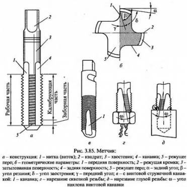
The figure shows the cutting of the inner carvings:
a - tap, b - cutting carvings.
Tap design
1 - intake part;
2 - calibrating part;
3 - chip groove;
4 - shank;
5 - square.
The following figure shows the cutting of the outer carvings:
a - round die, b - prismatic (sliding) die, c - cutting carvings.
Basic designations:
d1 - inner diameter carvings bolt.
D2 - average diameter carvings bolt.
D1 - inner diameter carvings nuts.
D2 - average diameter carvings nuts.
P - step carvings.
H1 - profile height.
d resp. - hole diameter for cutting carvings.
In order not to calculate the diameter of the hole under
carving you can use the table.
| Thread diameter in mm | D2 = d2 in mm | D1 = d1 in mm | P in mm | H1 in mm | d resp. in mm |
| 1 | 0,838 | 0,73 | 0,25 | 0,135 | 0,75 |
| 1,1 | 0,938 | 0,83 | 0,25 | 0,135 | 0,85 |
| 1,2 | 1,038 | 0,93 | 0,25 | 0,135 | 0,95 |
| 1,4 | 1,205 | 1,075 | 0,3 | 0,162 | 1,1 |
| 1,6 | 1,373 | 1,221 | 0,35 | 0,189 | 1,25 |
| 1,8 | 1,573 | 1,421 | 0,35 | 0,189 | 1,45 |
| 2 | 1,74 | 1,567 | 0,4 | 0,216 | 1,6 |
| 2,2 | 1,908 | 1,713 | 0,45 | 0,243 | 1,75 |
| 2,5 | 2,208 | 2,013 | 0,45 | 0,243 | 2,05 |
| 3 | 2,675 | 2,459 | 0,5 | 0,27 | 2,5 |
| 3,5 | 3,11 | 2,85 | 0,6 | 0,325 | 2,9 |
| 4 | 3,546 | 3,242 | 0,7 | 0,379 | 3,3 |
| 4,5 | 4,013 | 3,688 | 0,75 | 0,406 | 3,7 |
| 5 | 4,48 | 4,134 | 0,8 | 0,433 | 4,2 |
| 6 | 5,35 | 4,918 | 1 | 0,541 | 4,95 |
| 7 | 6,35 | 5,918 | 1 | 0,541 | 5,95 |
| 8 | 7,188 | 6,647 | 1,25 | 0,676 | 6,7 |
| 9 | 8,188 | 7,647 | 1,25 | 0,676 | 7,7 |
| 10 | 9,026 | 8,376 | 1,5 | 0,812 | 8,43 |
| 11 | 10,026 | 9,376 | 1,5 | 0,812 | 9,43 |
| 12 | 10,863 | 10,106 | 1,75 | 0,947 | 10,2 |
| 14 | 12,701 | 11,835 | 2 | 1,082 | 11,9 |
| 16 | 14,701 | 13,835 | 2 | 1,082 | 13,9 |
| 18 | 16,376 | 15,294 | 2,5 | 1,353 | 15,35 |
| 20 | 18,376 | 17,294 | 2,5 | 1,353 | 17,35 |
| 22 | 20,376 | 19,294 | 2,5 | 1,353 | 19,35 |
| 24 | 22,051 | 20,752 | 3 | 1,624 | 20,85 |
| 27 | 25,051 | 23,752 | 3 | 1,624 | 23,85 |
| 30 | 27,727 | 26,211 | 3,5 | 1,894 | 26,3 |
| 33 | 30,727 | 29,211 | 3,5 | 1,894 | 29,3 |
| 36 | 33,402 | 31,67 | 4 | 2,165 | 31,8 |
| 39 | 36,402 | 34,67 | 4 | 2,165 | 34,8 |
| 42 | 39,077 | 37,129 | 4,5 | 2,435 | 37,25 |
| 45 | 42,077 | 40,129 | 4,5 | 2,435 | 40,25 |
| 48 | 44,752 | 42,587 | 5 | 2,706 | 42,7 |
| 52 | 48,752 | 46,587 | 5 | 2,706 | 46,7 |
| 56 | 52,428 | 50,046 | 5,5 | 2,977 | 50,2 |
| 60 | 56,428 | 54,046 | 5,5 | 2,977 | 54,2 |
| 64 | 60,103 | 57,505 | 6 | 3,247 | 57,7 |
| 68 | 64,103 | 61,505 | 6 | 3,247 | 61,7 |
Dimensions and a table of values for metric threads allow you to perform high-quality cutting without resorting to complex mathematical calculations. The table provides the necessary information regarding the diameter of the holes, the pitch used, the drill, etc. All parameters are standardized, which allows you to get a high-quality and reliable threaded connection with your own hands.
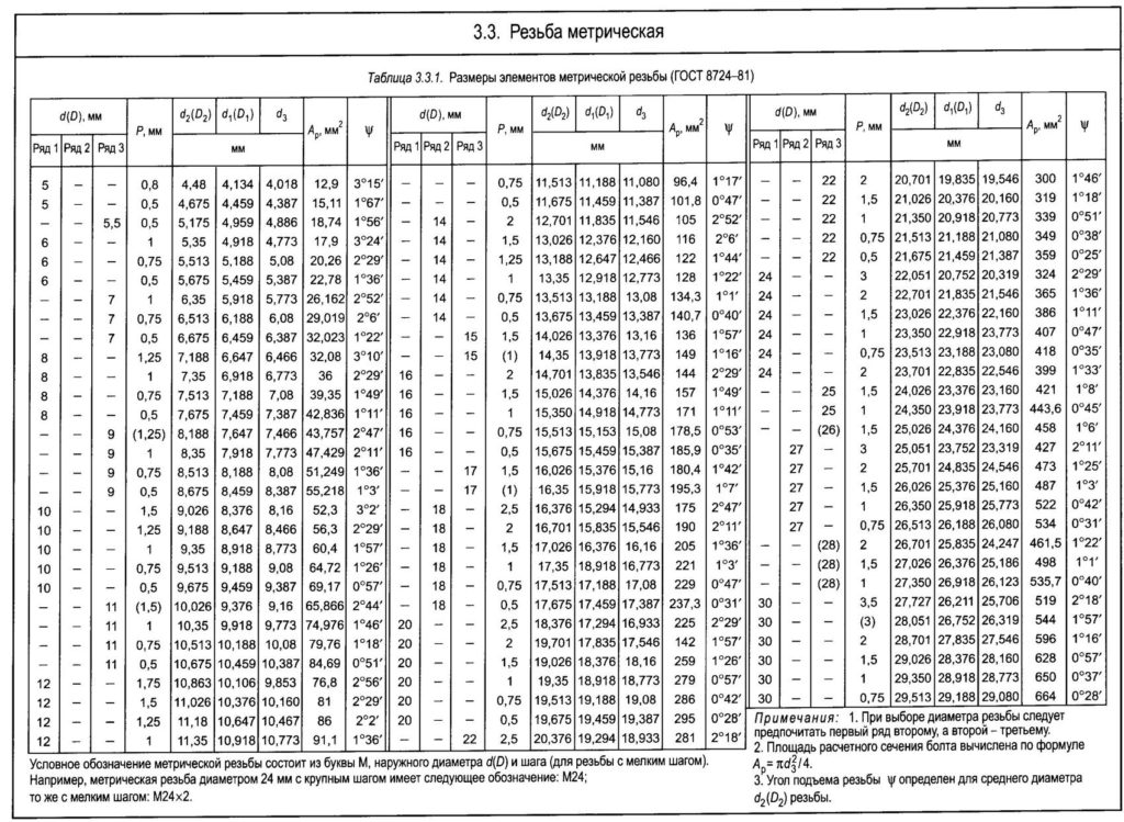
Photo table metric thread
- The vast majority of fasteners are based on metric threads in our country;
- The angle of the triangular profile of the metric thread is 60 degrees;
- All dimensions are in millimeters;
- Metric type cutting is divided into coarse and fine pitch products;
- Coarse pitch is relevant for diameters 1-68 mm, and fine pitch - for diameters 1-600 mm;
- Coarse cutting is used in joints that are subjected to impact loads;
- Fine-pitch thread is relevant for thin-walled parts and for making connections tight;
- Fine-pitch cutting is widely used in adjusting and adjusting fasteners. This is due to the fact that with their help it is easy to adjust the parameters with high accuracy;
- All modern machines are designed on the basis of the use of only metric threads.
Characteristics and designations
Photo table of basic sizes
There are metric, inch, pipe cutting. Each of them is classified according to several criteria:
- The direction of the turns is left and right;
- Profile shape - round, persistent, triangular, etc.;
- Location - external, internal;
- The nature of the surface and function - inch, metric, conical, etc.;
- The number of visits - single-pass and multi-pass.
At the same time, inch and pipe cutting is not as common as metric. In this regard, leaving inch and pipe threads, and consider the metric one in more detail.
The thread has two main characteristics.
- Nominal diameter. They call the conditional dimensions used in the notation. The nominal diameter is equal to the outer diameter of the nut and bolt, which are equal to each other.
- Thread pitch. The dimensions of the thread pitch are equal to the distance between two identical points of the nearest profiles, which are located in the same plane. The definition is rather complicated, but in practice it is very easy to find these dimensions. To determine the dimensions, you need to roll the bolt on a sheet of high-density paper at its core and measure what pitch there is between the nearest located grooves. This is the step. Determining similar dimensions in this way is not a highly accurate method. But to make sure that the dimensions are calculated correctly, there is a special table. This table allows you to check your calculations or determine the required parameters without resorting to measurements or mathematical calculations.
Inch, pipe and our metric threads have specific designations for sizes and other parameters. So that the table does not cause a lot of unnecessary questions, we will try to talk about all the nuances of the designations presented in it.
Letters and numbers are used to designate threads. As an example, thread M40. Here:
- The letter M means the type of cutting. M - metric. It is not inch, pipe. Everything is very clear here;
- 40 are nominal diameters. The number after the letter means what nominal diameters the thread is characterized by. In our case, this is 40 mm;
- If the thread pitch is large, this is not displayed in the designation in any way. You can determine it according to GOST.
As an alternative, consider an example with a small step - M30x2.
- Here the situation is similar with diameters - this figure is 30;
- The cut is metric, as the letter M tells us;
- 2 means the pitch is 2 millimeters.
And a couple more important points.
- The thread can have different pitches and be left-handed or right-handed.
- The right-hand thread is not indicated in the designations.
- If you see something like an M20 LH, that's a left hand thread.
- Number of visits. For a single-start thread, the number is not indicated, since it is always 1. If this is a multi-start thread, then the designation looks something like this - M30x3 (P2). Here, the thread pitch is marked in brackets, and 2 is the number of entries.
Tap selection
The tap is the main working tool with which internal thread future threaded connections. Because to do different kinds threads with a certain pitch, you will need to correctly select a tap to complete the tasks.
- First of all, the master must select the type of tap that is suitable for the planned carving. In our case, we are talking about taps for metric cutting;
- Further, the purpose is determined - step, tolerances, profile shape;
- Depending on the accuracy class, the master decides whether it is possible to get by with one tap, or to complete the operation, you need to acquire a set - a rough and finish tap;
- The material to be cut. The main material for carving is metal. At the same time, it can be different in terms of strength, on which the choice of characteristics of the tap directly depends;
- Front angle of sharpening teeth. For each type of metal there is a specific value. If it is steel, the angle is 5 to 10 degrees, for copper, 0 to 5 degrees, and in the case of aluminum, 25 to 30 degrees;
- Taps can be made of ordinary, high-strength steel or ordinary metal, but with increased strength brazing. Last option makes it possible to reduce the cost of production of taps, but maintain their high reliability;
- The main point in choosing a tap is the diameter of the hole. It is on it that the cutting will be carried out internal thread;
- In this case, the diameter of the tool must be slightly smaller than the diameter of the hole. If you require a metric thread type M20, i.e. the tap diameter is 20 mm, then the hole diameter will be 19 mm. All required parameters are determined by a special standardized table;
- If the thread does not impose special requirements, the standard pitch indicated in the table is used.
The nuances of cutting
When the diameters and other parameters of the required thread were determined and the tap itself was selected, the cutting operation should be performed.
- The workpiece on which cutting is performed is fixed in a vice.
- The axis of the hole should be positioned as perpendicular to the desktop as possible.
- The tap is installed in the socket of the collar, in a vertical position it is wound into a chamfer under the hole in the workpiece.
- With two hands, the master holds the knob, pressing the tap to the part and rotating clockwise.
- The tool should be rotated gently, smoothly and evenly, with a little pressure.
- Two full turns are made, after which half a turn is made back, counterclockwise.
- In the process of making a thread, the tool must be cooled. If it is aluminum, kerosene is used, turpentine acts as a coolant for copper, and an emulsion for steel products. Cast iron and bronze do not need cooling.
- The internal thread is made with a set of taps.
- First, the draft tool is used, then the middle one, and the finishing one completes the work. By eliminating one of the taps, you will not speed up the cutting process, but the thread itself will turn out to be much worse in quality.
It is not difficult to perform metric cutting if you use the appropriate tools and rely on standardized parameters of specialized tables.


How to understand: will the kitten be fluffy?
What kind of light alcohol can be drunk for pregnant women: the consequences of drinking
Why do the legs swell in the ankles and ankles of the feet in pregnant women: causes and methods of treatment
The wedding of Prince Harry and Meghan Markle: scandalous and secret details of the marriage (photo) The future marriage of Prince Harry year NTV
How to close white plums for the winter