GOST 6211-81
Group G13
INTERSTATE STANDARD
Basic norms of interchangeability
THREAD PIPE CONICAL
Basic norms of interchangeability. pipe taper thread
Introduction date 1983-01-01
1. DEVELOPED AND INTRODUCED by the Ministry of Machine Tool and Tool Industry
2. APPROVED AND INTRODUCED BY Decree of the USSR State Committee for Standards dated December 30, 1981 N 5789
3. REPLACE GOST 6211-69
4. The standard fully complies with ST SEV 1159-78
5. REFERENCE REGULATIONS AND TECHNICAL DOCUMENTS
Item number |
|
Introduction, 1.2, 3.3, 4.2 |
6. RE-ISSUE
This standard applies to conical pipe threads with a taper of 1:16, used in conical threaded connections, as well as in connections of external tapered threads with internal cylindrical threads with a profile according to GOST 6357 and establishes the profile, main dimensions and tolerances of the conical thread, as well as the tolerances of the internal cylindrical pipe thread connected to an external conical thread.
1. PROFILE
1. PROFILE
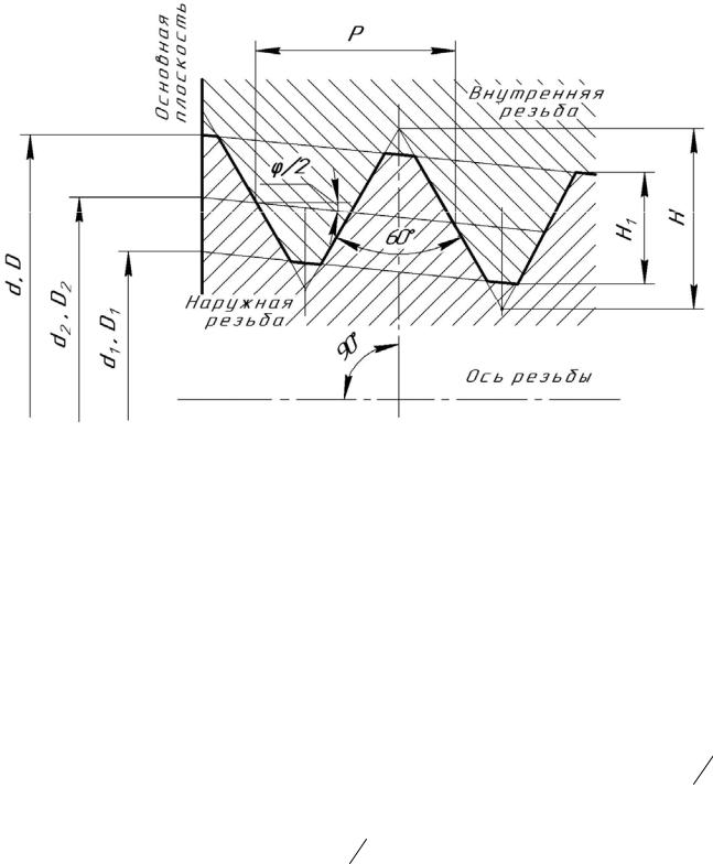
1.1. The nominal profile of the pipe taper thread (external and internal) and the dimensions of its elements must correspond to those indicated in Fig. 1 and in Table 1.
Damn.1. Nominal profile of taper pipe thread (external and internal) and dimensions of its elements
Taper ; ; ; - outside diameter external conical thread; - inner diameter external conical thread; - the average diameter of the external conical thread; - outer diameter of the internal conical thread; - internal diameter of the internal conical thread; - the average diameter of the internal conical thread; - thread pitch; - cone angle; - slope angle; - the height of the original triangle; - working height of the profile; - the radius of rounding of the top and bottom of the thread; - cut tops and bottoms of the thread.
Table 1
Dimensions in mm
Number of steps per 25.4 mm length | |||||
Note. Numeric values steps are determined from the ratio with rounding up to the third decimal place and are taken as initial when calculating the main profile elements.
1.2. The dimensions of the profile elements of the internal cylindrical thread are in accordance with GOST 6357.
2. BASIC DIMENSIONS
2.1. The designation of the thread size, steps and nominal values of the main dimensions of the conical (external and internal) threads must correspond to those indicated in Fig. 2 and in Table 2.
Damn.2. Thread size designation, pitches and nominal values of the main dimensions of the conical (external and internal) threads
Working thread length; - length external thread from the end to the main plane
table 2
Dimensions in mm
Designation | Thread diameters in the base plane | Thread length |
||||
It is allowed to use more short lengths threads
2.2. Numerical values of diameters and are calculated by the following formulas
The numerical values of the diameter are established empirically.
2.3. The difference in actual dimensions must not be less than the difference in nominal dimensions and specified in Table 2.
2.4. The length of the internal tapered thread must be at least 0.8 (, where - in accordance with Table 3) *.
________________
* The text of the document corresponds to the original. - Database manufacturer's note.
Table 3
Dimensions in mm
Thread size designation | Offset thread base plane | Limit deviations of the diameter of the internal cylindrical thread |
|
2; 3; 3; 4; 5; 6 | |||
Note. Limit deviations and do not apply to threads with lengths less than those indicated in Table 2.
2.5. The designation of thread sizes, pitches and nominal values of the outer, middle and inner diameters of the internal cylindrical thread must correspond to those indicated in Fig. 3 and in Table 2.
Damn.3. Designation of thread sizes, pitches and nominal values of the outer, middle and inner diameters of the internal cylindrical thread
2.6. The design of parts with internal threads (conical and cylindrical) must ensure that the external conical thread is screwed in to a depth of at least .
3. TOLERANCES
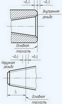
3.1. The axial displacement of the main plane of the external and internal threads (Fig. 4) relative to the nominal location should not exceed the values \u200b\u200bspecified in Table 3.
Damn.4. Axial displacement of the main plane of external and internal threads
Note. In the main plane, the average diameter has a nominal value.
The displacement of the main plane is total, including deviations of the average diameter, pitch, angle of inclination of the side of the profile and the angle of the cone.
3.2. Limit deviations of the average diameter of the internal cylindrical thread must correspond to those indicated in Table 3.
3.3. It is allowed to connect an external conical thread with an internal cylindrical thread of accuracy class A according to GOST 6357.
4. NOTATION
4.1. The thread symbol should include: letters ( - for a conical external thread, - for a conical internal thread, - for a cylindrical internal thread) and thread size designation.
The symbol for the left thread is supplemented with letters.
Thread convention examples:
- external pipe conical thread 1:
Female pipe taper thread 1:
Female cylindrical thread 1:
Left hand thread:
4.2. A threaded connection is indicated by a fraction, for example, or, in the numerator of which the letter designation of the internal thread is indicated, and in the denominator - the external thread, and the size of the thread.
Examples of symbols for threaded connections:
- pipe conical thread (internal and external):
Female straight pipe threads (to the tolerances of this International Standard) and male taper pipe threads:
Internal cylindrical pipe thread of accuracy class A according to GOST 6357 and external pipe conical thread:
APPENDIX (reference). MAXIMUM DEVIATIONS OF INDIVIDUAL THREAD PARAMETERS
APPENDIX
Reference
1. This appendix contains information on the limit deviations of individual thread parameters, which are initial in the design of a thread-forming tool and the calculation of thread gauges and are not subject to mandatory control, unless otherwise stated.
2. Limit deviations of the cut of peaks and troughs (size), angle of inclination of the side of the profile, pitch and angle of the cone (difference in average diameters along the length) of the conical thread are shown in Fig. 1 and in the table.
Damn.1. Limit deviations of the cut of peaks and troughs, the angle of inclination of the lateral side of the profile, the pitch and the angle of the cone
es - upper deviation of the cut of the top and bottom of the external thread; ES - upper deviation of the cut of the top and bottom of the internal thread; ei - lower deviation of the cut of the top and bottom of the external thread; EI - lower deviation of the cut of the top and bottom of the internal thread; - tolerance of the angle of inclination of the side of the thread profile.
3. Limit deviations of the cut of peaks and troughs (size) of an internal cylindrical thread (Fig. 2) should not exceed:
- top cut +0.05 mm (ES=+0.05 mm, EI=0);
- recess cut ±0.025 mm (ES=+0.025 mm, EI=-0.025 mm)
Damn.2. Limit deviations of the cut of peaks and troughs of an internal cylindrical thread
Dimensions in mm
Thread size designation | Previous off | Difference of average diameters |
||||||||
steps in length | ||||||||||
peaks | hollows | Previous off |
||||||||
external thread | internal thread |
|||||||||
0,028 | 0,014 |
|||||||||
0,042 | 0,021 |
|||||||||
0,044 | 0,022 |
|||||||||
0,058 | 0,028 |
|||||||||
0,066 | 0,034 |
|||||||||
0,073 | 0,036 |
|||||||||
0,089 | 0,045 |
|||||||||
0,111 | 0,056 |
|||||||||
0,122 | 0,062 |
|||||||||
0,073 |
||||||||||
0,155 | 0,078 |
|||||||||
0,177 | 0,089 |
|||||||||
0,200 | 0,101 |
|||||||||
Note. The value refers to the distance between the threads. The actual deviation can be minus or plus sign.
Electronic text of the document
prepared by Kodeks JSC and verified against:
official publication
Inch and special threads: Sat. GOSTs. -
M.: IPK Standards Publishing House, 2003
BASIC DIMENSIONS
PIPE CONICAL THREAD
(GOST 6211-81)
This standard applies to taper pipe threads with taper 1: 16 . used in conical threaded connections, as well as in connections of external tapered thread with an internal cylindrical thread with a profile according to GOST 6357-81.
Taper 2tg(φ /2) = 1: 16;
φ = 3°34"48"; φ/2 = 1°47"24";
d and D are the outer diameters of the external and internal threads, respectively;
d 1 and D 1 are the internal diameters of the external and internal threads, respectively;
d 2 and D 2 are the average diameters of the external and internal threads, respectively;
P - thread pitch;
φ - cone angle; φ/2 - slope angle;
H is the height of the original triangle;
H 1 - working height of the profile;
R is the radius of rounding of the top and bottom of the thread;
C - cut tops and bottoms of the thread;
l 1- working thread length;
l 2- the length of the external thread from the end to the main plane.
dimensions, mm
| Thread size designation | Step P | Number of steps per length 25.4mm | H | H1 | C | R | Thread diameters in the base plane | Thread length | |||
| d=D | d2 = D2 | d1 = D1 | l 1 | l 2 | |||||||
| 1/16" | 0,907 | 28 | 0,870935 | 0,580777 | 0,145079 | 0,124511 | 7,723 | 7,142 | 6,561 | 6,5 | 4,0 |
| 1/8" | 9,728 | 9,147 | 8,566 | ||||||||
| 1/4" | 1,337 | 19 | 1,283837 | 0,856117 | 0,213860 | 0,183541 | 13,157 | 12,301 | 11,445 | 9,7 | 6,0 |
| 3/8" | 16,662 | 15,806 | 14,950 | 10,1 | 6,4 | ||||||
| 1/2" | 1,814 | 14 | 1,741870 | 1,161553 | 0,290158 | 0,249022 | 20,955 | 19,793 | 18,631 | 13,2 | 8,2 |
| 3/4" | 26,441 | 25,279 | 24,117 | 14,5 | 9,5 | ||||||
| 1" | 2,309 | 11 | 2,217187 | 1,478515 | 0,369336 | 0,316975 | 33,249 | 31,770 | 30,291 | 16,8 | 10,4 |
| 1 1/4" | 41,910 | 40,431 | 38,952 | 19,1 | 12,7 | ||||||
| 1 1/2" | 47,803 | 46,324 | 44,845 | ||||||||
| 2" | 59,614 | 58,135 | 56,656 | 23,4 | 15,9 | ||||||
| 2 1/2" | 75,184 | 73,705 | 72,226 | 26,7 | 17,5 | ||||||
| 3" | 87,884 | 86,405 | 84,926 | 29,8 | 20,6 | ||||||
| 3 1/2" | 100,330 | 98,851 | 97,372 | 31,4 | 22,2 | ||||||
| 4" | 113,030 | 111,551 | 110,072 | 35,8 | 25,4 | ||||||
| 5" | 138,430 | 136,951 | 135,472 | 40,1 | 28,6 | ||||||
| 6" | 163,830 | 162,351 | 160,872 | ||||||||
SYMBOL
The thread symbol should include: letters (R - for a tapered external thread, R c - for a tapered internal thread, R p - for a cylindrical internal thread) and thread size designation:
external pipe conical thread - R 1 1/2
internal pipe taper thread - R with 1 1/2
female cylindrical thread - R p 1 1/2
left-hand thread - R 1 1/2LH, R c 1 1/2LH, R p 1 1/2LH.
A threaded connection is indicated by a fraction, for example Rc / R or Rp / R, in the numerator of which indicate the letter designation of the internal thread, and in the denominator - the external thread, and the size of the thread.
For instance: R with /R 1 1/4LH.
TAPERED PIPE THREAD TOLERANCES
(GOST 6211-81)
dimensions, mm
| Thread profile | Designation size carving | Offset thread base plane | Limit deviations diameter internal cylindrical carving |
|
| ±Δ 1 l 1 | ±Δ 2 l 2 | |||
 | 1/16" | 0,9 | 1,1 | ±0.071 |
| 1/8" | ||||
| 1/4" | 1,3 | 1,7 | ±0.104 | |
| 3/8" | ||||
| 1/2" | 1,8 | 2,3 | ±0.142 | |
| 3/4" | ||||
| 1" | 2,3 | 2,9 | ±0.180 | |
| 1 1/4" | ||||
| 1 1/2" | ||||
| 2" | ||||
| 2 1/2" | 3,5 | 3,5 | ±0.217 | |
| 3" | ||||
| 3 1/2" | ||||
| 4" | ||||
| 5" | ||||
| 6" | ||||
| In the main plane, the average diameter has a nominal value. | ||||
| Note. The limit deviation ±Δ 1 l 1 and ±Δ 2 l 2 does not apply to threads with lengths less than those indicated in the first table. | ||||
Shorter thread lengths may be used.
Actual size difference l 1 - l 2 must be at least the difference in nominal dimensions l 1 and l 2 indicated in the first table.
Related Documents:
GOST 3469-91: Microscopes. Thread for lenses. Dimensions
GOST 4608-81: Metric thread. Interference landings
GOST 5359-77: Ocular thread for optical instruments. Profile and dimensions
GOST 6042-83: Round Edison thread. Profiles, dimensions and limit dimensions
GOST 6111-52: Conical inch thread with a profile angle of 60 degrees
GOST 6211-81: Conical pipe thread
GOST 6357-81: Cylindrical pipe thread
GOST 8762-75: Round thread with a diameter of 40 mm for gas masks and calibers for it. Main dimensions
GOST 9000-81: Metric thread for diameters less than 1 mm. Tolerances
GOST 9484-81: Trapezoidal thread. Profiles
GOST 9562-81: Trapezoidal single thread. Tolerances
GOST 9909-81: Conical thread of valves and cylinders for gases
GOST 10177-82: Thrust thread. Profile and main dimensions
GOST 11708-82: Thread. Terms and Definitions
GOST 11709-81: Metric thread for plastic parts
GOST 13535-87: Reinforced thrust thread 45 degrees
GOST 13536-68: Round thread for sanitary fittings. Profile, basic dimensions, tolerances
GOST 16093-2004: Metric thread. Tolerances. Landings with clearance
GOST 16967-81: Metric thread for instrumentation. Diameters and steps
GOST 24737-81: Trapezoidal single thread. Main dimensions
GOST 24739-81: Multi-start trapezoidal thread
GOST 25096-82: Thrust thread. Tolerances
GOST 25229-82: Metric conical thread
GOST 28487-90: Tapered tool joint thread for drill string elements. Profile. Dimensions. Tolerances
Pipe conical thread is used in conical threaded connections and in connections of external conical thread with internal cylindrical thread. Profiles and main dimensions are established by GOST
6211–81 (Table 4.10).
GOST 6211–81 "Conical pipe thread"
The standard defines the nominal profile of taper pipe threads (external and internal). The dimensions of its elements must correspond to those indicated in Fig. 4.8.
Rice. 4.8. Pipe taper thread profile (GOST 6211–81)
The following designations are accepted in the standard: d is the outer diameter of the
manual conical thread; d 1 - inner diameter of the outer conical thread
would; d 2 - the average diameter of the external tapered thread; D - the external diameter of the internal tapered thread; D 1 - the internal diameter of the internal conical thread;
skai carving; D 2 - the average diameter of the internal conical thread; | P - step |
|
threads; φ – cone angle; | - slope angle; H is the height of the original | triangular |
ka; H 1 - working height of the profile; R - radius of curvature of the top and bottom |
||
threads; C - cut tops and bottoms of the thread; l 1 - working length | threads; l 2 - |
|
external thread length | from the end to the main plane; | taper |
2 tg 2 1:16; φ = 3° 34′ 48″; 2 = 1° 47′ 24″.
The thread has a taper of 1:16.
Table 4.10 |
||||||||
Dimensions of pipe conical thread (GOST 6211–81), mm |
||||||||
Designation | Thread diameters in the main | Thread length | ||||||
P step | plane | |||||||
d=D | d2= D2 | d1= D1 | ||||||
The end of the table. 4.10 |
||||||||
1 1 4 | ||||||||
1 1 2 | ||||||||
2 1 2 | ||||||||
3 1 2 | ||||||||
Designation of pipe conical thread
The thread designation must include letters (R - for tapered external thread, R C - for tapered internal thread, R P - for cylindrical internal thread) and thread size designation. The symbol for the left thread is supplemented by the letters LH.
Thread designation examples:
external pipe conical thread 11/2 inches:
R 1 1 /2 ;
female 11/2" taper pipe thread:
R C1 1 / 2;
female cylindrical thread 11/2 inches:
R P1 1 / 2;

left thread designation:
R 11 /2 LH;
RC 11/2 LH;
RP 11/2 LH.
Threaded connection denoted by a fraction, for example R R C or R C R, in number
the letter of which indicates the letter designation of the internal thread, and in the denominator - the external thread. After the fraction, the thread size is indicated and for the left thread, the letters LH.
Examples of designation of a threaded connection: pipe conical thread (internal and external):
R R C1 1 2 ;
R C 1 1 2 L H.
§ 4.8. Tapered inch thread with 60° profile angle
Threaded inch is used in connection of fuel, oil, water and air pipelines of machines and machine tools. Profile, main dimensions are established by GOST 6111–52 (Table 4.11).
GOST 6111–52 "Conical inch thread with a profile angle of 60°"
The standard applies to threaded connections pipelines of machines and machine tools. Profile and dimensions of conical inch thread with a profile angle of 60° must correspond to fig. 4.9.
Rice. 4.9. Tapered inch thread profile with 60° profile angle
(GOST 6111–52)
Designation of a tapered inch thread with a profile angle of 60°
The designation of a tapered thread must include the letter K and the value of the diameter of the conditional bore in the pipe (in inches).
Example symbol threads with nominal diameter 3 4
K 3 4".
Table 4.11
Dimensions of taper inch thread with a profile angle of 60° (GOST 6111–52)
11 1 /2 | |||
1 1 4 | 11 1 /2 | ||
1 1 2 | 11 1 /2 | ||
11 1 /2 | |||
Thread length, mm | Thread diameter | |||||
in the main plane, mm | ||||||
meter thread | ||||||
basic | pipe head, | |||||
plane | ||||||


How to understand: will the kitten be fluffy?
What kind of light alcohol can be drunk for pregnant women: the consequences of drinking
Why do the legs swell in the ankles and ankles of the feet in pregnant women: causes and methods of treatment
The wedding of Prince Harry and Meghan Markle: scandalous and secret details of the marriage (photo) The future marriage of Prince Harry year NTV
How to close white plums for the winter