In stock!
High performance, convenience, easy operation and reliable operation.
Welding screens and protective curtains - in stock!
Protection against radiation during welding and cutting. Big choice.
Delivery throughout Russia!
General information about cones
The conical surface is characterized by the following parameters (Fig. 4.31): smaller d and larger D diameters and the distance l between the planes in which the circles with diameters D and d are located. Angle a is called the angle of inclination of the cone, and angle 2α is called the angle of the cone.
The ratio K= (D - d)/l is called taper and is usually denoted with a division sign (for example, 1:20 or 1:50), and in some cases - decimal(for example, 0.05 or 0.02).
The ratio Y= (D - d)/(2l) = tgα is called slope.
Methods for processing conical surfaces
When processing shafts, transitions between surfaces that have a conical shape are often encountered. If the length of the cone does not exceed 50 mm, then it can be processed by cutting with a wide cutter. The angle of inclination of the cutting edge of the cutter in the plan must correspond to the angle of inclination of the cone on the machined part. The cutter is given a transverse feed motion.
To reduce the distortion of the generatrix of the conical surface and reduce the deviation of the angle of inclination of the cone, it is necessary to set the cutting edge of the cutter along the axis of rotation of the workpiece.
It should be borne in mind that when machining a cone with a cutter with a cutting edge longer than 15 mm, vibrations may occur, the level of which is the higher, the longer the workpiece is, the smaller its diameter, the smaller the angle of inclination of the cone, the closer the cone is to the middle of the part, the longer the overhang cutter and less strength of its fastening. As a result of vibrations, traces appear on the treated surface and its quality deteriorates. When machining hard parts with a wide cutter, there may be no vibration, but at the same time, the cutter may be displaced under the action of the radial component of the cutting force, which leads to a misconfiguration of the cutter to the required angle of inclination. (Cutter offset depends on the machining mode and feed direction.)
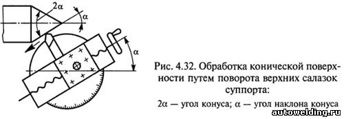
Conical surfaces with large slopes can be processed by turning the upper slide of the caliper with the tool holder (Fig. 4.32) by an angle α equal to the angle of inclination of the cone being machined. The cutter is fed manually (with the handle for moving the upper slide), which is a disadvantage of this method, since the uneven manual feed leads to an increase in the roughness of the machined surface. In this way, conical surfaces are processed, the length of which is commensurate with the stroke length of the upper slide.
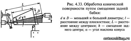
A conical surface of great length with an angle α= 8 ... 10° can be machined when the tailstock is displaced (Fig. 4.33)
At small angles sinα ≈ tgα
h≈L(D-d)/(2l),
where L is the distance between the centers; D - larger diameter; d - smaller diameter; l is the distance between the planes.
If L = l, then h = (D-d)/2.
The displacement of the tailstock is determined by the scale printed on the end face of the base plate from the flywheel side, and the risk on the end face of the tailstock housing. The division value on the scale is usually 1 mm. In the absence of a scale on the base plate, the offset of the tailstock is measured using a ruler attached to the base plate.
To ensure the same conicity of a batch of parts processed in this way, it is necessary that the dimensions of the workpieces and their center holes have slight deviations. Since misalignment of the machine centers causes wear of the center holes of the workpieces, it is recommended to machine the conical surfaces first, then correct the center holes, and then finish finishing. To reduce the breakdown of the center holes and the wear of the centers, it is advisable to carry out the latter with rounded tops.
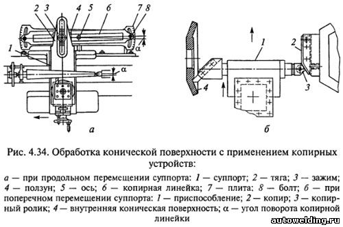
Quite common is the processing of conical surfaces using copiers. A plate 7 is attached to the machine bed (Fig. 4.34, a) with a copy ruler 6, along which the slider 4 moves, connected to the caliper 1 of the machine by a rod 2 using clamp 5. For free movement of the caliper in the transverse direction, it is necessary to disconnect the screw of the transverse feed movement. With the longitudinal movement of the caliper 1, the cutter receives two movements: longitudinal from the caliper and transverse from the copier ruler 6. The transverse movement depends on the angle of rotation of the copier ruler 6 relative to the axis 5 of rotation. The angle of rotation of the ruler is determined by the divisions on the plate 7, fixing the ruler with bolts 8. The movement of the cutter to the cutting depth is performed by the handle for moving the upper caliper slide. The outer conical surfaces are machined with through cutters.
Methods for processing internal conical surfaces
The processing of the inner conical surface 4 of the workpiece (Fig. 4.34, b) is carried out according to the copier 2 installed in the tailstock quill or in the turret of the machine. In the tool holder of the transverse caliper, fixture 1 is installed with a copy roller 3 and a pointed through cutter. With the transverse movement of the support, the cam roller 3, in accordance with the profile of the cam 2, receives a longitudinal movement, which is transmitted to the cutter through the device 1. Internal conical surfaces are machined with boring cutters.
To obtain a conical hole in a solid material, the workpiece is first pre-processed (drilled, bored), and then finally (deployed). The reaming is performed sequentially by a set of conical reamers. The diameter of the pre-drilled hole is 0.5 ... 1 mm less than the lead diameter of the reamer.
If a high-precision conical hole is required, then it is processed with a conical countersink before reaming, for which a hole with a diameter of 0.5 mm less than the diameter of the cone is drilled in a solid material, and then a countersink is used. To reduce the allowance for countersinking, step drills of different diameters are sometimes used.
Center hole machining
In parts such as shafts, center holes are often made, which are used for subsequent turning and grinding of the part and for restoring it during operation. Based on this, the centering is performed especially carefully.
The center holes of the shaft must be on the same axis and have the same conical holes at both ends, regardless of the diameters of the end journals of the shaft. If these requirements are not met, the machining accuracy decreases and the wear of centers and center holes increases.
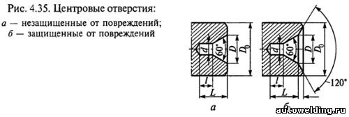
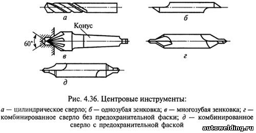
The designs of the center holes are shown in fig. 4.35. Center holes with a cone angle of 60° are the most common. Sometimes in heavy shafts this angle is increased to 75 or 90°. In order for the top of the center not to rest against the workpiece, cylindrical recesses with a diameter d are made in the center holes.
To protect against damage, reusable center holes are made with a safety chamfer at an angle of 120 ° (Fig. 4.35, b).
Various methods are used to machine center holes in small workpieces. The workpiece is fixed in a self-centering chuck, and a drilling chuck with a centering tool is inserted into the tailstock quill. Center holes of large sizes are processed first with a cylindrical drill (Fig. 4.36, a), and then with a single-toothed (Fig. 4.36, b) or multi-toothed (Fig. 4.36, c) countersink. Center holes with a diameter of 1.5 ... 5 mm are processed with combined drills without a safety chamfer (Fig. 4.36, d) and with a safety chamfer (Fig. 4.36, e).
Center holes are processed with a rotating workpiece; the feed movement of the centering tool is carried out manually (from the tailstock flywheel). The end, in which the center hole is processed, is pre-cut with a cutter.
The required size of the center hole is determined by the deepening of the centering tool, using the tailstock flywheel dial or the quill scale. To ensure the alignment of the center holes, the part is pre-marked, and long parts are supported with a steady rest during centering.
Center holes are marked with a square.
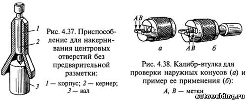
After marking, the center hole is punched. If the diameter of the shaft neck does not exceed 40 mm, then it is possible to punch the center hole without preliminary marking using the device shown in fig. 4.37. The body 1 of the fixture is installed with the left hand on the end of the shaft 3 and the center of the hole is marked with a hammer blow on the center punch 2.
If during operation the conical surfaces of the center holes were damaged or unevenly worn, then they can be corrected with a cutter. In this case, the upper carriage of the caliper is rotated by the angle of the cone.
Control of conical surfaces
The taper of the outer surfaces is measured with a template or a universal goniometer. For more accurate measurements, sleeve gauges are used (Fig. 4.38), with the help of which not only the angle of the cone is checked, but also its diameters. Two or three risks are applied to the machined surface of the cone with a pencil, then a sleeve gauge is put on the measured cone, slightly pressing on it and turning it along the axis. With a correctly executed cone, all risks are erased, and the end of the conical part is between marks A and B.
When measuring conical holes, a plug gauge is used. The correctness of the processing of a conical hole is determined (as in the measurement of external cones) by the mutual contact of the surfaces of the part and the plug gauge. If a thin layer of paint applied to the plug gauge is erased at a small diameter, then the cone angle in the part is large, and if large diameter- the angle is small.
TO Category:
turning business
Machining of external and internal conical surfaces
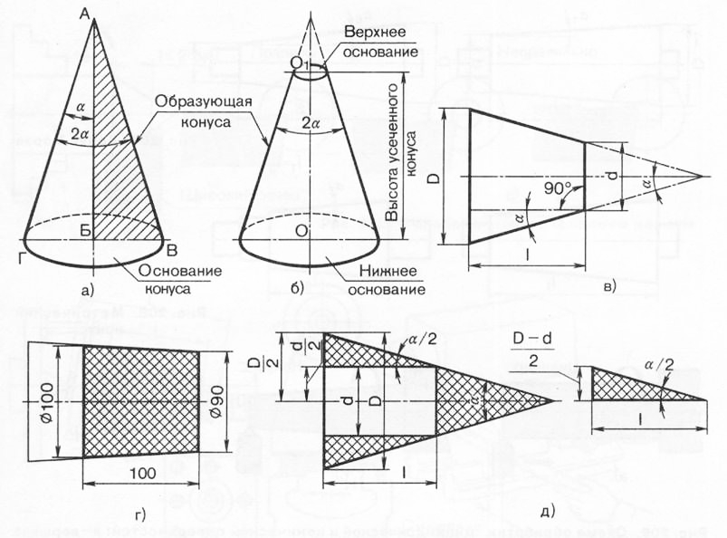
If rotate right triangle ABV around leg AB, then the resulting body is called a full cone, leg AB is the height of the cone. The line AB is called the generatrix of the cone, and the point A is its apex. When the leg BV rotates around the axis AB, a surface is formed, called the base of the cone. The angle between the generatrix AG and the axis AB is the angle a of the slope of the cone. The angle VAG between the generators AB and AG of the cone is called the angle of the cone; it is equal to 2a. If you cut off its upper part from a full cone by a plane parallel to the base, then the resulting body will be a truncated cone (Fig. 206.6), which has two bases - upper and lower. The distance 001 between the bases is the height of the truncated cone. The drawing usually indicates three main dimensions of the cone (Fig. 206, c): the larger diameter D, the smaller diameter d and the height of the cone.
Rice. 198. Application of drills for holemaking
Rice. 199. Devices for fastening drills
Using the formula tga = = (D- d) / (2l), you can determine the angle a of the inclination of the cone, which is set on the lathe by turning the upper support or shifting the tailstock. Sometimes the taper is set as follows: K \u003d (D - d) / l, i.e., the taper is the ratio of the difference in diameters to the length. On fig. 206, d shows a cone, in which K \u003d \u003d (100 -90) / 100 \u003d 1/10, i.e., over a length of 10 mm, the diameter of the cone decreases by 1 mm. Taper and cone diameter are related by the equation d = D - Kl, whence D = d + Kl.
If we take the ratio of the half-difference of the diameters of the cone to its length, then we get a value called the slope of the cone M \u003d (D - d) / (2l) (Fig. 206, e). The slope of the cone and the taper are usually expressed in ratios of 1:10, 1:50 or 0.1:0.05, etc. In practice, the formula is used
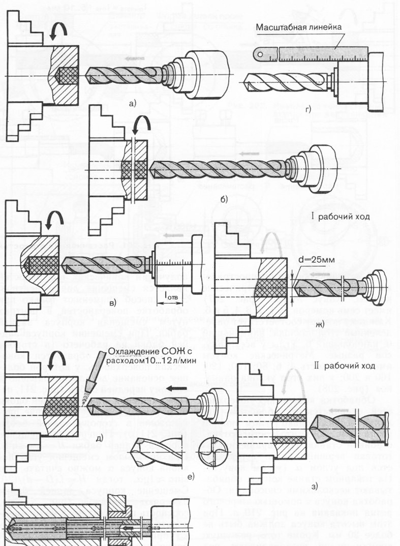
Rice. 200. Drilling blind and deep drain holes
Rice. 201. Hole boring
In mechanical engineering, Morse cones and metric cones are common. The Morse cone (Fig. 207) has seven numbers: 0, 1, 2, 3, 4, 5 and 6. Each number corresponds to a certain angle of inclination: the smallest is 0, the largest is 6. The angles of all cones are different. Metric cones have a taper of 4; 6; 80; one hundred; 120; 160 and 200; they have the same slope angle (Fig. 208).
The processing of conical surfaces differs from the processing of cylindrical ones only by the angle of the cutter feed (Fig. 209), which is achieved by setting the machine. When the workpiece is rotated, the tip of the cutter moves at an angle a (the angle of the cone). On a lathe, cones are processed in several ways. The processing of a cone with a wide cutter is shown in fig. 210 a. In this case, the height of the cone should be no more than 20 mm. In addition, the cutting edge of the cutter is set at an angle a to the axis of rotation of the part exactly along the height of the centers (Fig. 210.6).
Most in a simple way to obtain conical surfaces is the displacement of the line of centers. This method is used only when processing surfaces in the centers by shifting the tailstock body. When the body of the tailstock is shifted to the worker (towards the tool holder), a conical surface is formed, in which the larger base of the part is directed towards the headstock (Fig. 211, a). When the tailstock body is displaced from the worker, the larger base is located towards the tailstock (Fig. 211.6). Lateral displacement of the tailstock body H = L - sina. With a slight shift in the angle of inclination of the cone a, we can assume that sinaa;tga, then H = L(D - d)/(2l). The displacement of the tailstock body is measured with a ruler (Fig. 211, c), the alignment of the centers can also be checked with a ruler (Fig. 211, d). However, when shifting the body of the tailstock, it should be borne in mind that the shift is allowed no more than 1/50 of the length of the part (Fig. 211, e). With a larger offset, an incomplete fit of the center holes of the part and centers is formed, which reduces the accuracy of the machined surface.
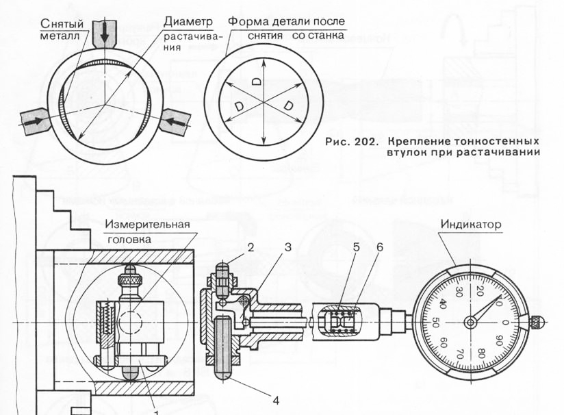
Rice. 203. Indicator inside gauge for measuring the depth of holes: 1 - centering bridge; 2-measuring tip; 3-double lever; 4-adjustable emphasis; 5-spring, eliminating the gap in the transmission elements; 6-measuring indicator rod
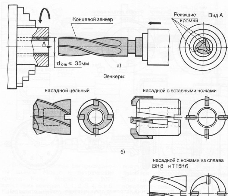
Rice. 204. Solid and mounted zenners
Rice. 205. Turn around
It is expedient to process cones with a large angle a and a small height by turning the upper support. This method is used when processing the outer (Fig. 212, a) and internal (Fig. 212.6) cone. In this case, manual feed is carried out by turning the handle of the upper support. To rotate the upper caliper to the required angle with mechanical feed, divisions are used, printed on the flange of the caliper turning part. If the angle a is not specified in the drawing, it is calculated using the formula tga = (D - d)/(2l). The cutter is set strictly in the center. Deviation from the straightness of the generatrix of the processed cone occurs when the cutter is installed above (Fig. 213.6) or below (Fig. 213, c) the center line.
To obtain conical surfaces with a ^ 10 ... 12 °, a copy ruler is used (Fig. 214). A ruler 2 is installed on the plate 1, which is turned at the required angle a around the pin 3 and fixed with a screw 6. The slider 4 is rigidly connected to the transverse part of the support 8 with the help of a rod 7 and a clamp 5. The copy ruler must be installed parallel to the generatrix of the cone, which must be obtained . The angle of rotation of the copy ruler is determined from the expression tga = (Z) - d)/(2l). If the divisions on the plate are indicated in millimeters, then the number of divisions is C - H (D - d) / (2l), where R is the distance from the axis of rotation of the ruler to its end.
A cone, in which the length of the generatrix is greater than the stroke length of the upper caliper carriage, is turned by applying longitudinal and transverse feeds (Fig. 215). In this case, the upper carriage must be rotated through an angle p relative to the center line: sinp = tga (Snp / Sn + 1), where OPR and Sn are the longitudinal and transverse feeds. To obtain a taper of the required shape, the cutter is set strictly in the center.
The conical hole is processed in the following sequence. A hole is drilled with a slightly smaller diameter than the diameter of the smaller base of the cone (Fig. 216), then the hole is drilled with a drill. After that, the stepped hole is bored with a cutter. Another way to obtain a conical hole is drilling a hole (Fig. 217, a), rough reaming (Fig. 217.6), semi-finishing (Fig. 217, c), finishing (Fig. 217, d).
Rice. 206. Geometric parameters of nonus
Conical surfaces are controlled by goniometers (Fig. 218, a), gauges (Fig. 218, b, c) and templates (Fig. 218, d). Tapered holes are checked for ledges and risks marked on the gauges (Fig. 219). If the end of the taper hole of the part coincides with the left end of the ledge, and outside diameter coincides with one of the marks or is located between them, then the dimensions of the cone correspond to the given ones.
Rice. 207. Morse taper
![]()
Rice. 208. Metric nonus
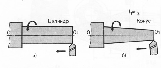
Rice. 209. Scheme for processing cylindrical and nonic surfaces: a-the top of the cutter moves parallel to the axis of the centers; b-the top of the cutter moves at an angle n to the axis of the centers
Development of a lesson on the topic "Processing of conical holes with a set of conical reamers" in the discipline "Industrial training".
specialty 1109000 "Turning and metalworking"; qualification 1109012 "Turner".
The theme of the program is "Processing of conical surfaces". 36 hours are allotted for the study of this topic. The duration of an industrial training lesson is a full academic day (six training hours). The topic "Machining tapered holes with a set of tapered reamers" is studied in one lesson.
This methodological development is to form in students the initial skills and abilities with high performance.
1. JUSTIFICATION OF THE DIDACTIC FEASIBILITY OF THE PROPOSED METHODOLOGICAL DEVELOPMENT
The process of industrial training is implemented in various forms.
The main forms of organization of industrial training:
Lesson, lesson in educational workshops;
Occupation in the workshop of the enterprise;
Internship.
A lesson in industrial training is an occupation in training workshops. Its specificity is the formation of the initial professional skills necessary for productive labor in production conditions.
Depending on the goals and content of the studied material, there are the following types industrial training lessons:
Lessons on the study of labor techniques and operations;
Lessons on the implementation of complex work;
Testing lesson.
The purpose of the lesson on the study of labor techniques and operations is to give students production and technical knowledge, initial skills and abilities to perform the studied techniques and operations.
The efficiency and effectiveness of a lesson is largely determined by its structure, which is understood as a didactically determined internal order and interaction.
"Naturally, students like innovative lessons more because of their unusual design, methods of organization and conduct, the absence of a rigid structure, the presence of conditions for self-realization, etc. Therefore, such lessons should be in the arsenal of every teacher.
At the same time, it should be taken into account that in such lessons, as a rule, there is no serious cognitive work of students, their effectiveness is low. Because of this, they should not predominate in the overall structure of teaching, the masters need to determine the place of non-traditional lessons in their work.
Therefore, the proposed development of a methodology for conducting an industrial training lesson on the topic "Machining conical holes with a set of conical reamers" is expedient. In this lesson, students will form the initial professional skills and abilities of processing tapered holes with a set of tapered reamers.
2. LESSON PLAN
Program theme:"Machining of conical surfaces"
Lesson topic:"Processing of conical holes with a set of conical reamers".
Lesson Objectives:
didactic:
To interest students in the process of production activities;
To form knowledge about safety precautions during deployment;
To acquaint students with a set of reamers for processing conical holes;
Build students skills:
* determine the diameter of the hole for deployment;
* prepare openings for deployment;
* install and fix the reamer in the tailstock quill;
* correctly perform deployment techniques;
Developing:
Develop abstract thinking;
Develop organization in the workplace;
Educational:
To cultivate a caring attitude towards tools and equipment, to develop determination and will in carrying out the planned work.
Lesson type: a lesson in the study of labor methods and operations.
Lesson methods: stories, conversations, personal demonstrations, techniques, exercises for performing techniques and deployment operations.
Educational and production work:
Material and technical equipment:
blanks;
Calipers;
Gauge-plugs;
Detail drawings;
instruction cards;
Sets of reamers for processing conical holes;
Drills are spiral.
During the classes.
Organizational part(5 minutes.):
Mark absent in the journal;
Compliance check appearance students safety rules.
Induction training(35 min.):
Message about the topic and purpose of the lesson;
Updating the basic knowledge of students on the topic of the lesson:
* talk about the purpose of the deployment;
* talk about the appointment and design features draft, semi-finishing and finishing sweeps;
Presentation of new material and personal demonstration of techniques:
* the value of deployment with a set of conical reamers for turning;
* determination of the diameter of the hole for deployment;
* preparation of openings for deployment;
* the procedure for fixing the reamer in the tailstock quill;
* technological process part manufacturing;
* advanced methods of work;
* analysis of the detail drawing, technical requirements,
* a warning against marriage at work;
* personal demonstration of techniques for deploying conical holes;
* the order of the exercises by students and self-control;
* safety precautions for the organization of the workplace during deployment;
Consolidation of the introductory briefing material:
* tell how to determine the diameter of the hole for deployment;
* tell and show the procedure for installing and securing the sweep and deployment techniques;
* talk about the procedure for preparing holes for deployment;
* talk about the technological process of the manufactured part;
* talk about safety precautions during deployment.
Student exercises and ongoing instruction (5:00):
Student exercises when deploying conical holes:
* install the workpiece in the chuck, the drill - in the quills, adjust the machine to the required number of revolutions;
* determine the diameter of the hole for deployment;
* drill a hole to the required diameter ( inner diameter parts, part length, hole length);
* check the hole diameter;
* install a rough scan in the quill;
* adjust the machine to the number of revolutions required during deployment;
* install and secure the tailstock at such a distance from the end of the part that the deployment can be carried out to the required length with a minimum extension of the quill from the tailstock body;
* move the reamer smoothly (without impact) to the end face of the workpiece;
* turn on the machine and perform a rough deployment;
* reinstall rough scan to semi-finish;
* perform a semi-finish deployment;
* reinstall the semi-finishing sweep on the finishing one;
* perform a clean deployment;
* remove the workpiece, turn off the machine;
Target visits to student workplaces:
* check the organization of jobs and the timeliness of the start of work;
* check the correctness of the methods of drilling holes for deployment and control methods;
* if necessary, when bypassing workplaces, provide assistance to students;
* check the correct implementation of deployment techniques;
* check the correctness of the methods of possession of control and measuring instruments;
* check the use by students in the process of work of the instruction card and drawing;
* check that students comply with safety regulations during deployment;
* provide individual assistance to students;
* check the quality of manufactured parts.
Final briefing (15 minutes.):
Report on the achievement of the objectives of the lesson;
Analyze the progress of the exercises;
Conduct a comparative analysis of the work of students and draw a conclusion;
Recognize excellent performance of students;
Identify and indicate the reasons for marriage;
Inform students of the assessment of the work performed;
Inform students about the topic of the next lesson;
Issue a task at home: draw up a technological process for manufacturing a part.
Stage of introductory briefing
Introductory briefing solves the following tasks:
a) familiarizing students with the content of the upcoming work and the means by which it can be performed (equipment, tools, fixtures, etc.);
b) familiarization with technical documentation and requirements for the final result (product) of labor;
c) explanation of the rules and sequence of work as a whole and its individual parts (techniques, operations, etc.);
d) warning students about possible difficulties, mistakes;
e) if necessary, showing methods of self-control over the performance of operations.
The activation of cognitive activity during the introductory briefing contributes to the actualization of previously acquired knowledge, practical skills and abilities, showing the practical significance of the studied material for professional activities.
When preparing for a lesson of industrial training, the master determines the organization and methodology of his activity, thinks over the activities of students at the stage of the lesson.
The organization for the introductory briefing includes the following.
It is necessary to check the serviceability and operability of equipment and tools, the availability of the necessary documentation and visual aids, blanks and materials for the implementation of training and production work. Arrange everything prepared in the order of use so that it is always at hand so that you do not have to spend time searching.
The basis of the introductory briefing is showing and explaining the techniques and methods for performing the operation being studied. At this stage of the introductory briefing, when the theoretical background forthcoming labor activity, the method of displaying labor actions is applied. The rule for applying this method is given in Table 1.
Table 1 Rules for applying the method of showing labor actions
| Master activity | Student activities | |
| Explanation of the purpose of generated skills Showing the entire workflow at a normal pace Isolation of operations, techniques and basic actions in the labor process Showing individual operations, techniques and methods for their implementation according to the instruction card Asking questions to analyze the instruction card Showing all learning activities in slow motion Challenge one or two students to play the actions shown | Understanding the importance of the labor process in professional activities Observation, holistic perception of the labor process Analysis of the composition and structure of labor activity Understanding how to perform each operation, how to work with an instruction card Answers on questions mental perception Observation, analysis | |
| Master activity | Student activities | |
| Analysis of student errors Repetition of the entire labor process at a normal pace | Analysis of working methods Mental reproduction of labor activity | |
Showing labor techniques, you need to skillfully combine practical demonstration and verbal explanations. You can not show techniques silently, but you should not be verbose at the same time. With the help of words, accompanying explanations are given, the attention of students is drawn to the most significant, to the "invisible" part of the technique, the results of the show are summed up.
The introductory briefing can only be completed when the master is convinced that the majority of students will be able to start successfully enough. If there is no such confidence, the briefing should be continued until the goal is achieved.
Stage of the current briefing
Current briefing is carried out in the course of implementation by students practical work. At this stage of the lesson, the master organizes a system of exercises for students; supervising the work of students, he observes the following basic rules:
1) observe the students during the exercises unnoticed by them;
2) delve into the work of each student, not losing sight of the work of the entire group;
3) provide assistance to students in a timely manner, accustoming them to independently overcome difficulties, but not allowing mistakes to be fixed;
4) do not finish the work for the students - this teaches them to be irresponsible
5) constantly accustom students to planning and systematic self-control of their work;
6) show strictness in the requirements for the implementation of labor safety rules and organization of workplaces;
7) not to interfere in the work of students without special need;
8) to ensure that students themselves understand their mistakes, realize them and find ways to correct and prevent them;
9) if the mistakes made are typical for most students, conduct collective current instruction of the entire group.
During the current briefing, the master focuses the attention of the entire training group on the most effective techniques and methods for performing the operation being studied.
The activation of the group is achieved by introducing a phased assessment of the performance of individual operations, the results of labor as a whole.
Final briefing stage
To improve the effectiveness of the final briefing, the following can be recommended:
1) Always put the summing up of the implementation of the learning tasks of the lesson in the foreground;
2) give the final briefing a learning character;
3) involve students in an active discussion of the results of the past lesson;
4) skillfully use the analysis of the best educational and production work of students;
5) analyze the results of the lesson comprehensively and objectively, give marks - to argue;
6) when issuing homework, be sure to instruct students on how to complete them.
4. SUMMARY OF THE NEW MATERIAL AND PERSONAL SHOW OF TECHNIQUES
Significance of reaming taper holes with a set of taper reamers for turning
On lathes, it is possible to machine tapered holes with a small taper angle with a set of tapered reamers.
By reaming, a precise and fine conical surface is obtained.
A set of conical reamers includes three reamers (roughing, semi-finishing, finishing), which sequentially pre-process drilled hole. Reamers have different cutting edge designs. The rough reamer has four cutting edges, the semi-finish reamer has six, and the finish reamer has eight.
Determining the hole diameter and preparing the hole for reaming
A hole for reaming in the workpiece is drilled with a diameter of 0.5 - 1.0 mm less than the diameter of the guide cone of the reamer.
A hole for reaming with a diameter of up to 25 mm is drilled with one drill, and if the hole diameter is more than 25 mm, it is recommended to drill successively with several drills of different diameters.
Preparing a hole for deployment. Before starting work, check the coincidence of the vertices of the front and rear centers machine. Then install the workpiece in the chuck and check that its runout (eccentricity) relative to the axis of rotation does not exceed the allowance removed during external turning. Also check the runout of the end face of the workpiece in which the hole will be machined (align the workpiece along the end face). Next, install the drill in the tailstock quill; make drilling; remove the drill, remove the chips.
The order of fixing the sweep
Fix the rough reamer in the conical hole of the tailstock quill: unclench the quill by turning the handle, install the reamer, clamp the quill.
Tapered Hole Reaming Techniques
Tailstock move along the bed to such a distance from the workpiece that the deployment can be performed to the required length with a minimum extension of the quill from the tailstock body;
Turn on the rotation of the spindle with the workpiece;
Bring the reamer smoothly (without impact) to the end of the workpiece;
Ream by removing chips from the part with a hook;
Reinstall the reamer (remove the rough reamer, fix the semi-finish one);
Perform a semi-finish deployment;
Take the reamer, remove chips;
Reinstall the reamer (remove the semi-finishing one, fix the finishing one);
Perform a clean deployment;
Take the reamer, remove chips;
Stop the rotation of the workpiece;
Remove workpiece;
Remove the reamer and clean it.
Deployment Safety and Workplace Organization
Traumatic factors that may appear during the deployment process are as follows: cutting tools; fixtures for fixing the workpiece; shavings.
Injury prevention. Cuts to the hands with the sharp edges of the cutting tool can occur during haste and incorrect methods of setting the scan. Students should use the instruction cards while performing the deployment techniques.
Special clothing protects the student's body from injury. The sleeves of overalls should fit the arms and fasten with buttons. Sleeve ties are not allowed, as their ends can be caught by the machine spindle or cams protruding from the end of the chuck. Wear headgear to avoid trapping hair.
When deploying, the reamer is periodically removed from the hole and its grooves and the workpiece hole are cleaned from accumulated chips using hooks and brushes. Overalls, special footwear protects against injury of parts of the body by shavings. The use of glasses, shields and protective screens prevents injury to the eyes by flying chips, burns of the eyes by hot parts of metals.
Safety regulations prohibit measuring parts while the machine is running, as this is associated with the risk of injury to workers with a cutting tool, workpiece or fixture.
conclusions
The organization of the workplace must ensure complete safety of work. There should not be anything superfluous, unnecessary, unused in work at the workplace. All items used in the work (a set of reamers, drills, measuring tools, etc.) must have permanent storage places.
Tapered Hole Machining
6. Processing of conical holes.
Methods for processing conical holes. The processing of conical holes can be carried out with the installed cutter, with the upper slide of the caliper rotated, using tapered ruler and deployment. The essence of the first three of these methods, the calculations associated with them and the methods for their implementation are the same as for the corresponding methods for processing external cones. Therefore, some features of the processing of conical holes in a solid material and the reaming of conical holes are considered below.
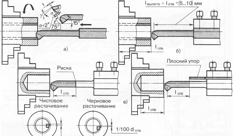
Peculiarities of processing conical holes in solid material. These holes are pre-drilled. The diameter of the drill used in this case should be 2-3 mm less than the smaller diameter of the cone. If the taper angle is large, then the hole thus obtained is reamed or bored with steps before boring. To do this, it is desirable to have a part (or exemplary cone) with an outer cone that is the same as the one being machined. For example, if the processed conical hole (Fig. 155, a) should have diameters D and d with a length l and there is an exemplary cone (Fig. 156) with the same dimensions, then the hole is pre-treated as follows.
Dividing the length of the exemplary cone, for example, into three parts, measure the diameters d2 and d1 and the distances /2 and 11 from the right end to the sections in which these diameters are measured. After the hole to be processed is drilled (Fig. 155, 6) with a drill whose diameter is 2-3 mm less than d, it is reamed (Fig. 155, c) first to a depth slightly less than /1 with a drill with a diameter of less than dlt and then (Fig. 155, d) to a depth slightly less than 4 with a drill whose diameter is less than d2. Then a hole is bored, which can be done much faster than if the taper was bored immediately after the first drilling (Fig. 155, b), when the machining allowance was much larger. When pre-treatment by drilling large conical holes on powerful machines, it is necessary to start with a larger drill and drill it to a depth of less than /2, then process the second ledge with a drill of a smaller diameter, etc.
In the absence of a model cone, the dimensions d1, d2, l1 and /2 can be determined by directly measuring them on the drawing of the part, taking into account the scale in which it is made, or by appropriate calculations.
The clearance angle of the cutter used when boring a conical hole should be 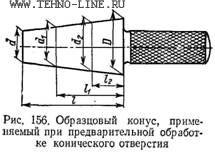 choose according to the smaller hole diameter. This angle, sufficient at the beginning of the cut, may be small when the cutter reaches the end of the hole being bored. As a result, friction will occur between the surface of the hole and the back face of the cutter, which is unacceptable for its operation.
Tapered hole reaming. Conical holes of normalized sizes (inner cones in adapter bushings, in shell reamers, countersinks, etc.) should be machined with reamers (Fig. 157), a set of which for a certain type and size of the machined conical hole (for example, Morse taper No. 4) consists of 3 pcs. Each of these reamers has a conical part corresponding to the size of the hole for which it is intended, and a cylindrical shank ending in a square. On the conical part, the grooves forming the teeth are milled. The first (peeling) reamer (Fig. 157, a) usually has a small number of teeth (the reamer for Morse cone No. 4 has six teeth). 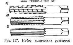 They are made stepped with the arrangement of steps along a helical line. The second scan (Fig. 157, b) has a significantly larger number of teeth than the first, but also stepped (to separate the chips being removed into parts). The third (finishing) reamer (Fig. 157, c) has straight, even teeth; they are made somewhat more than in the second scan.
The hole is drilled with a drill with a diameter of 0.5-1.0 mm less than the smaller diameter of the first reamer. Due to the stepped shape of the teeth of this reamer and their location along a helical line, the reamed hole is stepped. After the passage of the second sweep, the steps decrease in size, but their number increases. The last (finishing) sweep removes the steps, and the machined hole is obtained with smooth walls. A kit designed for machining tapered holes with small taper slopes sometimes consists of two reamers. Very shallow cones are often machined straight away with a fine reamer.
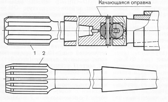
Setting the sweep during operation is shown in fig. 158. The working end 3 of the reamer is inserted into the workpiece hole 2, fixed in the chuck 1, and the right end is supported by the center 5 inserted into the quill 6 of the tailstock of the machine. A clamp 4 is put on the square end of the reamer, the end of which rests on top platform caliper. As the reamer moves to the left, the tailstock quill is also fed to the left by continuous rotation of its flywheel. If the end of the clamp approaches the left edge of the platform, move the entire caliper to the left. When processing steel parts, the reaming of conical holes must be carried out using a cutting fluid - emulsion, sulfofresol or vegetable oil mixed with kerosene and turpentine. 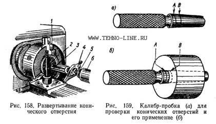
Checking taper holes. To check the conical holes, plug gauges are used (Fig. 159, c). When using such a caliber, chalk or pencil marks can be applied on the side surface of it. If, after the gauge is inserted into the hole to be checked and rotated several times, the marks are erased along the entire length, the taper angle of the hole is correct. If they wear off only at the smaller diameter of the caliber, this means that the taper angle is large. If the taper angle is too small, the chalk or pencil lines will be erased only at the large diameter of the caliber. The diameters of the conical hole are checked with a limiting plug gauge. With a correctly processed risk hole B, applied during manufacture on a plug gauge, must be closed by the part, and risk A must not be covered by the end of the part (Fig. 159, b). If the mark B on the gauge does not reach the end of the part, the hole should be processed additionally, and if the mark A goes deep into the part, the latter is a marriage. Sometimes, instead of notches, a ledge is made at the end of the cork gauge. The two ends of the ledge correspond to the through and through dimensions, between which the end of a correctly bored conical hole should be located.
Literature
1. Professional pedagogy: A textbook for students studying in pedagogical specialties and areas. - M.: Association " Professional education", 1997. - 512 p.
2. Skakun V.A. Introduction to the profession of master of industrial training: method. allowance. - 2nd ed. revised and additional - M.: Vyssh.shk., 1988. - 239 p.
3. Erganova N.E. Vocational training methodology: Tutorial. - Yekaterinburg.6 Publishing house Ros. state prof.-ped. un-ta., 2003. - 150 p.
4. Skakun V.A. Methodology of industrial training in diagrams and tables. Toolkit. - M.: Ed. Department of KNOW ISOM, 2004. - 175p.
5. Feshchenko V.N., Makhmutov R.K. Turning / Textbook for prof. those. textbook establishments. - 3rd ed. center "Academy", 1997. - 303 p.
The practical task contains 18 sheets of typewritten text, 1 table, 5 sources used.
Keywords: INDUSTRIAL TRAINING, WORK TECHNIQUES AND OPERATIONS, PROFESSIONAL SKILLS AND SKILLS, CONE HOLING, INSTRUCTION.
In a practical task, a methodology was developed for conducting an industrial training lesson on the topic "Machining conical holes with a set of conical reamers" to train students of the Yekaterinburg Vocational Lyceum in the profession "Turner".
The processing of conical surfaces on lathes is performed different ways: by turning the upper part of the caliper; displacement of the tailstock body; turning the conical ruler; wide cutter. The use of one or another method depends on the length of the conical surface and the angle of the cone.
Machining the outer cone by turning the upper slide of the caliper is advisable in cases where it is necessary to obtain a large cone slope angle with a relatively small length. The largest length of the generatrix of the cone should be somewhat less than the stroke of the carriage of the upper caliper. Processing the outer cone by shifting the body of the tailstock is convenient for obtaining long gentle cones with a small slope angle (3 ... 5). To do this, the body of the tailstock is shifted in the transverse direction from the line of machine centers along the guides of the base of the headstock. The workpiece to be processed is fixed between the centers of the machine in driving chuck with a collar. Processing of cones using a cone (copy) ruler, fixed on the back of the bed lathe on a plate, used to obtain a gentle cone of considerable length. The workpiece is fixed in centers or in a three-jaw self-centering chuck. The cutter, fixed in the tool holder of the machine support, receives simultaneous movement in the longitudinal and transverse directions, as a result of which it processes the conical surface of the workpiece.
The processing of the outer cone with a wide cutter is used if it is necessary to obtain a short cone (l<25 мм) с большим углом уклона. Широкий проходной резец, режущая кромка которого длинней образующей конуса, устанавливают в резце держатель так, чтобы главная режущая кромка резца составляла с осью заготовки угол а, равный углу уклона конуса. Обработку можно вести как с продольной, так и с поперечной подачей. На чертежах деталей часто не указывают размеры, необходимые для обработки конус и их необходимо подсчитывать. Для подсчета неизвестных элементов конусов и их размеров (в мм) можно пользоваться следующими формулами
a) taper K= (D-d)/l=2tg
b) cone slope angle tg = (D-d)/(2l) = K/2
c) slope i \u003d K / 2 \u003d (D - d) / (2l) \u003d tg
d) larger cone diameter D = Kl + d = 2ltg
e) smaller cone diameter d = D-- K1 = D--2ltg
e) the length of the cone l \u003d (D - d) K \u003d (D - d) / 2tg
The processing of internal conical surfaces on lathes is also performed in various ways: with a wide cutter, turning the upper part (sled) of the caliper, turning the conical (copy) ruler. Internal conical surfaces up to 15 mm long are processed with a wide cutter, the main cutting edge of which is set at the required angle to the cone axis, carrying out longitudinal or transverse feed. This method is used when the cone slope angle is large, and high requirements are not imposed on the accuracy of the cone slope angle and surface roughness. Internal cones longer than 15 mm at any angle of inclination are processed by turning the upper slide of the caliper using manual feed.
Regardless of the method of processing the cone, the cutter must be set exactly at the height of the centers of the machine.
1. Wide cutter
When machining shafts, there are often transitions between machined surfaces that have a conical shape, and chamfers are usually removed at the ends. If the length of the cone does not exceed 25 mm, then it can be processed with a wide cutter (Fig. 2).
The angle of inclination of the cutting edge of the cutter in the plan must correspond to the angle of the taper on the workpiece. The cutter is fed in the transverse or longitudinal direction.
It should be borne in mind that when processing a cone with a cutter with a cutting edge longer than 10-15 mm, vibrations may occur, the level of which is the higher, the longer the length of the workpiece, the smaller its diameter, and the smaller the angle of inclination of the cone. As a result of vibrations, traces appear on the treated surface, and its quality deteriorates. This is due to the limited rigidity of the system: machine tool - fixture - tool - part (AIDS). When machining rigid parts with a wide cutter, vibrations may be absent, but at the same time, the cutter may be displaced under the action of the radial component of the cutting force, which leads to a violation of the cutter setting to the required slope angle.
Advantages of the method:
1. Easy to set up.
2. Independence of slope angle a on the dimensions of the workpiece.
3. Ability to process both external and internal conical surfaces.
Disadvantages of the method:
1. Manual feed.
2. Limitation of the length of the generatrix of the cone by the length of the cutting edge of the cutter (10–12 mm). With an increase in the length of the cutting edge of the cutter, vibrations occur, leading to the formation of surface waviness.
2. By turning the upper slide of the caliper
 Tapered surfaces with large slopes can be processed by turning the upper slide of the caliper with the tool post at an angle a, equal to the slope angle of the processed cone
(Fig. 3).
The rotary caliper plate, together with the upper slide, can be rotated relative to the cross slide, for this, the nut of the plate fastening screws is released. The control of the angle of rotation with an accuracy of one degree is carried out according to the divisions of the rotary plate. The position of the caliper is fixed with clamping nuts. Giving is made manually by the handle of movement of the top sled.
In this way, conical surfaces are processed, the length of which is commensurate with the stroke length of the upper slide (up to 200 mm).
Advantages of the method:
1. Easy to set up.
2. Independence of slope angle a on the dimensions of the workpiece.
3. Processing of a cone with any angle of inclination.
4. Ability to process both external and internal conical surfaces.
Disadvantages of the method:
1. Limitation of the length of the generatrix of the cone.
2. Manual feed.
Note: Some lathes (16K20, 16A30) have a mechanism for transmitting rotation to the screw of the upper caliper slide. On such a machine, regardless of the angle of rotation, it is possible to obtain automatic feeding of the upper slide.
3. Offset of the body of the tailstock of the machine
Conical surfaces of great length with
a= 8-10° can be machined when the tailstock is offset, the value of which is determined as follows (Fig. 4):
H= L×sin a ,
where H - the amount of displacement of the tailstock;
L- the distance between the supporting surfaces of the center holes.
It is known from trigonometry that for small angles the sine is practically equal to the tangent of the angle. For example, for an angle of 7º, the sine is 0.120, and the tangent is 0.123. The tailstock displacement method processes workpieces with a small slope angle, so we can assume that sin a=tg a. Then
H= L×tg a = L×( D –d)/2l .
The workpiece is installed in the centers. The body of the tailstock with the help of a screw is displaced in the transverse direction so that the workpiece becomes “skewed”. When the caliper carriage feed is turned on, the cutter, moving parallel to the spindle axis, will grind the conical surface.
The amount of displacement of the tailstock is determined by the scale printed on the end face of the base plate from the flywheel side, and the risk on the end face of the tailstock housing. The division value on the scale is usually 1 mm. In the absence of a scale on the base plate, the tailstock offset is read off the ruler attached to the base plate. The position of the tailstock for taper machining can be determined from the finished part. The finished part (or sample) is installed in the centers of the machine and the tailstock is shifted until the generatrix of the conical surface is parallel to the direction of the longitudinal movement of the caliper.
To ensure the same conicity of a batch of parts processed in this way, it is necessary that the dimensions of the workpieces and their center holes have slight deviations. Since misalignment of the machine centers causes wear of the center holes of the workpieces, it is recommended to machine the conical surfaces first, then correct the center holes, and then finish finishing. To reduce the breakdown of the center holes, it is advisable to use ball centers. The rotation of the workpiece is transmitted by a driving chuck and clamps.
Advantages of the method:
1. Possibility of automatic feeding.
2. Obtaining workpieces commensurate in length with the dimensions of the machine.
Disadvantages of the method:
1. The impossibility of processing internal conical surfaces.
2. The impossibility of processing cones with a large angle ( a³10º). It is allowed to shift the tailstock by ±15mm.
3. The impossibility of using center holes as base surfaces.
4. Angle dependency a on the dimensions of the workpiece.
4. Using a copy (cone) ruler
The processing of conical surfaces using copiers is common (Fig. 5).
A plate 1 is attached to the machine bed, with a copy ruler 2, along which the slider 4 moves, connected to the transverse carriage of the upper support 5 of the machine by a rod 6. For free movement of the support in the transverse direction, it is necessary to disconnect the transverse feed screw. When moving the longitudinal support 8 along the guides of the frame 7, the cutter receives two movements: longitudinal from the support and transverse from the copy ruler 2. The amount of transverse movement depends on the angle of rotation of the copy ruler 2. The angle of rotation of the ruler is determined by the divisions on the plate 1, the ruler is fixed with bolts 3. The cutter is fed to the depth of cut by the handle for moving the upper slide of the caliper.
The method provides high-performance and accurate processing of external and internal cones with a slope angle of up to 20º.
Advantages of the method:
1. Mechanical feed.
2. Independence of the taper angle a on the dimensions of the workpiece.
3. The possibility of processing both external and internal surfaces.
Disadvantages of the method:
1. Limiting the length of the generatrix of the cone by the length of the cone ruler (on machines of medium power - up to 500 mm).
2. Restriction of the slope angle by the scale of the copy ruler.
For the processing of cones with large slope angles, tailstock offset and adjustment along the cone ruler are combined. To do this, the ruler is rotated to the maximum allowable angle of rotation. a´, and the tailstock offset is calculated as when turning a cone, in which the slope angle is equal to the difference between the given angle a and the angle of rotation of the ruler a´, i.e.
H= L×tg ( a – a´) .


Chicken in kefir - recipes for marinated, stewed and baked poultry for every taste!
Simple Chicken Recipe in English (Fried) Recipes in English with translation
Chicken hearts with potatoes: cooking recipes How to cook delicious chicken hearts with potatoes
Recipes for dough and fillings for jellied pies with mushrooms
Stuffed eggplant with chicken and mushrooms baked in the oven with cheese crust Cooking eggplant stuffed with chicken