Designed for machining holes with precise axes, the dimensions between which are specified in a rectangular coordinate system. The machine can perform drilling, light (finishing) milling, marking and checking linear dimensions, in particular, and intercenter distances. The machine is equipped with rotary tables, which makes it possible to process holes specified in the polar coordinate system, inclined and mutually perpendicular holes and turning end planes.
Jig boring machine 2A450, 2D450, 2E450, 2E450AF30, 2450 is used for work in tool shops (processing of conductors and fixtures) and in production shops for precision machining of parts without special equipment. The machine is equipped with optical screen reading devices that allow you to count the integer and fractional parts of the coordinate size. Under normal operating conditions, the machine ensures the accuracy of setting the center-to-center distances in a rectangular coordinate system - 0.004 mm.
Machine 2A450 - single-column type, has a rectangular table with longitudinal and transverse movement. The adjusting movement of the spindle head is provided.
The working and accelerated movement of the table in the longitudinal and transverse directions are carried out electric drives with a wide range of regulation, allowing to increase the rigidity and productivity of the machine during milling.
Precise setting of the table to a given coordinate is done manually, with a handwheel. The machine is equipped with a digital indication device, enabling the operator to set coordinates with a resolution of 0.001 mm.
The spindle is rotated by an adjustable electric drive alternating current through a three-speed gearbox. Spindle feeds are carried out steplessly using a friction variator. There is a mechanism for automatic shutdown of the spindle feed at a given depth.
The machine is provided with mechanical clamps of the table, sled and manual clamping of the headstock.
Machine accuracy class A according to GOST 8-71
Table working surface (length x width), mm 1100x630
The greatest movement of the table, mm:
longitudinal
transverse
lO0O
630
Distance from spindle nose to table surface, mm:
greatest
least
750
250
Distance from the spindle axis to the rack (outreach), mm 710
The largest drilling diameter, mm 30
The largest boring diameter, mm 250
The greatest weight of the processed product, kg 600
Coordinate setting resolution, mm 0.001
Coordinate setting accuracy, mm 0.005
Diameter of universal turning table, mm 440
Diameter of horizontal rotary table, mm 600
Spindle bore taper (special) 5°
The largest taper of the Morse tool No. A
The greatest movement of the spindle, mm 250
The greatest movement of the spindle head, mm 250
Spindle RPM limits 50-2000
Spindle feed limits, mm/rev. 0.03-0.16
Table travel speed, mm/min working (during milling):
working (when milling)
accelerated
Machine dimensions, including table and slide travel (length x width x height), mm
Machine weight (without electrical cabinet and accessories), kg
20..315
1200
2670 x 3305 x 2660
7300
Modifications
- 2450, 2L450A - 1100 x 630 coordinate boring machine with an optical coordinate system along the X and Y axes
- 2A450AF10, 2D450AF10 - jig boring machine with a digital indication device along the X and Y axes (DRO). Electronic flywheel mode.
- 2D450AF11-01, 2L450AF11-01 - jig boring machine with a digital indication device along the X, Y and Z axes and a preliminary set of coordinates along the X and Y axes. There is a servo positioning mode and an electronic flywheel mode with a table displacement resolution of 0.001 and 0.01 mm .
- 2L450A, 2L450AF11-015, 2L450AF4-02 - jig boring machine with a universal rotary dividing table with a faceplate diameter of 400 mm.
- 2E450AF30 - jig boring machine with device numerical control(CNC) with the ability to set the processing program in the dialog mode along the X and Y axes and digital indication of the coordinates along the Z axis.
- 2450A, 2D450, 2D450A, 2E450A - 1120 x 630 coordinate boring machine with an optical coordinate system along the X and Y axes
- 2450AF1, 2D450AF1, 2E450AF1 - jig boring machine with digital indication device (DRO)
- 2450AF2, 2D450AMF2, 2E450AMF4, 2L450AF4-02 - jig boring machine with numerical control (CNC)
- 2E450AF4, 2E450AMF4 - a jig boring machine with a numerical control device (CNC) with contouring along the X, Y and Z axes. The graphic monitor allows you to debug programs without moving along the axes. Part programs can be prepared online with standard text files or automated systems.
Machine manufacturer Moscow plant of jig boring machines MZKRS and Kuibyshev plant of jig boring machines (Kuibyshev Machine Tool Association). The history of the Kuibyshev plant of coordinate boring machines dates back to 1963, when the first stage of this enterprise was commissioned. The young team of the plant in a short time mastered the production of high-precision machine tools and already in 1966 produced several hundred of them.
The plant ceased to exist in 1991, and several machine-tool enterprises were opened on its production facilities, which continue to produce coordinate boring machines engaged in their repair and modernization. Plant of jig boring machines "Stan-Samara" CJSC, Samara Research and Production Enterprise of jig boring machines, CJSC, "Stankoservis" LLC, etc.
It is intended for processing holes with the arrangement of axes, the dimensions between which are given in a rectangular coordinate system.
Along with boring on the machine, if necessary, drilling, light (fine) milling, marking and checking linear dimensions, in particular center distances, can be performed.
Using the rotary tables and other accessories supplied with the machine, it is also possible to machine holes specified in the polar coordinate system, inclined and mutually perpendicular holes and turning end surfaces.
The machine is suitable for work both in tool shops and in production shops for precise machining of parts without special equipment.
Technical characteristics of the machine 2A450 this is the main indicator of the suitability of the machine to perform certain work. For jig boring machines, the main characteristics are:
- table top size
- largest diameter drilling processing
- largest turning diameter
- distance from the end of the spindle to the working surface of the table
- spindle revolutions per minute
Below is a table with the technical characteristics of the 2A450 screw-cutting lathe. In more detail, the technical characteristics of the screw-cutting lathe can be found in the passport of the machine 2A450
| Name of parameters | Unit. | Quantities |
| Working surface of the table (LxW) | mm | |
| The greatest longitudinal movement of the table | ||
| The greatest transverse movement of the table | ||
| Distance from the end of the spindle to the working surface of the table | mm | 250...750 |
| Maximum spindle travel | ||
| Departure of a spindle from a rack | ||
| Spindle speed limits (stepless) | rpm | 50...2000 |
| Feed limits per spindle revolution | ||
| Maximum drilling diameter in steel in solid material | ||
| Large bore diameter | ||
| Permissible workpiece weight when installed on the machine table | ||
| The amount of rapid movement of the table and sled | ||
| The amount of movement of the product during milling | ||
| Spindle motor power | ||
| Spindle motor speed | ||
| Machine dimensions | 2670x3305x1266 |
|
| Machine weight |
Attention! The specifications in the above table are for reference only. Machine tools manufactured by different manufacturers and in different years may have characteristics different from those given in the table.
Passport of the machine 2A450
This instruction manual " Passport of the machine 2A450"contains information necessary for both the maintenance personnel of this machine and the employee directly work-related on this machine. This manual is an electronic version in PDF format, the original paper version. This documentation contains the Passport and the Manual (instruction) for the operation of the 2A450 machine.
- Purpose of the machine
- Technical specifications machine tool
- Requirements for the operating conditions of the machine
- Transportation of the machine
- Installation of the machine and connection to the electrical network
- Passport of jig boring machine
- Description of the kinematic diagram of the machine
- Launch preparation
- Machine control
- Optical coordinate reference system
- Machine safety
Download passport of the jig boring machine 2A450 good quality you can follow the link below.
Passport of the machine 2A450, coordinate boring. Free download.
Kinematic diagram of the machine 2A450"
You can download the kinematic diagram of the 2A450 jig boring machine in good quality from the link below.
Kinematic diagram of the machine 2A450. Free download.
Electrical diagram of the machine 2A450
Below is a sketch of one documentation page" Scheme of the machine 2A450"

You can download for free the electrical circuit of the 2A450 jig boring machine in good quality from the link below:
Electrical diagram of the machine 2A450, jig boring. Free download.
You can view more additional information on "Machine 2A450" at the link below:
Information about the manufacturer of the jig boring machine 2A450
Manufacturer of jig boring machine 2А450 Moscow plant of coordinate boring machines "MZKRS", founded in 1942 and Kuibyshev Plant of Coordinate Boring Machines(Kuibyshev machine-tool association).
The history of the Kuibyshev plant of coordinate boring machines dates back to 1963, when the first stage of this enterprise was commissioned. The young team of the plant in a short time mastered the production of high-precision machine tools and already in 1966 produced several hundred of them.
The plant ceased to exist in 1991, and several machine-tool enterprises were opened on its production facilities, which continue to produce jig boring machines, repair and modernize them: Plant of coordinate boring machines "Stan-Samara" CJSC; Samara Research and Production Enterprise for Coordinate Boring Machines, LLC "NPP KRS"; "Stankoservis" LLC, etc.
Coordinate boring machines. General information
Synonyms: jig boring machine, jig boring machine.
Coordinate boring machines are designed for processing holes in conductors, fixtures and parts that require high accuracy in the relative position of holes (within 0.005 - 0.001 mm), without the use of tools for guiding the tool.
These machines can be used for boring, drilling, countersinking and reaming of holes, fine milling of ends, measurement and control of parts, as well as marking work.
Machines can be used for processing holes in conductors, fixtures and parts that require high accuracy in the relative position of the holes. Along with boring, marking and checking of linear dimensions, in particular center-to-center distances, can be performed on machines. Using the rotary tables and other accessories supplied with the machine, it is also possible to machine holes specified in the polar coordinate system, inclined and mutually perpendicular holes and machine end surfaces.
Coordinate boring machines are designed for processing holes with the exact location of their axes without the use of markings. The accuracy of the location of the holes is achieved on these machines in the range of 0.005-0.001 mm. These machines can be used for drilling, reaming, reaming, boring and surface milling (milling is rarely performed). Coordinate boring machines are also used for measuring and controlling parts, for precise marking work.
Coordinate boring machines are more often used in tool and experimental shops.
Coordinate boring machines are single and double-column.
Single-column machines have a cross table designed to move the workpiece in two mutually perpendicular directions.
Two-column machines have a table located on the guides of the bed. The table moves the workpiece placed on it only in the direction of the x-coordinate. Racks are located on both sides of the bed, a cross member is placed on them, on the guides of which there is a spindle head. When the headstock moves along the guides of the crossbar, the spindle axis moves relative to the product installed on the table in the direction of the second coordinate y. To raise or lower the headstock, the crossbar is moved up or down along the rack guides. In all types of jig boring machines, holes are machined with a vertical spindle feed with a fixed spindle head and table.
In order to obtain a more accurate distance between the centers of the holes, jig boring machines should be installed in separate rooms, in which it is always necessary to maintain a constant temperature of +20 ° C with a deviation of no more than ± 1 °.
The measurement of the distance between the axes of the holes can be carried out using:
- rigid and adjustable limit measures used in combination with indicator devices
- precision lead screws with limbs and verniers
- accurate scales in combination with optical instruments
- inductive feedthrough screw sensors
According to the first method measured with a set of gauge blocks and a gauge. They are located between a movable stop mounted on a table and an indicator pin mounted on a fixed stand.
According to the second method measured with precision-made lead screws, which are designed to move the table and other parts. The amount of movement is counted by a limb with a vernier. To eliminate lead screw errors, correction rulers are often used, which, through a lever system, produce additional movement of the table.
The measurement is counted according to the third method on a very precise scale observed through a microscope. The scale is a mirror steel shaft with a thin helical risk applied on its surface with a step t = 2 mm or in the form of a flat mirror scale. The advantage of this measurement method is that there is no wear on the mirror shaft or mirror scale, which are not used to move the table.
Fourth measurement method using inductive screw probes provides the possibility of remote less tiring observation of the arrow and the scale of the electric indicator.
2A450 Single-column jig boring machine. Purpose and scope
The 2A450 jig boring machine is designed for machining holes with precise axes, the dimensions between which are specified in a rectangular coordinate system.
On the machine, you can perform drilling, light (finish) milling, marking and checking linear dimensions, in particular, center-to-center distances. The machine is equipped with rotary tables, which makes it possible to process holes specified in the polar coordinate system, inclined and mutually perpendicular holes and turning end planes.
The machine is used for work in tool shops (processing of conductors and fixtures) and in production shops for precise processing of parts without special equipment.
The 2A450 jig boring machine has the feature that it can produce a preliminary set of coordinates during the processing of the previous hole; this greatly reduces the downtime.
The machine is equipped with an optical measuring system of coordinates: the digitized risks of the glass dashed ruler are projected onto a fixed raster, with which you can directly, in one place, count all the decimal places of the coordinate being set.
The machine can drill holes up to 40 mm in diameter, mark precise templates, check linear dimensions and center distances. You can also perform small milling work on it.
The machine is used in tool, machine-building and instrument-making workshops for processing blanks of parts, both single-piece and serial production.
The machine is equipped with optical screen reading devices that allow you to count the integer and fractional parts of the coordinate size. Under normal operating conditions, the machine ensures the accuracy of setting the center-to-center distances in a rectangular coordinate system - 0.004 mm.
Precise setting of the table to a given coordinate is done manually, with a handwheel. The machine is equipped with a digital indication device, enabling the operator to set coordinates with a resolution of 0.001 mm.
Spindle rotation is carried out from an adjustable AC electric drive through a three-stage gearbox. Spindle feeds are carried out steplessly using a friction variator. There is a mechanism for automatic shutdown of the spindle feed at a given depth.
The machine is provided with mechanical clamps of the table, sled and manual clamping of the headstock.
Machine accuracy class A according to GOST 8-71.
Modifications of the coordinate boring machine 2A450
2450, 2L450A- 1100 x 630 coordinate boring machine with an optical coordinate system along the X and Y axes
2A450AF10, 2D450AF10- jig boring machine with a digital display device along the X and Y axes (DRO). Electronic flywheel mode.
2D450AF11-01, 2L450AF11-01- jig boring machine with a digital indication device along the X, Y and Z axes and a preliminary set of coordinates along the X and Y axes. There is a tracking positioning mode and an electronic flywheel mode with a table displacement resolution of 0.001 and 0.01 mm.
2L450A, 2L450AF11-015, 2L450AF4-02- jig boring machine with a universal rotary dividing table with a faceplate diameter of 400 mm.
2E450AF30- jig boring machine with a numerical control device (CNC) with the ability to set a processing program in a dialog mode along the X and Y axes and digital indication of the coordinates along the Z axis.
2450A, 2D450, 2D450A, 2E450A- 1120 x 630 coordinate boring machine with an optical coordinate system along the X and Y axes
2450AF1, 2D450AF1, 2E450AF1- jig boring machine with digital display device (DRO)
2450AF2, 2D450AMF2, 2E450AMF4, 2L450AF4-02- jig boring machine with numerical control device (CNC)
2E450AF4, 2E450AMF4- jig boring machine with a numerical control device (CNC) with contouring along the X, Y and Z axes. The graphic monitor allows you to debug programs without moving along the axes. Part programs can be prepared online with standard text files or automated systems.
2A450 Dimensions of the working space of the jig boring machine


2A450 General arrangement and composition of the jig boring machine

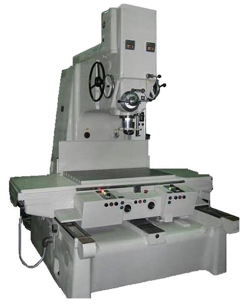
General form and layout of the machine are shown in fig. 34, a.
The machine consists of the following main units: bed 1, rack 9, spindle head 5, table 3, sled 2. An optical system is used to accurately measure the movements of the table and sled in the machine.
The design and characteristics of the main components of the jig boring machine 2A450
bed 1 (Fig. 34, a) is the base of the machine. The sled is moved along its two flat and one T-shaped (middle) guides. The back of the frame serves as a support surface for the rack 9.
On the rack 9 are placed: a block of 6 guides, a gearbox 7 and a casing 8 of the V-belt transmission. Block b has guides for vertical movement and fastening of the headstock 5. Gearbox 7 is fixed on its upper part.
AT headstock 5 there is a sleeve 4 with a spindle. Raising and lowering the headstock is performed by rotating the handwheel 13.
Table 3 is designed to install workpieces on it and move them in the direction of the X coordinate, which occurs when the table moves along the longitudinal guides of the slide.
Sled 2 serve to move the table and the workpiece mounted on it in the direction of the y coordinate when the sled moves along the transverse guides of the frame 1.
Moving the workpiece to the position required for processing the next hole can be done either by manually controlling the movements of the table and slide, or with a preliminary set of coordinates.
Controlling table movements manually is performed by turning the knob 1 (Fig. 34, d) from the zero position to the division indicating the speed of the table movement (in mm / min). At the moment of turning the regulator, the table is spun, while the red light 3 goes out and the green light 4 lights up. Then the table moves at the set speed in the direction corresponding to the inscription and the arrow. The new position of the table is counted roughly on the ruler scale 6 and pointer 7.
When the table approaches the desired position, the speed of its movement should be reduced by turning the knob 1 and then turned off by setting the zero scale of the knob 1 against the fixed line a.
The lateral movement of the slide is controlled by the regulator 11 and in the same way as the control of the table movements.
Preliminary set of table and sled travel reduces the time to set them in the desired position.
The direction of movement of the table is set by switch 5 (Fig. 34, d). To move the table to the left, the switch turns to the left (in the direction of the arrow b). With this position, the amount of movement of the table to the left is set on the scales: d - limb 9 and e - vernier 8.
To move the table to the right, switch 5 is turned to the right (in the direction of the arrow c). In this case, the amount of movement of the table to the right is set on the scales: g - limb 9 and g - vernier 8.
The desired amount of table movement is dialed by rotating the dial 9. For each revolution of the dial, the table travel increases (or decreases) by 100 mm. Divisions and numbers on the scales e and j vernier 8 indicate the set travel of the table in hundredths of a millimeter. Scales r, d and divisions on the limb 9 allow you to set the table stroke with an accuracy of a millimeter, and the lines of the vernier 8 - with an accuracy of tenths of a millimeter. The countdown of the table stroke to be set must always be made from the zero divisions of the limbus and vernier.
Preliminary set of the desired direction and amount of travel of the sled is made by another switch and dial, arranged in exactly the same way as switch 5 and dial 9, but located on the right side of the sled.
After pre-setting the direction of movement and the travel values of the table and sled, you can turn the switch 13 (Fig. 34, d) to the “set of coordinates” position at any necessary moment and by pressing the button 12 “working out” turn on the fast movement of the table and sled. At the same time, the table and slide will begin to move the workpiece with a rough accuracy (up to 0.1 mm) to the position for processing the next hole. When the zero of the dial scale 9 approaches the zero of the vernier scale 8, the table and sled will stop. The exact installation of the table and sled is carried out using optical screens 10 and 17 (Fig. 34, a).
Optical devices. Accurate measurement of the values of the coordinate displacements of the table and sled is carried out by optical devices and precision glass rulers. The table ruler has 1000 and the slide ruler 630 divisions. Each division is equal to one millimeter.
The optical devices of the table and sled are the same, therefore, we will only consider a device for accurately measuring the movements of the table in the longitudinal direction (Fig. 34, c).
The beam of rays from the lamp 1 illuminates the scale of the ruler 3 through the lens system. Using the lens 4, prisms, lenses and two optical wedges 5, the image of strokes and numbers of the precision ruler 3, magnified by 5 times, is transferred to the raster plane 7.
On the raster, a drawing is made that is necessary for an accurate reading of the position of the table. This drawing and the image of the stroke and numbers projected onto it from the precision ruler is enlarged by the lenses of the eyepiece 8 by another 25 times and in this form is transferred to the screen 11. At the same time, the distance between the strokes, equal to 1 mm on the scale bar, is projected onto the screen magnified by 125 times , i.e. equal to 125 mm.
The glass ruler 2 protects the strokes and numbers printed on the precision scale ruler 3 from dust. The protective glass 9 protects the internal cavity of the screen 11 from contamination. Mirror 10 directs raster image 7 to screen 11.
The raster pattern 7 and the image of the stroke and numbers of the scale bar 3 projected onto the screen make it possible to determine with great accuracy the movement of the table from the extreme position. The amount of table movement should be read on the screen (Fig.34, 6) sequentially in whole, tenths and thousandths of a millimeter. An integer is written above the vertical stroke e. Tenths of a millimeter are read in a row, but above the slanted line b of the raster, which is intersected by the stroke e.
In two vertical columns q are numbers indicating thousandths of a millimeter. On this scale, you need to find what number of the scale corresponds to the point of intersection of the stroke e with the inclined line b of the raster. For the convenience of reading, they are guided by the fact that the horizontal lines in serve to count each 0.010 mm, and the circles r - to count each 0.002 mm. If the stroke e crosses the inclined line b between two adjacent circles, then a thousandth of a millimeter should be added to the reading.
For example, the image shown in Fig. 34, b, and from it you can read the amount of movement of the table from the extreme right position. The number 213, written above the stroke e, indicates an integer in mm (213 mm). The number 2, written above that line b of the raster, which is intersected by the stroke e, indicates tenths of a millimeter (0.2 mm).
Thousandths of a millimeter are found by the numbers of the vertical scale d, projecting onto it the point of intersection of the inclined line b of the raster with the stroke e (0.042 mm).
Adding these values, we get x \u003d 213 + 0.2 + 0.042 \u003d 213.242 mm - the distance that the table has moved in the direction of the x coordinate from the extreme right position.
It is desirable that, with the initial position of the table, the reading on the screens would begin with an integer number of millimeters. This is achieved by shifting the stroke image on the screen within ±0.5 mm of reading. To do this, optical wedges 5 (Fig. 34, c) are rotated by flywheels 2 and 10 (Fig. 34, d).
To improve the accuracy of optical readings, the machine is equipped with rulers, which, with the help of a pusher and a lever, tilt the plane-parallel plate 6 (Fig. 34, c). This achieves a shift of the image on the screen of the sighted stroke by the amount of correction.
2A450 Kinematic diagram of a jig boring machine
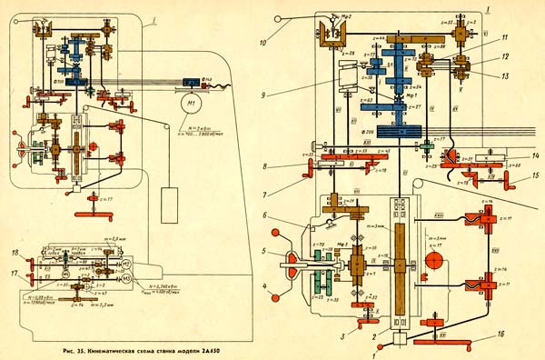
Kinematic scheme of the machine
The kinematic diagram of the machine is shown in fig. 35
Movements in the machine: main movement, vertical movement of the spindle, longitudinal movement of the table, transverse movement of the slide, vertical movement of the headstock.
Kinematic chain of the drive of the main movement. Spindle III is driven by a DC motor M1, the speed of which can be varied between 700 and 2800 rpm.
In addition, to increase the range of speeds, you can turn on the flywheel 7 to turn on any of the three steps of the speed of the spindle III. Flywheel 7 turns shaft XI and gears z=18, z=18, z=45, 2=33, z=33.
The first gear wheel z=33 turns the shaft XII and the drum cam 9, which switches the B1 unit and the Mf1 clutch through the levers, including one of the following three steps of the spindle speed III: 50-200 or 145-575, or 505-2000 rpm . These frequency ranges alternately appear in the pointer hole 14 (Fig. 34, a) when the disk 8 is turned (Fig. 35).
The change in the gear ratio of the friction variator, and, consequently, the value of the vertical feed of the spindle sleeve is made by rotating the flywheel 15. At the same time, through the gears z=18, z=18, z=31, z=25, the screw is moved up or down - thrust XV , which pushes or shifts the cones 11 of the variator. The amount of feed to be set is indicated on disk 14.
The feed direction is changed by turning the handle 10, which switches the Mf2 clutch. At the middle position of the handle, the Mf2 clutch and the supply of the spindle sleeve are disabled.
The feed is switched on by turning the double handles 4 “away from you”. At the same time, the cone 5 separates the pushers, including the MfZ clutch, which transmits rotation from the worm wheel z=56 to the shaft IX and the rack and pinion gear z=15. To turn off the feed by turning the handle 4 “towards you”, the MfZ clutch is disconnected.
Automatic shutdown of the feed when machining holes to a given depth is performed by cam 6.
To set the desired amount of stroke, the spindle is first lowered into a position in which the tool is brought to the surface to be machined. Then, by turning the handle 12 (Fig. 34, a), the limb 11 is released from the clamp and rotated to a position in which the division of the limb, indicating the desired amount of spindle travel, coincides with the zero risk of the vernier a. In this position, the limb is fixed. When setting the desired spindle travel, the dial should only be turned counterclockwise in order to eliminate play in the gear engagement.
After that, by moving the double handles 4 “away from you” (Fig. 35), the spindle feed is turned on. When the feed is on, the limb receives rotation from the shaft IX through the wheels with the numbers of teeth z=58, 2=35, 2=23 and 2=70. The spindle will descend to a position where the zero of the dial scale coincides with the zero of the vernier a. With this position of the limb, the cam 6 will disengage the gear wheel r = 21, as a result of which the rotation of the shaft VIII and the vertical feed of the spindle will stop.
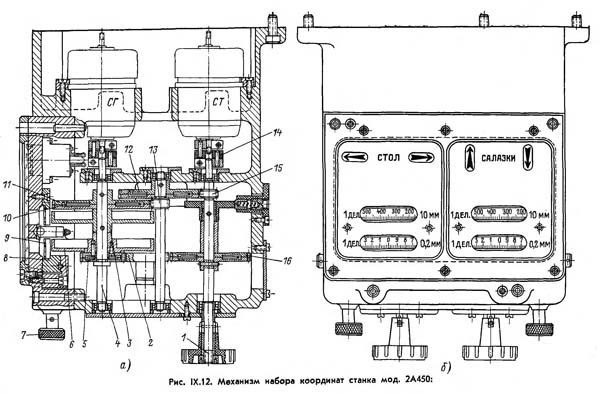
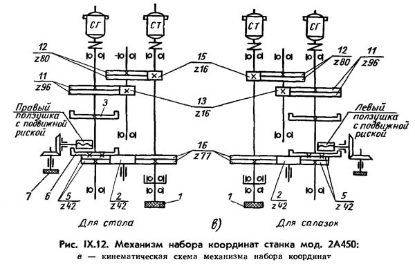
Coordinate set mechanism(Fig. IX.12) is a two-stage gearbox with spur gears 15, 12 and 13, 11, the total gear ratio of which is:
16/80 16/96 = 1/30
The value of the next coordinate is set with a relatively small accuracy on the control panel of the setting device before the start of the movement; this setting can be combined in time with the processing of the previous hole.
The command is executed after pressing a button on the control panel. The specified size and accuracy of execution ensure that the table or sled moves to a position close to the final one. Further movement is performed manually with control over the raster on the screen of the optical device (see Fig. IX.9, a). The mechanism of a set of coordinates (Fig. IX.12) consists of two independent sections, identical in design and controlling: one - the movement of the table, the second - the movement of the sled.
The roller 1 of the size setting is connected by a coupling 14 with the exact selsyn ST, and the roller 4 is connected with the coarse selsyn SG. Limb 6 counting tenths of a millimeter is freely placed on roller 4 and dial 3 counting tens of millimeters is fixed. Limb 6 is connected to limb 3 by gears 5 and 2, 2 and 16, 15 and 12, 13 and 11, the gear ratio of which is equal to:
i = 42/42 42/77 16/80 16/96 = 1/55
One turn of the fine dial 6 corresponds to a movement of 40 mm, and half a turn of the coarse dial 3 corresponds to a movement equal to:
1/2 40 x 55 = 1100 mm
The gears of the mechanism are designed so that in each pair the large gear (16, 12 and 11) consists of two parts, between which a spiral spring 10 is placed, which turns the gear rims in opposite directions and thus selects the gaps in the engagement.
So that the reading on the limbs does not diverge from the reading on the exact scales, after shifting the stroke image with an optical wedge 8 (Fig. IX.9), it is necessary to shift the targeting mark of the reading plate 9 (Fig. IX.12, c) by the same amount. To do this, by rotating the handle (head) 7, slider 8 is moved through a pair of conical wheels, with which plate 9 is fastened. 300
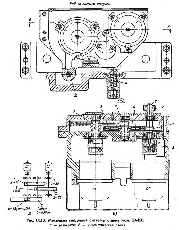
Tracking system mechanism(Fig. IX.13) is a two-stage gearbox with spur gears 7 and 4, 3 and 2, having a total gear ratio of 1: 30. The drive roller 5 on one side through the rack wheel 6 is connected to the rail 9 of the table or sled, with the other side through coupling 8 with precise synchro ST.
The output roller 1 is connected to a coarse selsyn ST. The connection between the mechanism of a set of coordinates and tracking systems is carried out electrically. The servo system gearbox is attached to the slide (frame) through the hinge pin 10 and the spring 11 presses the pinion wheel against the rail, thus choosing the gap.
The table and slide have one flat guide and one prismatic rolling guide. On the lower and side planes of the table are mounted: a coarse scale ruler, clamp tapes, an optical scale ruler, a correction ruler, a table movement rail and a tracking system rail.
Screens of longitudinal and transverse movements, a preliminary set of coordinates mechanism and a machine control panel are mounted on the front wall of the slide.
Projection optics devices, table and sled movement reducers, and a table clamp reducer are mounted inside the sled. On the rear tail part of the sled, motors for moving the table and the sled and a mechanism for the tracking system for moving the table are mounted. In the extreme positions of the table and sled, the motors for their movement are automatically switched off.
The described design of the machine has been improved compared to the previous model of the machine 2A450. A new electrical circuit has been developed that allows you to simultaneously move the table and the sled, the method of final bringing the given coordinate to the preliminary set has been revised, the optical circuit has been improved, the spindle rotation drive and the method of its stepless regulation have been revised, and some other improvements have been made.
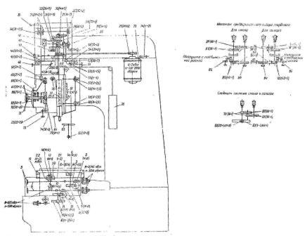
2A450 Wiring diagram of a jig boring machine

Schematic diagram of the 2A450 machine without a table and sled motion control system
- A - ammeter
- VV - input switch
- VK - spindle stroke limiter
- 1VK1, 1VK2, 2VK1, 2VK2 - table and sled travel stops
- 6VK - slide travel limiter
- KE - magnetic starter for switching on EMU
- 1K - magnetic starter of zero protection
- KT - magnetic brake starter
- KP1 - magnetic starter of the 1st stage of the spindle start
- KP2 - magnetic starter of the 2nd stage of the spindle start
- KZSH - magnetic starter of spindle deceleration
- 1KZ and 2KZ - magnetic table and sled clamp starters
- 1KO and 2KO - magnetic starters wringing the table and sled
- 1KU - general stop button
- 2KU - work preparation button
- ZKU - optics lighting button
- 4KU - spindle stop button
- 5KU - spindle start button
- 6KU - slow rotation button
- TKU, 8KU - button for turning on the clamp and wringing out the table and sled
- 9KU - table and sled start button
- 11KU, 12KU - buttons for changing the spindle speed
- 1L1, 2L1 - optics illumination lamps
- lL4, 2L4 - illumination lamps for limbs of preliminary set of coordinates
- 4L, 5L - lamps for backlighting machine limbs
- 7L - sled ruler backlight
- 1L2, 1L3, 2L2, 2L3 - signaling lamps for pressing and clamping the table and sled
- ЗЛ - signaling lamp for switching on the voltage
- 1L5, 1L6 - traffic direction signaling lamps
- 6L - Point Finder Microscope Lamp
- LO - local lighting lamp
- OSD - winding synchronous motor
- OVDSh - motor excitation winding DSh
- RT - thermal relays
- RO - relay lighting optics
- RMV - relay of slow rotation of the spindle
- 1РВ, 2РВ - forward movement relay - slide, right - table
- 1РН, 2РН - reverse movement relay - slide, left - table
- 1RBP, 2RBP - relay for fast movement of the table and sled
- 1РЗ, 2РЗ - table and sled clamp memory relay
- 1ROK, 2ROK - coordinates processing relay
- RVO - optics lighting time relay
- RVP - time relay of the 2nd stage of starting and braking of the spindle
- 1РВВ, 2РВВ - clamp and spin time relay
- RVD - engine excitation regulator DSh
- 1TP - control circuit transformer
- 2TP - optics lighting transformer
- MU - magnetic amplifier
- 2P - local lighting switch
Electrical diagram of the machine and the system of preliminary set of coordinates
Wiring diagram machine (Fig. IX.10 and IX.11) includes electric drives of the spindle, table and sled, clamping mechanisms, cooling and provides illumination of the optics of the machine, blocking and protecting its units during various modes work.
The rotation of the boring spindle, the movements of the table and sled are made from DC motors, and the clamping of the table and sled and the drive of the cooling pump are from asynchronous electric motors. To power DC motors, there are magnetic and electric machine amplifiers.
The electrical circuit provides the inclusion of spindle rotation (Fig. IX.10, a), its shutdown with braking, stepless change in the number of revolutions, as well as slow rotation with a "creeping" speed.
The spindle is started in two steps using magnetic starters and is controlled by a time relay. The slow rotation of the spindle can only be enabled after it has stopped. The spindle load is controlled by an ammeter. The spindle travel is limited by a limit switch.
Table and sled electric drives. The electrical circuit of the machine provides the following modes of operation: a preliminary set of coordinates from a fixed base; set of coordinates by the operator (without preliminary set); working feed of the table and sled during milling and their fast movements.
The movement of the table and sled can occur simultaneously, due to the presence of two completely identical schemes with duplication of equipment.
The required mode of operation of the machine is set by switches on the control panel. The coordinate setting system ensures the movement of the table and sled by a value previously set on the dials of the mechanism for the preliminary set of coordinates (see Fig. IX.12). At the same time, depending on the direction of the coordinate being set - “Right” or “Left”, “Forward” or “Back”, the corresponding relays are turned on and the signal lights are on.
The coordinate reference system is made on the basis of a tracking system, where non-contact selsyns operating in a transformer mode are used as mismatch meters between the angular positions of the initial (master) and final link.
- 1 In the diagrams before the designation of devices and machines, the number 1 in front means that the device refers to the table drive, the number 2 - to the sled
- In the description, for simplification, the symbols relating only to the table will be given.
2A450 Electric circuit for controlling the movements of the table and sled of the machine
![]()
Schematic diagram of the movement control of the table and sled of the machine 2a450
- 1VG, 2VG - germanium rectifiers
- VSV, VSU - selenium rectifiers
- 1EI, 2E1 - anti-oscillatory capacitors feedback
- 1E2, 2E2 - higher harmonic filtering capacitors
- 1KO, 2KO - compensating windings EMU
- OV1D, OV2D - excitation windings of electric motors D1 and D2
- OB1T, OB2T - excitation windings of tachogenerators 1TG and 2TG
- 10U1, 10U11, 20U1, 20U11 - control windings 1EMU and 2EMU
- 1П - switch for switching on the preliminary set of coordinates
- 5PP - fuse
- 1RSD, 2RSD - table and sled speed controllers
- 1RFCh, 2RFCh - phase sensitive relays
- 1RP1, 2RP1 - relay for switching from coarse selsyn to fine
- 1RT, 2RT - thermal relays
- 1STO, 2STO - selenium current limiting posts
- 1C1, 2C1 - braking resistors
- 1C2, 2C2 - anti-oscillatory feedback resistance
- 1C3, 2СЗ - protective resistances
- 1S4, 2S4 - adjusting resistances
- 1С5, 2С5 - resistance of fast movements
- 1C5, 2C6 - movement resistance on the precise synchro
- CMEA - economic resistance
- 1SDG - 1SDT - selsyns of coarse and fine counting, setting the movement of the table
- 2SDG, 2SDT - selsyns of coarse and fine reading, setting the movement of the sled
- 1SPG, 1SPT - selsyns of coarse and fine counting, controlling the movement of the table
- 2SPG, 2SPT - coarse and fine reading selsyns that control the movement of the sled
- SI - voltage stabilizer
- 1T1, 2T1 - isolation transformers
- 5T - step-down transformer
- 1ShKO, 2ShKO - shunts of compensation windings
The tracking system is made here two-channel, i.e. there are two selsyn-sensors and two selsyn-receivers for a set of each of the coordinates (Fig. IX.12, c and IX.13). However, a pair of synchros (sensor and receiver) is included in the system with a gear ratio of 1: 1 and forms an accurate reading of the TO of the system, which serves to ensure matching at small mismatch angles. Another pair of selsyns is included in the system through gearboxes and forms a rough reading of the GO, which ensures coordination at large mismatch angles. Selsyns GO have only one stable coordinated position at a mismatch angle of up to 180 °.
It is impossible to apply TO and GO errors to the input of the voltage amplifier at the same time, since they will distort each other and, at certain values, may be in antiphase. To eliminate the possibility of this, a relay selector of coarse and fine readings was introduced into the circuit, which consists of a VG11 rectifier (see Fig. IX.10B), a polarized relay RP and a relay RP1.
At large mismatch angles, control is a function of the voltage of the LNG coarse selsyn (Fig. IX. 10b), and at small angles, it is a function of the fine selsyn of the SPT. The selector input is supplied with a coarse synchro voltage, regulated by the resistance C27 (Fig. IX.10c). When this voltage decreases, the RP relay opens its contacts, which turn off the RP1 relay. Contacts RP1 turn off the signal of fast movement and connect the circuit of precise synchros. In this case, instead of the coarse selsyn voltage, the fine selsyn voltage will be applied to the input of the phase-sensitive device.
To amplify the tracking error signal, as well as the signal from the stabilizing devices, both in terms of voltage and power, to the values \u200b\u200bnecessary for the operation of the executive engine, an electronic amplifier 1EU (Fig. IX.10b and 11) and an electric machine amplifier 1EMU (Fig. IX.106).
At the output of the electronic amplifier, the control windings 10U1 and 10UP of the electric machine amplifier 1EMU are connected, which feeds the armature winding of the electric motor D1 of the table drive.
At the input of the electronic amplifier 1EU, in the presence of mismatch angles, the difference in the voltage of the driving signal, taken from the winding of the selsyn-sensor 1SDT or transformer 1T1, and the voltage of the tachogenerator 1T G.
With an increase in the voltage of the driving signal, the voltage at the input of the 1EU increases, the excitation and voltage of the 1EMU increase, as a result of which the number of revolutions of the electric motor D1 increases. With a decrease in the setting signal, the number of revolutions of the electric motor D1 decreases accordingly.
With a constant value of the setting signal, as a result of an increase in load, etc., the number of revolutions of the electric motor will decrease; this reduces the voltage of the tachogenerator and increases the voltage at the input of the 1EU, as a result of which the excitation of the YuMU and the voltage increase, and the speed of the electric motor will be restored.
So supported constant speed table movement.
The excitation windings of the electric motor D1 - OV1D and the tachogenerator OB1T are powered by the voltage of the selenium rectifier VSV.
To reduce the heating of electric motors when they are turned off, the resistance of the SEV is introduced in series with the excitation windings.
Electronic amplifiers are powered by stabilized voltage.
To significantly increase the speed of the D1 engine, 1C5 resistance is switched on in series with the excitation winding of the tachogenerator, and for a slight increase in speed when operating from an accurate selsyn, 1C6 resistance.
The direction of movement of the table or sled when working with a preliminary set of coordinates is determined by the sign of the angle of mismatch, i.e., the direction of rotation of the rotors of the master selsyns 1SDT, 1SDG. When the operator turns these selsyns, a mismatch voltage appears on their windings, which is fed to the input of the phase-sensitive unit (Fig. IX.10B).
Depending on the position of the relay RP and RP1, one or another voltage is supplied to the grid of the 6N2P lamp. The anode circuit of the 6N2P lamp is powered by a stabilized alternating current voltage. When different types of mismatch voltages are switched on to its grids (coincident in phase with the voltage of the anode circuit or shifted by 180 °), one or another contact of the phase-sensitive relay 1РФЧ closes (Fig. IX.10, b, c). The 1РВЧ relay prepares the 1РВ relay coil circuit (Fig. IX.10, b) for moving the table to the right or the 1РН relay coil circuit to the left.
The direction of movement is indicated by signal lamps. The electrical circuit provides for the possibility of turning on the electric motors of the table and sled only after they are pressed out. Clamping and spinning occur by pressing a button on the control panel.
With the help of a device for preliminary set of coordinates, the counting of movements when setting coordinates is set with an accuracy of 0.1 mm. Mining is carried out to a point within 0.5 mm to a given coordinate. Precise installation requires manual movement with control over the screens.
When manually controlling the drive for moving the table and sled, the operator uses the 1RSD regulator (Fig. IX.10, b). To quickly move the table, the 1RSD regulator is placed in the extreme position, which leads to a decrease in the voltage of the tachogenerator, and, consequently, to an increase in the speed of rotation of the electric motor D1. In extreme positions, the movement of the table is limited by limit switches.
2A450 Diagram of a phase-sensitive unit and an electronic amplifier

Scheme of the phase-sensitive block
- TRF - isolating transformer
- C21, C22 - grid resistances
- C23, C24 - divider resistance
- C25 - balancing resistance
- C26 - sensitivity regulator for the input of the precise selsyn
- C27 - selector sensitivity regulator
- RP - selector relay
- RP1 - signal multiplication relay selector relay
- RFCh - phase-sensitive relay
- E10, E11, E12 - filter capacitors
- EL11 - double triode
- VGP - germanium selector rectifier
2A450 jig boring machine. Video.
Technical characteristics of the jig boring machine 2A450
| Parameter name | 2A450 | |
|---|---|---|
| Main parameters of the machine | ||
| Working surface of the table, mm | 1100 x 630 | |
| The largest mass of the processed product, kg | 600 | |
| The largest drilling diameter in steel 45, mm | 30 | |
| The largest boring diameter in steel 45, mm | 250 | |
| The smallest and largest distance from the end of the spindle to the table, mm | 250...750 | |
| The greatest movement of the table, mm | 1000 x 630 | |
| The greatest vertical (travel) movement of the spindle (manual, mechanical), mm | 250 | |
| The greatest vertical movement of the headstock (adjusting), mm | 250 | |
| Distance from the spindle axis to the rack (spindle overhang), mm | 710 | |
| Spindle inner taper | Special | |
| Largest taper of the tool to be clamped | Morse 4 | |
| Attaching the spindle box to the rails | manual | |
| Feed mechanism overload protection | there is | |
| Number of T-slots on the table | 7 | |
| The value of the accelerated movement of the table, mm / min | 1200 | |
| Limits of working feeds during milling, mm/min | 30...200 | |
| The price of dividing the raster grid for setting the coordinates, mm | 0,002 | |
| Spindle speed (b/s regulation), rpm | 50...2000 | |
| Limits of working feeds per spindle revolution (b / s regulation), mm | 0,03...0,16 | |
| Drive unit | ||
| Number of electric motors on the machine | 6 | |
| Main drive electric motor Power, kW | 4,5 | |
| Main drive electric motor, rpm | 1800 | |
| Table movement drive. power, kWt | 0,245 | |
| Table movement drive, rpm | 3600 | |
| Slider movement drive. power, kWt | 0,245 | |
| Slider movement drive, rpm | 3600 | |
It is intended for processing holes with the arrangement of axes, the dimensions between which are given in a rectangular coordinate system.
Along with boring on the machine, if necessary, drilling, light (fine) milling, marking and checking linear dimensions, in particular center distances, can be performed.
Using the rotary tables and other accessories supplied with the machine, it is also possible to machine holes specified in the polar coordinate system, inclined and mutually perpendicular holes and turning end surfaces.
The machine is suitable for work both in tool shops and in production shops for precise machining of parts without special equipment.
Technical characteristics of the machine 2A450 this is the main indicator of the suitability of the machine to perform certain work. For jig boring machines, the main characteristics are:
- table top size
- largest drilling processing diameter
- largest turning diameter
- distance from the end of the spindle to the working surface of the table
- spindle revolutions per minute
Below is a table with the technical characteristics of the 2A450 screw-cutting lathe. In more detail, the technical characteristics of the screw-cutting lathe can be found in the passport of the machine 2A450
| Name of parameters | Unit. | Quantities |
| Working surface of the table (LxW) | mm | |
| The greatest longitudinal movement of the table | ||
| The greatest transverse movement of the table | ||
| Distance from the end of the spindle to the working surface of the table | mm | 250...750 |
| Maximum spindle travel | ||
| Departure of a spindle from a rack | ||
| Spindle speed limits (stepless) | rpm | 50...2000 |
| Feed limits per spindle revolution | ||
| Maximum drilling diameter in steel in solid material | ||
| Large bore diameter | ||
| Permissible workpiece weight when installed on the machine table | ||
| The amount of rapid movement of the table and sled | ||
| The amount of movement of the product during milling | ||
| Spindle motor power | ||
| Spindle motor speed | ||
| Machine dimensions | 2670x3305x1266 |
|
| Machine weight |
Attention! The specifications in the above table are for reference only. Machine tools produced by different manufacturers and in different years may have characteristics that differ from those given in the table.
Passport of the machine 2A450
This instruction manual " Passport of the machine 2A450"Contains information necessary for both the maintenance personnel of this machine and the employee directly involved in the work on this machine. This manual is an electronic version in PDF format, the original paper version. This documentation contains the Passport and the Manual (instruction) for operating the machine 2A450.
- Purpose of the machine
- Technical characteristics of the machine
- Requirements for the operating conditions of the machine
- Transportation of the machine
- Installation of the machine and connection to the electrical network
- Passport of jig boring machine
- Description of the kinematic diagram of the machine
- Launch preparation
- Machine control
- Optical coordinate reference system
- Machine safety
You can download the passport of the 2A450 jig boring machine in good quality from the link below.
Passport of the machine 2A450, coordinate boring. Free download.
Kinematic diagram of the machine 2A450"
You can download the kinematic diagram of the 2A450 jig boring machine in good quality from the link below.
Kinematic diagram of the machine 2A450. Free download.
Electrical diagram of the machine 2A450
Below is a sketch of one documentation page" Scheme of the machine 2A450"
You can download for free the electrical circuit of the 2A450 jig boring machine in good quality from the link below:
Electrical diagram of the machine 2A450, jig boring. Free download.
You can view more additional information on "Machine 2A450" at the link below:
Jig boring machine 2A450, 2D450, 2E450, 2E450AF30, 2450 is used for work in tool shops (processing of conductors and fixtures) and in production shops for precision machining of parts without special equipment. The machine is equipped with optical screen reading devices that allow you to count the integer and fractional parts of the coordinate size. Under normal operating conditions, the machine ensures the accuracy of setting the center-to-center distances in a rectangular coordinate system - 0.004 mm.
Machine 2A450 - single-column type, has a rectangular table with longitudinal and transverse movement. The adjusting movement of the spindle head is provided.
The working and accelerated movement of the table in the longitudinal and transverse directions are carried out by electric drives with a wide range of regulation, which make it possible to increase the rigidity and productivity of the machine during milling.
Precise setting of the table to a given coordinate is done manually, with a handwheel. The machine is equipped with a digital indication device, enabling the operator to set coordinates with a resolution of 0.001 mm.
Spindle rotation is carried out from an adjustable AC electric drive through a three-stage gearbox. Spindle feeds are carried out steplessly using a friction variator. There is a mechanism for automatic shutdown of the spindle feed at a given depth.
The machine is provided with mechanical clamps of the table, sled and manual clamping of the headstock.
****
Machine accuracy class A according to GOST 8-71
Table working surface (length x width), mm 1100x630
The greatest movement of the table, mm:
longitudinal
transverse
lO0O
630
Distance from spindle nose to table surface, mm:
greatest
least
750
250
Distance from the spindle axis to the rack (outreach), mm 710
The largest drilling diameter, mm 30
The largest boring diameter, mm 250
The greatest weight of the processed product, kg 600
Coordinate setting resolution, mm 0.001
Coordinate setting accuracy, mm 0.005
Diameter of universal turning table, mm 440
Diameter of horizontal rotary table, mm 600
Spindle bore taper (special) 5°
The largest taper of the Morse tool No. A
The greatest movement of the spindle, mm 250
The greatest movement of the spindle head, mm 250
Spindle RPM limits 50-2000
Spindle feed limits, mm/rev. 0.03-0.16
Table travel speed, mm/min working (during milling):
working (when milling)
accelerated
Machine dimensions, including table and slide travel (length x width x height), mm
Machine weight (without electrical cabinet and accessories), kg
20..315
1200
2670 x 3305 x 2660
7300
Modifications
- 2450, 2L450A - 1100 x 630 coordinate boring machine with an optical coordinate system along the X and Y axes
- 2A450AF10, 2D450AF10 - jig boring machine with a digital indication device along the X and Y axes (DRO). Electronic flywheel mode.
- 2D450AF11-01, 2L450AF11-01 - jig boring machine with a digital indication device along the X, Y and Z axes and a preliminary set of coordinates along the X and Y axes. There is a servo positioning mode and an electronic flywheel mode with a table displacement resolution of 0.001 and 0.01 mm .
- 2L450A, 2L450AF11-015, 2L450AF4-02 - jig boring machine with a universal rotary dividing table with a faceplate diameter of 400 mm.
- 2E450AF30 - a jig boring machine with a numerical control device (CNC) with the ability to set a processing program in an interactive mode along the X and Y axes and digital indication of coordinates along the Z axis.
- 2450A, 2D450, 2D450A, 2E450A - 1120 x 630 coordinate boring machine with an optical coordinate system along the X and Y axes
- 2450AF1, 2D450AF1, 2E450AF1 - jig boring machine with digital indication device (DRO)
- 2450AF2, 2D450AMF2, 2E450AMF4, 2L450AF4-02 - jig boring machine with numerical control (CNC)
- 2E450AF4, 2E450AMF4 - a jig boring machine with a numerical control device (CNC) with contouring along the X, Y and Z axes. The graphic monitor allows you to debug programs without moving along the axes. Part programs can be prepared online with standard text files or automated systems.


What prayers should be read in the morning and evening
Hegumen Dionysius (Shlenov)
Temple of the Life-Giving Trinity on the Sparrow Hills of the Revelation of John the Theologian read adapted
The miracle of the prayer “Our Lady of the Virgin, rejoice The prayer of the mother of God is read 150 times
Can a husband and wife be godparents to a child Can a husband and wife become godparents