Section 3 Control Systems technological equipment
Topic 3.1 Classification of equipment control systems
1. Varieties of control systems for technological equipment
2. Features and characteristics of control systems
3. Structure of equipment control systems
1.Control - this is a purposeful impact on any object or ongoing process in order to qualitatively or quantitatively change the parameters and achieve certain goals.
Software or Software - Definition, Types, Uses
It is a term used in the technical field to define the computer applications used to control and monitor any electronic system. On the English language This term is generally used for any computer program in any area.
An operating system is a category of software that provides many core features and services to user IT applications. The operating system is the user interface between the user and electronic system which he controls.
Any management of a technological object includes the following components:
Collection of primary information about the managed object (information about the product, equipment and processing methods recorded in the UE), secondary information (information obtained during management)
Processing the information received (performing the necessary calculations, data analysis, checking conditions, etc.);
The operating system allows you to write and read information from the storage medium, send and receive information through network interfaces, access attached video cameras, print documents, etc. Software is software that requires the use operating system. The software cannot directly access the hardware, but only through the functions provided by the operating system.
§2.4. Formation of a drilling file to be sent to the microcontroller
Software applications can be spreadsheets or software for text editing, video editing, media playback, web browsing, control technology technological processes. Site Terms: The content of the site, regardless of where it is located on the site, and regardless of its type, may be used solely for personal use.
Conclusions and adoption of necessary decisions;
Providing control actions.
CNC most fully and efficiently implements all components automatic control. CNC gives flexibility to technological equipment, since restructuring it to a new type of technological process, products comes down to reconfiguring the equipment and loading the CNC with new control programs with overwriting new parameters in data arrays.
Any use of content posted on the site by third parties for purposes other than personal use can only be made with the prior written consent of the site. It is forbidden to copy, extract, reproduce, publish, transmit, sell, in part, in whole or modify the content of this site or any part thereof, made for purposes other than personal use, with the following exceptions.
Which digital display software is the most suitable for my business?
It is allowed to reproduce fragments of articles published without the permission of the site. . You are about to dig into the world of digital displays. You are aware of your advantages and you intend to use them. The next step is to choose the most used, valuable and up-to-date digital display software.
STO classification.
By structure: single stage and two stage.
1. Single-stage - the central control center (CDP) has direct communication lines and telemechanics channels with all production facilities and complexes.
2. Two-stage - communication is carried out through intermediate points (operator's or dispatcher's).
§1.1. Equipment with numerical control. Purposes, functions, existing solutions and models
Increasing the number of digital outdoor advertising creates more user-friendly software features. You will need the hardware that suits your needs, depending on the digital display you choose. In short, the software you choose will be the deciding factor for your reporting to users. Your message must be effective or your digital advertising campaign will fail.
By nature of use:
1. for prompt intervention in the course of the process;
2. to improve the organization of management;
3. to create new schemes and designs, improve machines and complexes.
According to the degree of centralization:
1. centralized (characterized by the presence in the system of a single command apparatus, with the help of which the control action is carried out on the working bodies of the machine, which determine the required sequence, speed, feed, amount of movement.)
Let's take a look at what features and functions you need to use to work with a digital display in order to make an intelligent decision to buy it. Will you be able to translate high-quality images, photos and other content onto the screen? If you want to deliver content to a specific audience at a specific point in time, the software vendor must set up client scheduling capabilities in the product to display specific content based on incoming data.
If the weather is cold or wet, the menu responds with hot chili sauce or coffee. Otherwise, when the field is 30 degrees, the menu may display the contents of cold drinks or frozen cream. Custom digital display software can greatly enhance the effectiveness of any digital marketing campaign according to customer needs.
Advantages- compactness, short length of communication lines.
Flaws- significant costs for re-equipment due to changes in the design of the command apparatus.
Example: crankshaft of a turret lathe;
2. decentralized (characterized by the absence of a command device, the control action is formed by each individual working body, using stops and limit switches). All operations in such systems are performed sequentially.
The same ideas apply to retail. The system also controls the types of products that are in demand during the changing season. The retail giant is working with weather and store sales in response to store-level sales and local digital advertising.
If a particular region is expected heavy rain, umbrellas are offered. If snow is expected, snowplows are provided. If your customers' needs change like air, trade planning options are a must for the software of your choice.
Advantages- the possibility of organizing management of a significant number of objects; exclusion of subsequent signals in case of failure of the previous ones, fast overshoot.
Flaws - a large length of communication lines (increase in error), due to the adjustment and reinstallation of the stops, a significant investment of time.
They say parameters are very important. In the field of digital displays, this is true. If you use great software, but the network that transmits it is weak, it loses its meaning. The network used by your software must provide user data without any inconvenience.
Assigned data indicates that your content was presented to the right audience at the right time with specific, future purchase requirements. We will talk about it later. Now let's look at the network settings and presentation.
Example: robotic complex (RTK) of the servo drive.
For traffic control:
1. travel (position control using travel switches, stops, cams);
2. command (time control with the help of command devices and PMK);
By software type: magnetic tapes and disks; punched cards and punched tapes; LAN - local computer networks; copiers and templates; cams and flywheels.
Why presentation is so important: Most digital ads today aren't used on large screens. Mobile phones are becoming an integral part of our identity, and digital advertising campaigns use data from digital screens for smartphones.
When creating a product-focused campaign, it must reach the customers of those products where they are. Because two-thirds of Americans use mobile phones, users can access at any time. Not wanting to receive a billion dollar strike, the trader offered "special" messages sent to customers on smartphones. Customers were offered a special price when shopping and picking up items in the store.
By element base: electric; mechanical; hydraulic and pneumatic.
2. Tasks of the STO: 1) Ensuring the required actions of executive mechanisms.
2) Ensuring the specified modes.
3) Ensuring the required parameters of the production facility.
4) Implementation of auxiliary parameters.
Requirements.
However, in 80% of cases, the goods were in other stores. By offering delivery options from other stores, the number of sales increased significantly. If you use a secure and reliable data network, consumers know that their customers are being offered best opportunities at the right time and in the right place.
Digital displays need to be more than just a standalone marketing campaign that usually changes images and text. Thirty years ago it was normal to create digital screens. There are many more options available. Whether you want to use social media feeds, interactive media, or touch screens, you need software with advanced settings. The ability of the software to integrate with third party data providers is very important.
1) Ensuring high mobility.
2) Ensuring the implementation of complex functioning tasks.
3) Simple design and low cost.
4) Opportunity remote control.
5) Possibility of self-regulation.
STO teams.
Technological - provided by the technical process.
Cyclic - change of parameters, tool, coolant, reverse.
Imagine software that allows your customers to "feel" the power of digital displays. The decision was made to use sensors that respond to the upcoming train on a digital display on the Stockholm metro platform. As the train approached the platform, the sensors on the screen were activated and the image of the digital woman revived, her hair blinding.
The hair is blown and your mind reacts to it. Think about customer service when deciding which software to choose. You will probably receive many questions that require careful answers and explanations. Some companies provide their customers with a three-page questionnaire to better understand what their marketing campaign is about.
Service - performed using logical operations.
Classification of systems, according to the nature of the information recorded on the program carrier; continuous, discrete and discrete-continuous systems.
In continuous systems, the program is recorded continuously. If a phase modulation system is used, then the program is represented by a sinusoidal voltage, the phase of which is proportional to the programmed movements; in systems with amplitude modulation, the displacements are proportional to the amplitude of this voltage.
The questionnaire will help you decide what the buyer expects from a digital display. Once this is established, vendors may recommend necessary equipment and software. This is customer service. Most companies or organizations don't understand the process itself when looking for digital technologies or software vendors, so it's important to find a company that will give you time and help you understand the processes.
There are two types of digital software available for you: - Cloud-based digital screen software - In-room digital screen software. Provides a distinction between the two: The clouds used by digital display software are an invisible solution. All your information is stored in the cloud.
Table 1 - Examples of the application of the SMS
| Designation | Definition |
|
| Tracking systems (cycle, copy) |
||
| Numerical program control according to the program specified in coded form In short, the digital display is in your store and the information sent directly comes from a content management system. This means content is stored in the cloud and software updates are also controlled by the clouds. In the case of indoor digital display software, your store also requires a display with information sent only from the back office or company headquarters. Information is sent individually to each store. In this case, the software resides on your server and you control its updates. Which solution is best for you? You are less likely to find a company that does not opt for cloud solutions. Companies want software to be automatically updated, which does not require any Maintenance, which could help, and which would not require server cabinets. Most companies are looking for software with a low learning curve that will be able to pull and offer a variety of work patterns. |
||
| Operational CNC system with manual programming on the control panel |
||
| Control system with microcomputer or microprocessor and software implementation of algorithms |
||
| System program control a group of machines from a common computer that stores and distributes programs upon request from machine control devices Automatic machine control systemsIn this case, the cloud software is the best choice. Deciding on the best software doesn't have to be difficult. It should suit your needs and budget. Since all software prices are different, the cost need not be the deciding factor. The most important thing is functionality. Ask yourself the following questions: What message do you want to convey? Do you want your audience to interact? You need more advanced support solutions social networks or other interactive media channels? Do you want to integrate a third party data provider? |
||
| Personal or professional computer |
||
| A programmable command device is a device for performing logic functions, including relay automation. May be part of the CNC |
||
| Local computing network |
||
| Industrial Automated LAN Protocol |
||
| Adaptive cutting data control or error compensation. Can be executed algorithmically in the CNC system |
||
In discrete (impulse) systems, information about displacements is given by the corresponding number of impulses. If the movement mechanism is equipped with a pulse sensor and a counting circuit is used to account for the movement, then the system is called counting-pulse. If the executive device is stepper motor, then the system is called step-pulse.
In pulse-phase CNC devices, the summation of the pulses specified by the program is carried out in a phase converter, the output signal of which in the form of an AC voltage phase shift angle is proportional to the number of program pulses.
Classification of systems by changing the processing modes of the CNC system
By changing the processing modes, CNC systems are divided into cyclic, program and adaptive.
Cyclic systems carry out movements with repetitive cycles. They use cam, hardware, microprogram and programmable control. With cam control, plug-in panels are used to set the modes, hardware control is carried out using relay-contact or non-contact equipment. For microprogram control, microcommand memory devices are used, and programmable control of processing modes is based on the use of programmable logic tools.
In CNC software systems, the change in processing modes is carried out by software using a program carrier or computer memory.
The use of adaptive control allows you to automatically change the processing mode, regardless of the program.
Numerical control provides control over several coordinates, so it is widely used on multi-operation machines (machining centers) with automatic tool and workpiece change.
3. All SMSs include the following nodes (Figure 37): a reader designed to enter a control program from a program carrier (CS); input panel (PV); which is designed to enter the control program using the keyboard, as well as to assign operating modes, issue one-time commands and indicate the control of the device status; input node (UVV), which provides the choice of input mode, machine and device control mode, calling automatic cycles by a special G80 command with integration into cycles of actual parameters, control of the tape drive in start-stop mode during the processing of the control program (CP) and rewind control tape to the beginning of the program, decoding the addresses of the commands, temporary storage of their contents and entering the contents of the commands at the decrypted address into the corresponding memory registers. In addition, this unit controls the tape drive during the N frame search specified on the
Figure 37 - Structural diagram of a typical positional CNC
The correction console (PC) is designed for typing and storing corrections at specified addresses. The correction node (UK) provides sequential reading of digital information installed on the switches, input of the read information with normalization upon request in the UE to the corresponding addresses (addresses of tools or coordinates).
The display panel (PI) provides an indication of information on the screen at the addresses involved (line by line or by pages) and is a ray tube, on the left side of which the raster lines indicate the actual position of the working bodies, and on the right side - the set values in the UE. The indication panel can operate in working and test (without testing) modes, which makes it possible to obtain the necessary information. The indication panel together with the input panel is a video monitor.
The speed node (SS) provides control of speeds according to the current coordinates, control of braking and selection of the direction of movement.
The random access memory node (RAM) has a memory for storing input information and information of the results of calculations during processing. In addition, the UOP has a ROM for storing the composition of automatic cycles with addresses. G81 - G89.
A service node (SO) is a specialized microprocessor that processes geometric information, i.e. mismatch angle calculation for all controlled coordinates, performs the functions of a timer, controls the display panel.
The Sensor Unit (SM) is designed to convert the position sensor signals into the CNC code, power the sensors and amplify the signals.
The External Connector Block (EBB) is a standard interface in the form of an adapter or a microcontroller. Provides communication between the CNC and the electro-automatic devices of the machine and their control. The BRV is designed for decoding, generating and distributing control signals to actuators, as well as for collecting and storing information on the state of the object, status signals of working bodies, and readiness signals.
Topic 3.2 Numerical control systems industrial equipment
1. CNC classification
2. Structure of numerical control systems
1. Numerical control system - a complex of devices and equipment, including: CNC; control object; electroautomatic devices that directly control the nodes of the object; equipment and tools; software and mathematical support; means of control.
CNC can be classified according to various criteria.
Classification of systems according to the features of the structure of the CNC system: contour and combined CNC systems
CNC contouring systems allow processing curved surfaces during milling, turning, grinding and other types of metalworking. These systems program the path of the cutting tool, which is why they are often referred to as motion control systems.
Combined CNC systems are a combination of positional and contour and are also called universal. They are used in multi-operation machines where position-contouring control is required.
When designating a model of a CNC machine tool equipped with a positional system, the index “F 2” is added to it, equipped with a contour system - the index “F Z” and combined - the index “F 4”. The index "Ф 1" in the designation of the machine model indicates that the machine is equipped with digital indication and manual control.
Positional CNC systems
CNC systems for metal-cutting machines are classified according to various criteria. According to the type of working movements of the machine tool, CNC systems can be divided into positional, contour and combined.
Positional CNC systems allow relative movement of the tool and workpiece from one point (position) to another.
Such control is used in drilling, boring and other machines, on which processing is performed after the tool is installed in a given position.
Since the main task for such systems is to move the tool (part) to the specified coordinates, they are also called systems of coordinate control and position control.
2. When developing modern universal CNCs, they strive to give these devices the properties of unification, that is, they are created on the basis of unified nodes that have great functional flexibility. When developing a CNC, they provide for more complete automation of programming, the possibility of embedding a CNC in a control object, which in turn can be embedded in a technological module or a larger technological complex, as well as docking a CNC with other CNCs, CNCs and computers more high rank.
The microcomputers used functional structure and mathematical software are problem-oriented for managing all kinds of technological objects. In a microcomputer, the organization of the computational process and logic operation provides for the processing of control information, data transmission and acceptance of information from the control object in real time.
To simplify the problem orientation, microcomputers and other devices are architecturally, functionally and structurally designed as separate modules. Universal CNC, created on the basis of microcomputers, may include various functional modules.
The microprocessor module (MP) may include a main and auxiliary microprocessors, with the main one processing control and scheduling information, and the auxiliary one working on preparing information. For example, an auxiliary microprocessor works in an automatic programming system, calculates the trajectory of movement by the method of linear-circular interpolation, and the main one processes the control information for all devices. In MP, the method of information exchange is trunk, and the control has a microprogram organization, therefore, MP includes, as a rule, an independent module of microprogram control. The MP may include buffer registers for the convenience of operating with data formats. In addition, MPs can be multi-section, which makes it possible to increase sections and operate with any necessary formats. The control device module (CU) provides the organization of control of CNC devices.
The RAM module (RAM) is designed to store operational information. It may include a stack memory module for organizing all kinds of UE interrupts (“stack” from the English word stack, bale). This module is designed to store data before interrupting the NC. Stack registers store the contents of the counters, data addresses before the interrupt to restore them in the main program after returning from the interrupt (these registers exchange information in the following order: the first address is written, the last is read).
Non-reprogrammable read-only memory (ROM) modules and reprogrammable in the form of a reprogrammable memory device (PROM) are designed to store permanent information.
Buffer memory modules store intermediate information, which makes it possible to exchange packet data, as well as exchange information with devices operating at different speeds.
Adapter-type interface modules are used to communicate with various terminals (indication panel, printer, display, etc.).
Microcontroller modules (MC) control various external devices with general management the central processor.
Interval timer modules are designed to set the time intervals necessary to coordinate the working devices.
Communication modules with the control object include DAC and ADC devices and microcontrollers that control them, which serve to convert the signals of the CNC and electro-automatic devices of the machine into the required form; logical microcontrollers that process commands given to the OS in the microcontroller, the given logical equations for controlling the working bodies are converted into signals that form logical-temporal cycles for controlling electro-automatic devices.
Operating device modules (software adapters) convert information of one kind into information of another kind. Adaptive control modules are designed to collect, process technological information and organize corrective PM.
The block diagram of a typical universal CNC is shown in Figure 38. The device consists of several standard modules.
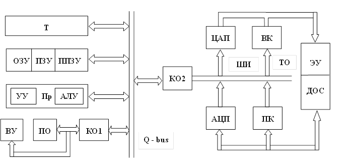
Figure 38 Structural diagram of a typical universal CNC
The processor (PR) is a programmed information converter and includes: an arithmetic logic unit (ALU) used for mathematical processing of information and performing analysis operations; the control device (CU) controls the operation of the processor according to the microprogram algorithm (single-level or multi-level control organization).
Random access memory (RAM) is designed to store control and organizing programs, control programs for controlling the electro-automatic devices of the machine using a programmable controller, for storing the parameters of the technological object and CNC, arrays, service and corrective programs, standard subroutines and other data arrays. The ROM stores programs of standard cycles (procedures), information processing software, standard firmware for controlling various devices using adapters (adapters for controlling drives, an indication panel, etc.), standard programs for controlling other hardware.
PROM serves to record the program of logical microcontrollers that control electro-automatic devices of a technological object, record UE controllers for accessing external devices, record test programs, etc.
Operator console (software) is intended for prompt intervention in the operation of the CNC, i.e., issuing manual control commands, assigning operating modes, viewing the NC, editing it, monitoring the operation of the system, dialogue with the CNC, etc.
To external devices (ED) may include: test control systems, video monitors (devices that include a display and keyboard for loading the CNC with commands or control programs, for calling and viewing them), video terminals, various printing devices (printers), programming consoles in ISO code or in machine oriented language, programming consoles for UE electro-automatic devices of technological equipment, computer systems for automatic programming and computers of a higher rank.
Timer (T) organizes real-time labels necessary to control all devices, including the control object.
Exchange controller type interface (KO1) serves to ensure communication of the CNC with external control devices, control of information exchange with all external devices.
Communication with the control object and the main devices of the object is carried out through a standard interface of the type Q = bus, which is an information exchange management controller, and a 16-bit exchange highway. Exchange controller with the control object (K02) provides control over the exchange of information between the technological object and the CNC using local interface buses (LI) .
Multichannel analog-to-digital converters (ADCs) serve to convert analog signals received from sensors feedback(DSP) , located in the technological object, into the numerical code of the CNC (the number of channels is determined by the number of controlled coordinates).
Digital to Analog Converters (DAC) convert digital codes into analog signals and output them to actuating devices (to electroautomatic devices and drives).
Reception nodes (PC) and output (VK) codes are, as it were, buffer port devices for temporary storage of exchange information, decoding of command addresses, etc.
Technological object (TO) with actuators, electro-automatic devices (EU) and measuring system implements control commands and execution control using DOS.
Topic 3.3 Microprocessor control devices
1. Block diagram of microprocessor devices
2. Programmable microcontrollers
3. Modern tendencies in the development of microcomputer
1. Microcomputers operate with a much smaller number of instructions than large computers, but still it reaches several tens, and at least six bits are required to write them in binary code. Since the addressable volume of ROM is usually several tens of thousands, most often words, the address part of the command must contain digits, i.e., the total "length" of the command must be of the order of digits, which, with the usual "length" of microcomputer memory cells, which is digits, requires three ROM memory cells. This is one of the features of minicomputers and microcomputers, which complicates programming and reduces their resulting speed, which usually does not exceed 150-200 thousand operations such as addition in 1 s.
The microcomputer usually operates with a uniaddress instruction system, in which the address part of the instruction has only one address - the address of the operand that must be transferred to the ALU. The other operand is always in the accumulator; the result of an ALU action on two operands always remains in the accumulator. Commands are of several types: transfer commands, such as "transfer data from RAM to CPU"; commands for arithmetic operations, for example, "add" or "subtract"; commands of logical operations, for example, "compare two numbers"; commands, transition "go", "call", "return"; special commands, such as "stop". Full list commands operated by the microcomputer is given in the accompanying documentation on the computer.
V total the program can have many thousands of instructions that need to be compiled and worked out, and then written to ROM.
The block diagram of a typical sectional MP is shown in Figure 39, the MP consists of two functional modules: a microprogram control unit (MPCU) and an operating unit (OU) built from separate sections. MPUU includes: microinstruction memory (PMK) , which is designed to store received commands; microinstruction sequence controller (KPMK) , the main purpose of which is the implementation of control structures (fragments) found in microinstructions. Thus, the controller provides decryption of the command operation code for accessing the first microcommand of the microprogram, generates the addresses of the following microcommands, both in a linear sequence and conditional or unconditional jumps to the microprogram. In addition, some controllers can store a sign of transitions, manage interrupts at the firmware level. As a rule, the microprocessor kit includes modules for microinstruction sequence controllers for organizing control in various modes.
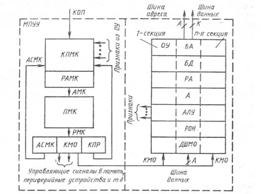
Figure 39 - Structural diagram of a typical sectional microprocessor
MPUU works as follows. The operation code (COP) from the command register is input to the microinstruction sequence controller (KPMK) , and at the output of the microinstruction address register (RAMC) controller, the address of the first microinstruction (AMC) is formed executable firmware. The microinstruction to be implemented in the current microinstruction cycle is read from memory into the microinstruction registers (RMC) .
The microinstruction contains three main fields, whose content is stored in the corresponding nodes:
1) micro-operation code field (CMO) , determining the type of operation performed by one of the microcomputer devices;
2) the field in which the characteristics of the result (CRC) are encoded, coming from OS to the controller and analyzed by the controller when executing conditional jump commands according to the given conditions;
3) a field that contains the address code for generating the address of the next command (ASMK). After executing the read microinstruction, the cycle repeats. The control signals of the microcommands are fed into the corresponding devices of the microcomputer.
OU designed to perform all arithmetic and logical operations. OU assembled from sections of processor elements, each of which contains an arithmetic logic unit (ALU) , general purpose registers (RON) , accumulator (A) - accumulating register, micro-operation decoder (DShMO) , data buffer (DB) and address buffer (BA) , allowing to temporarily store the address (L) and data (D).
One of the features of the OS is vertical partitioning, which requires fewer code transmissions between individual LSIs. Data buses, address buses and micro-operation code are combined into a common backbone. The main advantages of sectional MPs are the possibility of developing a microcomputer with maximum compliance with the structure of the tasks being characterized, the exclusion of redundancy in the structure and bits, and the choice of an arbitrary non-standard capacity. Availability of independent address buses and input and output data buses (address and data buses can be of various formats) makes it possible to organize interfacing with memory and peripheral devices without using multiplexing.
2. Programmable logic microcontrollers (PLMCs) are mainly focused on the implementation of logic functions and are used instead of relay control circuits, i.e. to control semiconductor circuits of electro-automatic devices of technological objects.
PLMCs implement the functions of command devices and microcontrollers and are created on the basis of a microcomputer. These microcomputers can be considered as a universal software-configurable model of a digital control automaton. The possibility of using the PLMC as a universal local control device for various technological processes is achieved by introducing into the PLMC a program that determines the operation algorithm of a particular control object without changing its electrical structure.
The composition of the PLMC, at least, includes a logical microprocessor with a control unit, RAM, remote control for setting and loading the control program and a device for communication with the control object (Figure 40).
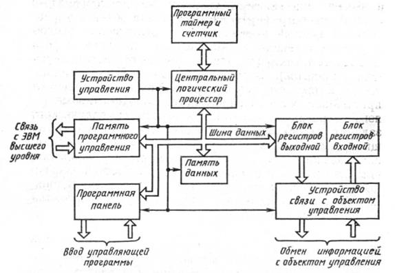
Figure 40 - Programmable logic microcontroller
Figure 40 shows a generalized block diagram of the PLMC, which includes various devices. The central logical processor (CLP) provides logical processing of incoming information in accordance with the program recorded in the program memory and models a specific relay circuit. The control device of the logical processor interrogates all inputs and outputs of the register block, performs a logical comparison of the state of the inputs and outputs, and, based on the results of the comparison, turns on or off certain executive bodies through the scheme of the communication device with the control object. The microcontroller, using a program timer and counter, sequentially, line by line, interrogates (scans) the program memory and, using the CLP, calculates logical functions according to the equations coming from the program memory, and enters the calculated values into the data memory. After the memory poll is over, the microcontroller control unit performs data exchange between the input and output registers of the register block and the data memory. Then the polling of the program memory is repeated from beginning to end.
Thus, the interrogation of the program memory and the exchange of data are periodically repeated during the control process. A single pass of the logical processor throughout the program is called a full memory polling (scanning) cycle, and the time during which this cycle is executed is the cycle time. It characterizes the speed of the microcontroller.
Programmable logic microcontrollers implement relatively simple control functions and have a number of important features. First one of them is that the cycles are continuously repeated in the object control mode. The cycles consist of separate phrases with the following content: "photographing" the state of the object's nodes (polling outputs), processing the data together with the data of the new phrase, and issuing control signals to the executive bodies. "Photographing" the state of the control object at a given moment of time is implemented by inputting signals for polling the state of the object into the corresponding memory cells (receiving responses from the corresponding devices).
Second a feature of PLMC is that for programming they use the simplest specialized, but effective programming languages or languages for the symbolic assignment of control algorithms: simple ones that describe relay contact circuits; logic functions; describing UE with the help of control operators; symbolic encoding, etc.
Third a feature of PLMC is that they can function without permanent maintenance personnel during operation.
3. Wide opportunities for building CNC devices open up the use of microprocessors and minicomputers.
The operation algorithm of a machine or a group of machines depends on the complexity of the configuration of the workpiece, obtaining the required machining accuracy and surface roughness.
To solve the problems of processing parts of a simple configuration with low requirements for accuracy and quality of processing, the functioning algorithm should be quite simple.
The computer processor in this case can be made on the basis of standard blocks from which the control device is created. It reproduces the machine control model, allows parallel execution of operations that implement simple functions. Such control devices are called digital models. The industry produces such CNC systems of the type H22, N3Z, built on microelectronic elements. They are designed to control machine tools and carry out positioning, rectangular and contour (in the plane) control. The restructuring of control algorithms in such systems is impossible.
Microcomputers differ from minicomputers in smaller word length and memory capacity, are implemented on the minimum number of integrated circuits with a high degree of integration and serve to create automatic systems management of simple objects; communication devices with mini-computers, personal computers (PC), etc.
The transition from a multi-crystal microprocessor to a single-crystal and, finally, to a microcomputer placed on a single chip creates the greatest economic effect in the implementation of simplified computers. Multi-chip microprocessors have greater functional completeness, computing power and performance and are most effective in building micro- and mini-computers to control more complex installations and technological processes.
Topic 3.4 Adaptive program control systems
1. Structural diagram of the control system with the adaptation block
2. Functional diagram.
1. The principle of building a control system is based on the fact that the control acts according to a given algorithm, defined by control program in accordance with the primary information about the managed object, the technological process and its parameters, as well as the correction and restructuring of the control algorithm based on the obtained secondary information about the managed object (information about the change in the initial data, the deviation of the actual parameters from the values provided for in the PM, and etc.).
A CNC with such a control organization is called adaptive control system. For such a system, the UE forms the control goal (control algorithms that determine the trajectory of movement of the working bodies, their speeds, as well as other technological parameters and commands based on known information about the control object, workpiece, processing methods, tool, etc.), to which management system should strive. Thus, for adaptive control systems, the recorded UE, which determines the given algorithm for controlling the object and the given parameters, is information about the goals of control, and when the situation in the controlled object changes, such a system will adapt, change the control discipline, taking into account the changed specific conditions, i.e. device management will develop additional management instructions to the existing UE.
In universal CNCs created on the basis of a microcomputer to provide adaptive control, special interface modules are created to connect the control object with the CNC for adaptive control. Moreover, additional modules are also being created in the form of programmable microcontrollers to implement adaptive control in an object. The interface module includes additional analog-to-digital converters for converting sensor signals that measure various technological parameters during control, which are converted into a digital code. In addition, programmable microcontrollers are used to process secondary information and introduce it into the main UE. All the modules listed above are usually controlled from the microcomputer central processor.
In the CNC, built on the basis of a microcomputer, specially developed mathematical and software for organizing adaptive control together with the CNC is stored in the memory.
Figure 41 shows a block diagram of a universal CNC with an adaptation block (adaptation ADC), which provides for the implementation of adaptive control of an object. The universal CNC is built on the basis of the Elektronika-60 microcomputer, which includes the CPU, memory and ROM, the main computer channel. In addition to the adaptation module, the CNC includes the following modules: communication interface with the correction console (CPC), communication interface with printing devices (PU) and electric typewriter (EPM) communication interface with the character information display unit (BOSI) communication interface with the photoreader ( FSU), communication interface with a puncher, communication interface with a cassette tape drive (KNML) U communication interface with a code conversion unit and multiplication units (BU, BPC), a communication interface with a computer of a higher rank.

Figure 41 - Structural diagram of the adaptive control system
The computer channel through the communication interface with the technological object (TO) is connected with external devices through an additional communication line with the control object. Thus, the communication interface with TO controls the exchange of information between the microcomputer and external devices located on the control object.
For communication between the CNC and the control object, the following blocks are used, made in the form of standard modules (blocks serving the working bodies of the control object); block of output and input signals, block of communication with a stepper drive (BSSHP), communication interface with a drive fed and controlled by a thyristor converter with PFM or PWM control; communication module with feedback sensors (ADC DOS), which measure all kinds of technological parameters, therefore, this module can be partially used to obtain secondary information from the control object and process it.
All adaptive CNCs should be used where they provide economic value and justify the initial cost through low redundancy in hardware and standard modules.
Adaptive CNCs used in industrial robots are equipped with special mathematical and software that is recorded in RAM and ROM. The CNC can be equipped with technical vision tools through a special unified interface when adapting to the situation, geometric shape, measuring gripping force for fixing at the moment of gripping, marking workpieces. , relative position, measurement of axial strain during assembly, etc. As vision receptors, cathode ray tubes, integrated matrix-type photodetectors (IFS), charge-coupled matrix devices, dissectors (dissectors are a television tube with an arbitrary scan) can be used beam), matrix strain gauges, etc.
Adaptive CNCs are also widely used in those technological facilities where high requirements are placed on the parameters of technological processes or the parameters of the resulting products. In addition, they are used in cases where the disturbances in the technological process are significant and random in nature, which makes it possible to take into account these deviations in the UE or correct them from the control panel during the control process.
Adaptive control systems differ in ways of adaptation, types of organization of measuring systems, ways of organizing adaptive control and a variety of hardware with which adaptive control is organized. According to the principle of adaptation, adaptive control systems are distinguished: with functional regulation, in which the adaptation process is carried out by regulating parameters that are functionally dependent on deviated values; with extreme regulation, the purpose of which adaptation is to obtain the maximum or minimum result; with optimal control, where many parameters are regulated for the optimal result according to a complex optimality criterion.
Adaptive control systems can differ in ways of controlling the parameters that cause a disturbing effect, and in ways of influencing the control parameters, by means of which, as a rule, adaptation is carried out taking into account new control conditions. Most often, the parameters that are disturbing or regulating are cutting power and force, machining diameter, machining allowance, temperature in the cutting zone, deformation in the machine-tool-tool-workpiece system, cutting tool wear, etc.
Adaptive control systems can differ in the number of control channels, the type and law of control actions.
2. An adaptive CNC with the use of optimal control is built on the basis of a universal CNC with the corresponding additional mathematical and software (Figure 42).

Figure 42 - Functional diagram of the adaptive control system
The functional diagram of the adaptation device includes the following nodes: a node in which the cutting process (PR) takes place and the necessary parameters of the processing process are measured; the elastic system of the machine (USS), which is the actual system machine - fixture - tool - workpiece; feed drive (PP); main drive (GP); circuit synchronization sensor with spindle speed (DS); a sensor that measures the amplitude of oscillations (DC), a current or power sensor (DT), an oscillation sensor amplifier (UDC) a power feedback signal scaling unit and signal compensation generated by the no-load current (BMC) feed rate control signal limiting units (υ s ) and spindle speed (B01, B02); command generator (G); bandpass filter (PF) matching unit (BS) multiplication units (BU1, BU2); extreme oscillation controller by changing the spindle speed (ERC) oscillation controller by changing the feed rate, (RK) logic block for comparing the spindle speed with the specified parameters (BL); power regulator (PM); physical quantities that characterize the feed rate, spindle speed, oscillation amplitude, cutting force (power) and load current during processing.
Based on the complex optimality criterion, the adaptive control system implements several optimal automatic control algorithms with full or partial implementation of the optimality function. This method is carried out by alternately regulating the priority setting according to one or another control algorithm or by joint regulation according to all the necessary parameters of this criterion. An adaptive control system can implement several algorithms for automatic control of process parameters.
Topic 3.5 Flexible manufacturing systems and flexible manufacturing modules
1. Basic terms and definitions of the GPS
2. Flexible automated lines
3. GPS management
4. Current trends in the use of GPS
1. Flexible Manufacturing System (FMS) is a set of various combinations of CNC equipment, robotic technological complexes, flexible production modules, individual units of technological equipment and systems for ensuring their functioning in automatic mode during a given time interval. Any TPS has the property of automated readjustment in the production of products of an arbitrary range within the established limits of the values of their characteristics.
Robotic technological complex (RTK) consists of a unit of technological equipment, an industrial robot and equipment (devices for accumulation, orientation and piece delivery of products). RTK can function autonomously, carrying out multiple processing cycles. If RTCs are designed to work as part of the GPS, then they must have automated readjustment and the ability to be integrated into the system.
Flexible Manufacturing Module (FPM)- this is a unit of technological equipment for the production of products of an arbitrary range within the established limits of the values of their characteristics, autonomously functioning, automatically performing functions related to the production of products, and having the ability to be built into the GPS.
Organizationally, one can distinguish 3 types of GPS: TAL, GAU and GAC.
1) In a flexible automated line ( GAL) technological equipment is located in the accepted sequence of technological operations.
2) Flexible automated section ( GAU) operates on a technological route, which provides for the possibility of changing the sequence of using technological equipment.
3) The composition of the flexible automated workshop (GAC) includes in various combinations flexible automated lines, robotic production lines, flexible automated sections and robotic production lines and sections for the production of products of a given range.
Thus, the GPS is an organizational and technical production system that allows, in the conditions of small-scale, serial and, in some cases, large-scale multi-product production, to replace with minimal cost and in a short time manufactured products for a new one.
In the structure of a typical FMS, three groups of components are needed: technological, management, and pre-production. Each of the indicated groups of components that form the corresponding system (or subsystem) is a man-machine, in which the most labor-intensive functions are performed by the computer equipment included in the system, and the creative functions are performed by designers, technologists and production organizers working on the workstation.
Technologicalsystem is a set of main and auxiliary technological equipment and technological equipment implemented on it production process, which can be machining, assembly, foundry, forging, welding, electroplating, etc. Production functions are carried out using technical means specific to each type of production, built on a modular basis.
At the same time, the following tasks are solved: assembly, storage, transportation and intermediate accumulation of the source material, blanks, semi-finished products and technological equipment; processing and assembly of production facilities; control of blanks, semi-finished products and finished products; control of the parameters of the technological process and the state of the tool, cleaning of production waste (chips, flash, sprues); supply of supporting materials ( lubricant, coolant, molding materials).
Productionflexibility GPS is determined by technological, structural-organizational and parametric flexibility. At the same time, under flexibility understand the adaptability of the GPS to the changes associated with the implementation of the production program. The production system is considered flexible and quickly readjustable without significant costs if the composition of the system components and the composition of information links do not change when the production objects change.
2. Usually machine automatic lines created for the processing of one specific part are very difficult to use for processing new part, even similar in design. Fundamentally new automation tools, which appeared in the form of GPS, made it possible to create for such industries flexible automated lines(GAL).
GALs are designed for group processing of several previously known parts similar in design and manufacturing technology. They consist of reconfigurable modular machines and CNC machines, united by a single automatic transport system. CNC machines are used in such lines for complex processing cycles and, if necessary, implement contour control. The technological equipment of the GAL is located in the accepted sequence of technological operations.
GALs created on the basis of modular machines with interchangeable spindle boxes for processing body parts are widely used.
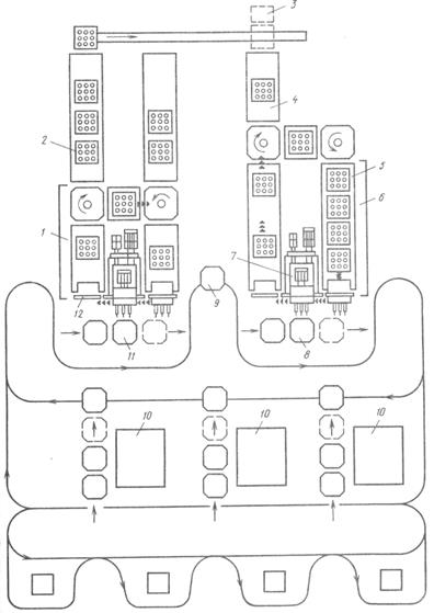 Figure 43 shows an example of such a line, which includes: two sets of unified nodes 1
and 6
for machining, two automatic sections of the spindle box conveyors 2
and 4,
rack 3
for storing spindle boxes not used in a given cycle of work, three positions 10
installation of workpieces on clamping devices-satellites, transport system automatic feeding parts with satellites to work positions 11
and 8
(position 9
for intermediate control of details). Sets of unified nodes have a power table with a gearbox 7
for attaching interchangeable spindle boxes 5
, feeder for power table spindle boxes 12,
a set of conveyor sections and rotary tables. Up to 28 multi-spindle boxes are used on the line, which are transported on satellites at the required period of the processing cycle to the power unit, where they are automatically fixed one by one. When changing over, a new set of boxes is loaded onto the conveyor from the warehouse.
Figure 43 shows an example of such a line, which includes: two sets of unified nodes 1
and 6
for machining, two automatic sections of the spindle box conveyors 2
and 4,
rack 3
for storing spindle boxes not used in a given cycle of work, three positions 10
installation of workpieces on clamping devices-satellites, transport system automatic feeding parts with satellites to work positions 11
and 8
(position 9
for intermediate control of details). Sets of unified nodes have a power table with a gearbox 7
for attaching interchangeable spindle boxes 5
, feeder for power table spindle boxes 12,
a set of conveyor sections and rotary tables. Up to 28 multi-spindle boxes are used on the line, which are transported on satellites at the required period of the processing cycle to the power unit, where they are automatically fixed one by one. When changing over, a new set of boxes is loaded onto the conveyor from the warehouse.
Also, aggregate CNC machines created from sets of unified units (tables various types, automatic tool change mechanisms).
3. GPS management implements complex multifunctional hierarchically built automated systems management(ACS) in which it is possible to distinguish two functional components:
Process control (APCS)
Organizational and technological management (ACS).
The first solves the problems of group management of technological and transport equipment, and the second - the tasks of planning, dispatching and accounting for the progress of production. Both components of the ACS GPS are closely interconnected both in hardware and software.
ACS TP is designed to develop control actions on complexes (groups) of the main and auxiliary equipment of the GPS, transfer control programs and other required information to local control devices (CNC equipment, electrical automation devices), receive information from local control devices, as well as to organize storage in the computer memory of the library of control programs and all the necessary technological documentation. The APCS includes local control modules, information-measuring and computer equipment.
In GPS, software control ensures the operation of equipment in automatic mode in accordance with a given program and the possibility of changing the functioning processes when changing the program.
the main problem, arising in the development of a group control system for GPS equipment - ensuring the interaction of a local control device with a computer. The solution to this problem is associated with the unification and standardization of hardware-software interfaces (physical, logical and informational).
Physical interface determines the method of electrical and mechanical interfacing of computers and local control devices. logical interface determines the method of information transfer (information exchange protocol) over the communication channel: the method of establishing and terminating communication sessions, the size of the transmitted messages. Informational the interface determines the composition and format of messages transmitted over the communication channel, i.e. language of information exchange between computers and local control devices.
4. HPS are used mainly in machine tool building and mechanical engineering.
The analysis of the GPS allows us to draw some conclusions:
- management of transport systems and the operation of machine tools is carried out by one or more separate computers;
- the number of machines in the FMS ranges from 2 to 50. However, 80% of the FMS is made up of 4-5 machines and 15% of 8-10;
- systems of 30-50 machines are less common (2-3%);
- The greatest economic effect from the use of HPS is achieved in the processing of body parts, rather than from their use in the processing of other parts, for example, parts such as bodies of revolution. For example, in Germany there are 60% of them, in Japan - more than 70, in the USA - about 90%;
- the degree of flexibility of the GPS is also different. For example, in the USA, systems for processing products within 4-10 items prevail, in Germany - from 50 to 200;
- normative term payback of GPS in different countries 2 - 4.5 years.
Problems that have arisen in the application of flexible systems:
· GMS did not achieve its profitability targets; it proved to be too costly compared to the benefits achieved with it. It was found that the reason for the high cost of the equipment was disproportionate costs for fixtures and the transport system;
· The development and commissioning of an integrated GPS has proved difficult as well as costly;
· due to lack of experience, it was difficult to choose the appropriate types of systems and equipment for it;
· There are few system vendors that can supply complex systems.
· in some cases, operators have experienced little flexibility actually;
· structural elements GAPS, for example, machine tools, control systems and peripherals often proved to be inappropriate for the system and caused unnecessary docking problems.
· Operators often do not have sufficient readiness to operate a complex system;
· Long term project implementation from design to system launch.
Prospects for the use of flexible systems
Simultaneous increase in efficiency and flexibility;
increasing the degree of automation without reducing flexibility;
improvement of such measuring and control methods that control the state of the tool and workpieces in the process of processing, which is necessary for the corresponding automatic adjustment;
Reducing the number of fixtures and pallets by automating the fastening of parts;
· introduction of such operations as washing, coating, heat treatment, assembly, etc. into the HPS;
development of preventive maintenance.
GPS value
· higher coefficient of use of machines (2-4 times more in comparison with the use of separate machines);
more a short time production passage;
· the share of unfinished production decreases, i.е. the number of stocks of parts in warehouses decreases, which means a decrease in products tied to production;
· clearer material flow, fewer re-transports and fewer production control points;
Reduced costs for wages;
more uniform product quality;
more comfortable and favorable environment and working conditions for workers.
[Previous lecture] [Table of contents] [Next lecture]| Featured Lectures |
| AU and DNR |
| Lecture 1 |
| 2 - Air preparation |
| 3.6. Liquid stream |
| Topic 4. Oblong and hindbrain |
Lecture plan:
1. Numerical control of equipment and
his role in production.
2. The main advantages of using CNC machines.
3. The structure of the complex "Machine with CNC".
4. The concept of the CNC system and its main functions.
5. Positional, contour and combined CNC systems.
1. Numerical control of equipment and its role in production
The most important reserve for the growth of labor productivity in mechanical engineering is the reduction in the labor intensity of machining parts on metal-cutting machines. The main way to use this reserve is to automate the processes of machining parts based on the use of machine tools with numerical control (CNC), as well as automatic lines and automated sections based on these machines.
Automation of large-scale and mass production is ensured by the use of automatic machines and automatic lines. For small-scale and mass production, covering approximately 75-80% of engineering products, automation tools are needed that combine the productivity and accuracy of automatic machine tools with the flexibility of universal equipment.
Such means of automation are CNC machines. The CNC machine is a machine with a flexible connection, the operation of which is controlled by a special electronic device. The part processing program is written in numerical form on the program carrier and implemented using the CNC system. In this case, the accuracy of setting dimensions does not depend on the properties of the program carrier, but only on the resolution of the CNC system. The CNC machine does not require a long readjustment when switching to the processing of a new part. To do this, it is enough to change the program, cutting tool and fixture. This allows you to process a wide range of parts on the machine. Working in an automatic cycle, the CNC machine retains the properties of a universal machine with manual control.
The use of CNC machines places new demands on the design and processing of parts. The technological preparation of production (TPP) is changing radically: its center of gravity is transferred from the sphere of production to the sphere of engineering labor, it becomes more complex and increases in volume.
New elements of the technological process appear: tool path, path correction, processing control program, dimensional alignment of the position of the part and tool in the sledge coordinate system, tool setting outside the machine with high accuracy, etc.
The nature and volume of work of the technologist is radically changing. CNC machining makes it possible to formalize this process and apply computers and other means of automation of engineering work to the design of technological processes.
The introduction of CNC machining into production is a major organizational and technical event. It must be accompanied by a carefully thought-out plan of all the work arising from this task, including such a priority one as training the necessary staff and training specialists in the field of designing technological processes for machining on CNC machines.
Engineer-mechanic specialty 12.01.00 "Technology of mechanical engineering" must be able to solve issues on which the successful use of CNC machines in mechanical engineering depends. To do this, he must have a good knowledge of the technological capabilities of CNC machines and their technical equipment, a feasibility study for the feasibility of using CNC machines, methods for designing technological processes for processing parts on these machines, methods for developing control programs (NC), the procedure for compiling and processing technological documentation .


How to understand: will the kitten be fluffy?
What kind of light alcohol can be drunk for pregnant women: the consequences of drinking
Why do the legs swell in the ankles and ankles of the feet in pregnant women: causes and methods of treatment
The wedding of Prince Harry and Meghan Markle: scandalous and secret details of the marriage (photo) The future marriage of Prince Harry year NTV
How to close white plums for the winter