The apron contains mechanisms that convert the rotary movement of the lead screw and the lead shaft into the translational movement of the caliper.
Apron kinematic diagram
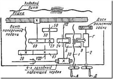
Rice. 241. Kinematic diagram of the apron of the screw-cutting lathe 1A62
The falling worm rotates the worm wheel z = 30, sitting on the shaft VII. A gear wheel z = 24 can be moved along the spline part of this shaft, coupling it either with the wheel z = 50 of shaft VI to obtain mechanical longitudinal feed, or with wheel 2 = 65 of shaft VIII to obtain mechanical transverse feed.
When the gearwheel z = 24 is engaged with the wheel z = 50, the wheel 2 = 23 also rotates. From it, the rotation of the wheel z = 69 and z = 12, sitting on the shaft V. and thus imparts mechanical longitudinal feed to the caliper.
In the longitudinal direction, the caliper can also be moved manually by turning the handwheel sitting on the end of shaft IV. This flywheel, through the wheels z = 15 and z = 69, rotates the shaft V with the rack and pinion wheel z = 12.
If the wheel 2 = 24, sitting on the splined shaft VII, is coupled, with the wheel 2 = 65 on the shaft VIII, the wheel 2 = 20 and the screw IX of the transverse feed will start to rotate, as a result of which the caliper will receive a mechanical transverse feed.
It is possible to carry out the lateral feed of the caliper also manually by turning the handle fixed at the end of screw IX. In this case, the wheels z = 65 and z = 24 are preliminarily disengaged.
To turn on the longitudinal feed when cutting the thread, you need to close the detachable nut on the lead screw I and when it rotates, this nut, together with the apron, will move along the machine axis.
A feature of the apron device in the 1A62 machine is that its four-way worm automatically turns off when the resistance to the movement of the support increases excessively, for example, at the moment of its contact with the longitudinal or transverse stops, due to a sudden overload of the cutter, from random obstacles, etc. This device is called falling worm, because when overloaded, the worm disengages (falls out of the teeth of the worm wheel) and further movement of the caliper stops.
The device of the falling worm is shown in Fig. 242. The worm 2 sits freely on the shaft 9, which is connected to the shaft III by means of the articulated coupling 1 (see Fig. 241). At the end of the worm is the left half 3 of the cam clutch, which engages with its right half 5 beveled end cams. The right half of the coupling can move along the splines of the shaft 9. The spring 7 presses the right half of the coupling to the left half, so that the worm 2 is driven from the rotating shaft 9 and the right half 5 of the coupling.
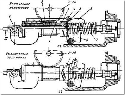
Rice. 242. Falling Worm
When the caliper meets any obstacle in its path, the load on the worm wheel 2 = 30 increases greatly. In accordance with this, the resistance to rotation of the worm will increase 2. When this resistance goes beyond the permissible limits, the right half of the cam clutch 5, which continues to rotate, will begin to rotate relative to the left half 3. At the same time, it moves to the right, compressing the spring 7 (see Fig. 242 , b). Moving to the right, the clutch 5 will move the bracket 8, which, with the help of the bar 6, supports the worm in engagement with the worm wheel 2 = 30 (Fig. 242, a). When the bracket 8 is pushed to the right (Fig. 242, b), the worm, which is no longer supported by the bar 6, falls down under its own weight, disengages from the worm wheel, and the feed stops.
To turn on the worm, use the handle 4, with which the bracket 8 rises with it and the bar 6.
Blocking
To prevent incorrect switching on,
which can lead to damage to the machine, tool or injury to the worker, there are usually locking devices in the mechanisms of screw-cutting lathes. For example, it is impossible to turn on the feed mechanism driven from the drive shaft and at the same time connect half of the split nut on the lead screw, as this can lead to breakdown of the machine; it is also impossible to simultaneously turn on the longitudinal and transverse feed of the support.
The design of the locking devices of screw-cutting lathes is very diverse. In fig. 243 shows a diagram of the mechanical blocking of feeds in the apron of the 1A62 screw-cutting lathe. The locking mechanism is structured as follows. The handle A, fixed on the screw 1 with a large thread pitch, serves to move the nut B with the fork B. This fork, moving the gear wheel z = 24 along the shaft VII (see Fig. 241), engages it either with the wheel z = 50 at turning on the longitudinal feed, or with the wheel z = 65 of the VIII shaft when turning on the transverse feed.
With the middle position of the wheel z = 24, as shown in Fig. 245, neither longitudinal nor transverse feeds are included. In this case, nut B is in a position in which the protrusion of the sleeve G freely passes through the slot of nut B
and thus the shaft 2 can be rotated in any direction. By rotating the shaft 2 using the handle D, the split nut is switched on and off. When the feed from the drive shaft is turned off, you can turn on and off the lock of the detachable nut by turning the handle D shaft 2. When the lock is locked, the protrusion of the sleeve G enters the cutout of the nut B and does not allow
Rice. 243. Locking mechanism of the screw-cutting lathe 1A62
move it in one direction or the other, that is, do not turn on the feed from the drive shaft. At open lock the protrusion of the sleeve G comes out of the cutout of the nut B and allows, by moving it, to turn on the feed from the travel shaft. In this case, the protrusions of the displaced nut B do not allow turning the handle D to the left and closing the lead screw lock.
- 1,931 views
Before proceeding with the adjustment of the lathe, it is necessary to prepare it for work in accordance with the instructions. Before starting work, the turner must make sure that the machine follows all the commands and that the movements of the slide slide (manually and automatically) are carried out smoothly, without jumps, jerks and jams. First, you need to check the reliability of the chuck fastening on the spindle of the machine, then, at idle, check the execution of the machine commands for starting and stopping the electric motor, turning the spindle on and off, turning on and off the mechanical feeds of the support.
After making sure that the machine is in good working order, they start adjusting it.
Let's consider the setup using the example of the most universal machine turning group - screw-cutting lathe with manual control (see Fig. 4.2).
Cutting data setting consists in the kinematic preparation of the machine for processing the workpiece in accordance with the selected or specified cutting mode. For this, the kinematic chains of the machine are adjusted by setting the speed controls of the main movement and feed to the proper positions. Often, the required gear ratios of the tuned chains are pre-calculated, then these ratios are established using the gearbox handles and the feed box, switching the speed of the variable electric motor, installing the appropriate gear wheels, interchangeable cams, copiers, etc.
Setting up the high-speed chain of modern screw-cutting lathes does not require any calculations and consists in switching the gearbox handles to positions corresponding to a given spindle speed. To reduce the switching time, the machines have tables indicating which handle position corresponds to a certain speed value. With stepless regulation, the spindle speed is indicated by a dial gauge.
The feed movement during turning is imparted by the travel roller to the slide carriage or its cross slide. The required feed per revolution of the spindle is set by switching the handles without any calculations. The values of possible feeds to facilitate the switching process are pre-calculated and arranged in the form of tables given in the passport of the machine.
When cutting threads, both tuning organs are used - a feed box and a guitar of replaceable wheels, which is rebuilt only when the type of threads being cut is changed. The replacement wheels required for this are supplied with the machine. Changing the gear blocks in the feed box and changing the guitar gears ensure the machine is set up for cutting most standard threads... The list of standard threads is given in the data sheets of the corresponding models of lathes.
The screw-cutting chain of the screw-cutting lathe is shown schematically in Fig. 9.1. In some models of machines in the feed chain there can also be transmissions with a constant total gear ratio (not shown in the figure).
Rice. 9.1. Screw-cutting chain of a screw-cutting lathe:
1 - lead screw; 2 - feed box; 3 - guitar of replaceable gear wheels; 4 - step increase link; Р х.в - lead screw pitch; P is the pitch of the thread to be cut; D r - direction of cutting motion; D s - the direction of movement of the feed; i k, i u.sh, and i g are the gear ratios of the feed box, the step increase link and the guitar of replaceable gear wheels
The adjusting elements of the screw-cutting chain are calculated and adjusted in such a way that the longitudinal movement of the caliper per one revolution of the spindle exactly corresponds to the step 1 P of the thread to be cut.
The total gear ratio of the specified cutting chain
i "= i" g i "to i" u.sh
where i "g, i" k and i "u.sh - gear ratios, respectively, of a guitar of replaceable gear wheels, a feed box and a step increase link.
To set up the machine, use the following relationship:
The pitch of the thread to be cut P and the pitch of the lead screw with the value of P x.v must be indicated in the same units of measurement.
Installation and fastening of cutting tools on machines produced using a variety of devices (holders, mandrels, cutting blocks), which belong to the auxiliary tool and in most cases are normalized.
The next adjustment element is the selection and installation of the cutter in the tool holder along the height of the machine center axis (Fig. 9.2). To do this, the tool holder is brought to the center of the tailstock, the top of the cutter head is set so that the overhang of the cutter does not exceed 1 ... 1.5 of the height of its holder, the relative position of the top of the cutter head and the center of the machine is determined and they are aligned in height by introducing shims under the tool holder ... The shims should have parallel and well-processed surfaces, should not extend in length and width beyond the support surface of the tool holder. The number of pads should be no more than two.
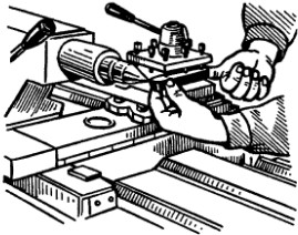
Rice. 9.2. Installation of a cutter in a tool holder along the axis of the centers of the machine
Clamping devices... Depending on how the workpiece is to be positioned and secured on the machine - in the centers, in the chuck, etc. - select devices (see Ch. 4).
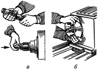
For example, when installing a three-jaw self-centering chuck on the machine spindle (see Fig. 4.11), first wipe the thread or tapered end and tapered bore of the spindle with a cleaning material slightly moistened with kerosene. Then they clean internal thread or the tapered bore of the cartridge adapter flange. A guide mandrel is inserted into the tapered hole of the spindle with a sharp movement (Fig. 9.3, a); take the cartridge with both hands (Fig. 9.3, b) and carefully put it on the guide mandrel. Further, by moving the chuck to the left and rotating it, the first threads of the spindle and chuck are aligned.
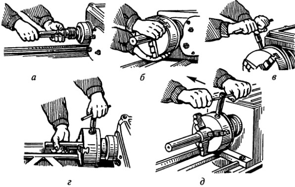
Rice. 9.3. Installation and removal three-jaw chuck:
a - installation of the mandrel; b - installation of a three-jaw chuck on the spindle; c - fixing the cartridge; d - fixing the workpiece; d - cartridge release
Then, supporting the chuck with your left hand from below and simultaneously rotating it right hand, turn the cartridge to failure. With a wrench inserted into one of the square holes of the cartridge, they slightly pull it towards themselves and sharply (with effort) turn it away from themselves to failure (Fig. 9.3, c). In order to avoid self-loosening of the chuck, the teeth of the locking crackers are inserted into the grooves of the spindle and firmly fastened with screws; remove the guide mandrel by pushing it (with a light blow) with a brass bar through the hole in the spindle.
To install the workpiece in a three-jaw self-centering chuck, use the left hand to spread the chuck's jaws with a key (Fig. 9.3, d) so that the workpiece passes between the jaws; with the right hand, the workpiece is inserted between the cams and first clamped with the left hand, and then, rotating the key with both hands, the workpiece is finally fixed in the chuck.
If the processing is carried out in the centers, then to remove the chuck (Fig. 9.3, e), the chuck jaws are first spread apart and the mandrel is fixed in the spindle bore; then they remove the locking crackers and, inserting the key into the socket of the cartridge, sharply turn the cartridge towards themselves, and then, supporting the cartridge with the left hand and intercepting with the right, carefully screw the cartridge onto the mandrel and remove it from the machine.
After removing the mandrel, carefully wipe the spindle taper bore and center taper shank. Then, with the right hand, insert the center (shank) into the hole of the spindle and with a sharp movement insert it to failure (Figure 9.4, a). Turn the spindle on and check the center for radial runout. If the center rotates with a beating, then it is knocked out with a brass bar and reinserted into the spindle hole, turning 30 ... 45 ° around the axis. Then, with your left hand, insert the center into the tailstock quill.
Rice. 9.4. Center installation and driver chuck:
a - insertion with the right hand of the center into the spindle bore to failure; b - installation of the driver cartridge
To check the alignment of the centers tailstock is brought to the left so that the distance between the tops of the centers is no more than 0.5 mm; fix the quill and check (by eye) the coincidence of the vertices in the horizontal plane. If the vertices of the centers do not coincide, then they achieve their coaxiality by displacing the tailstock. After that, the driver chuck is installed (Fig. 9.4, b) using the same techniques as when installing the three-jaw chuck.
Control questions
- How are cutting conditions set up on a screw-cutting lathe?
- How do you set up a cutting tool during turning?
- Tell us about the techniques for setting up a three-jaw chuck.
1 When cutting multi-start threads, the chain is adjusted to the thread lead, which is equal to the product of the thread lead by the number of its starts.
Hello again! Today the topic of my post is the main movements in turning such as cutting speed and feed. These two components of cutting conditions are fundamental for turning metal and other materials.

The main movement or cutting speed.
If we look at the figure above, we will see that it is the workpiece that makes the main movement during the machine. It can rotate both clockwise and counterclockwise. Basically, as we see, the rotation is directed towards the cutter, since this ensures the shearing of the surface layer from the workpiece and the formation of chips.
The rotation of the workpiece is given by the spindle of the lathe and the range of spindle revolutions (n) is large enough and can be adjusted depending on the diameter of the part, its material and the used cutting tool. When turning, it is mainly
The cutting speed for turning is calculated by the formula:
V- this is the main movement called cutting speed.
P Is a constant constant which equals 3.14
D- diameter of the workpiece (workpiece).
n- the number of revolutions of the machine spindle and the part clamped in it.
Feed motion for turning.
You probably already understood about the feed movement. YES is the movement of the cutting tool that is clamped in the tool holder (for this sketch). The attachment of the incisors may be different, but more on that later 🙂. To apply for lathe a special kinematic scheme of gears is used. If this is simple turning, then the synchronization of the rotation of the workpiece and the cutting tool is not important, but if you decide to cut the thread, then everything will be different. We will talk about this in the following articles. If you don't want to miss them then subscribe to my blog updates.
The formulas for calculating the feed motion on a lathe look different, because it can be either feed per revolution or minute feed.
Feed per revolution- this is the distance that the cutting tool travels in our case, the cutter in one revolution of the workpiece. The definition may differ depending on the type of processing. For example, when is the distance the workpiece moves relative to the cutter in one revolution.
Minute feed- This is the distance that the cutter travels in one minute (which is logical from the name).
Cutting speed and feed. Conclusion.
And so you can summarize. Today we have learned about the main movements in turning such as cutting speed and feed. I do not aim to load you with a mass of formulas and heavy-duty definitions of them you can find in various books about mechanical engineering and metal cutting, I want to explain the basic concepts to you in human and understandable language. I think we will succeed 🙂.
That's all for today. See you soon friends!


 Future marriage of Prince Harry year NTV")


Energy drinks: give vigor, but take away health What will happen if you drink 4 energy drinks
Mustard for weight loss: how to use the seasoning with maximum benefit Is it possible for children to have mustard
The benefits and harms of mustard for the human body Table mustard benefits and harms
How to treat the ear after piercing: types of antiseptics, their composition, rules and features of the treatment of a pierced ear
Sistine Chapel in the Vatican: description, history, architectural features