Numerical systems program control
Basic principles of numerical control
The development of electronics and computer technology, the introduction of computers into production has led to the development and widespread use in machine tool building of numerical control systems (CNC) for metal-cutting machines, as well as other technological equipment.
Numerical control of metal-cutting machines is called control according to a program specified in an alphanumeric code and representing a sequence of commands written in a certain language and providing the specified functioning of the working bodies of the machine.
The fundamental difference between CNC systems and the previously considered ACS is the method of calculating and setting the control program and its transmission to control the working bodies of the machine. Detail drawing information is presented in analog-digital form, that is, in the form of numbers, various verbal instructions, conventional signs and other symbols that have a limited number of meanings, each of which has quite specific and unambiguous information.
In conventional ACS, the control program is embodied in physical analogues - cams, copiers, stops, jig plates and other means that are program carriers. This method task control program has two basic drawbacks.
First is caused by the fact that the information of the drawing of the part from digital (discrete) and unambiguous turns into analog (in the form of cam curves, copier). This leads to errors introduced in the manufacture of cams, copiers, the arrangement of travel stops on the rulers, as well as the wear of these software carriers during operation. Second The disadvantage is the extreme importance of manufacturing these software carriers with subsequent labor-intensive setup on the machine. It leads to high costs means and time and makes in most cases inefficient the use of conventional ACS for the automation of serial and especially small-scale production.
When preparing control programs for CNC machines up to its transfer to the working bodies of the machine, we are dealing with information in a discrete form, obtained directly from the drawing of the part.
The trajectory of the movement of the cutting tool relative to the machined workpiece in CNC machines is represented as a series of its successive positions, each of which is determined by a number. In CNC machines, it is possible to obtain complex movements of the working bodies not with the help of kinematic connections, but by controlling the independent coordinate movements of these working bodies according to a program specified in numerical form. Qualitatively new in CNC machines is the possibility of increasing the number of simultaneously controlled coordinates, which made it possible to create fundamentally new layouts of machine tools with obtaining wide technological capabilities with automatic control.
The control program must be calculated with any given accuracy and for any required law of movement of the working bodies of the machine. The control of machine tools directly from the computer is gaining more and more widespread use.
Classification of CNC systems
CNC systems can be classified according to various criteria.
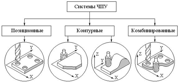
I. Based on the technological tasks of processing control All CNC systems are divided into three groups: positional, contour and combined.
Positional CNC systems provide control of movements of the working bodies of the machine in accordance with the commands that determine the positions specified by the control program. In this case, movements along different coordinate axes can be performed simultaneously (for a given constant speed) or sequentially. These systems are mainly used for drilling and boring machines for processing parts such as plates, flanges, covers, etc., in which drilling, countersinking, boring holes, threading, etc.
CNC contouring systems provide control of the movements of the working bodies of the machine along the trajectory and with the contour speed specified by the control program. The contour speed is the resulting feed rate of the working body of the machine, the direction of which coincides with the direction of the tangent at each point of the specified processing contour. Contour CNC systems, unlike positional ones, provide continuous control of tool or workpiece movements one by one or simultaneously along several coordinates, which makes it possible to process very complex parts (with control over more than two coordinates simultaneously). CNC contouring systems are mainly equipped with turning and milling machines.
Combined CNC systems, combining the functions of positional and contour CNC systems, are the most complex, but also more versatile. In connection with the complication of CNC machines (especially multi-operational ones), the expansion of their technological capabilities and the increase in the degree of automation, the use of combined CNC systems is expanding significantly.
II. Availability feedback All CNC systems are divided into two groups: open and closed.
Closed CNC systems, in turn, are:
1) with feedback on the position of the working bodies of the machine; 2) with feedback on the position of the working bodies and with compensation for machine errors; 3) self-adapting (adaptive).
open CNC systems are built on the basis of power or stepper motors (SM). In the latter case, the stepper motor is usually used in conjunction with a hydraulic booster.
III. Classification based on the level of electronic technology.
Despite the relatively short period of use of CNC systems, they have already gone through several stages in their development, determined by the level of development of electronic technology.
CNC systems currently used in industry class NC built on the basis of a digital model. In this system, the program (on punched tape) is entered into interpolator 3, further revised
the program is entered into the control system 2 machine 1. These CNC systems are called systems with a rigid program. The possibilities of operator intervention in the process of program processing are very limited on these systems.
In systems class SNC the device for reading the control program is used only once - to enter the control program into

storage unit 4 (memory). As a result, the reliability of the machine is increased due to the failure of the photoreader.
Feature of control systems CNC class is their structure corresponding to the structure of the control computer. With the advent of CNC class systems, the functionality of program control has expanded,
including storage of the control program and its editing directly at the workplace, advanced display options, dialog communication with the operator, etc. The input of the control program must be carried out on punched tape or manually. The second type of systems is called systems class HNC. The control program here is entered by the operator using the keyboard and stored in the system memory.
As well as autonomous systems CNC in industry use direct numerical control systems for a group of different machine tools from a single computer, called systems DNC class.
 In this system, a medium or large computer (3) prepares programs for several CNC machines and transfers them to the CNC systems (2) of individual machines (1). Due to the very high speed of the computer, the system prepares programs for all machine tools of the group. The computer also performs additional functions for managing a semiautomatic device, for example, it controls automated transport and a warehouse. Machine tools are directly controlled by minicomputers with a small volume random access memory included in individual CNC systems.
Typical block diagram of a CNC system
The figure shows a general enlarged block diagram of the CNC system. It includes the following main elements: CNC device; feed drives of the working bodies of the machine and feedback sensors (DOS) installed for each controlled coordinate. The CNC device is designed to issue control actions by the working body of the machine in accordance with the control program entered on the punched tape. The control program is read sequentially within one frame with storage in the memory block, from where it is fed into the blocks of technological commands, interpolation and feed rates. The interpolation block is a specialized computing device (interpolator) that formulates a partial trajectory of the tool movement between two or more points specified in the control program. The output information from this block enters the feed drive control unit, usually presented as a sequence of pulses for each coordinate, the frequency of which determines the feed rate, and the number determines the amount of movement.
Information input and reading block is intended for input and reading from the punched tape of the control program. Reading is carried out sequentially line by line within one frame with periodic pulling of a punched tape in front of a photo reader containing a photo reading head 11 with photo converters, and an illuminator,
consisting of an incandescent lamp 3 and a lens 4. Eight photoconverters provide information reading, and two are used to generate a sync pulse through the holes of the transport track. In other devices, another photoconverter is used, which is installed along the edge of the punched tape to control its breakage.
Pulling punched tape 9 is carried out by drive roller 7, to which it is pressed by roller 10, when the broach electromagnet (EMF) is turned on and armature 6 is pulled. braked by brake 1 and pressed against head 11 by clamp 5, which is retracted by lever 2 when punched tape is loaded. After reading the information of one frame, the punched tape is stopped by turning on the EMT brake and turning off the EMF electromagnet. Synchronization of their work is carried out by a control trigger (TG).
There are modifications to the input device.
Memory block. Since the information from the punched tape is read sequentially, and is used all at once within one frame, when reading it, it is stored in the memory block. Here, it is also monitored and a signal is generated when an error is detected in the punched tape. Since the processing of information proceeds sequentially by frames, and the time for reading information from one frame is approximately 0.1 - 0.2 s, a gap in the transmission of information is obtained, which is unacceptable. For this reason, two blocks of memory are used. While the information of one frame from the first memory block is being processed, the second frame is read from the punched tape and stored in the second block. The time for introducing information from the memory block into the interpolation block is negligible. In many CNC systems, the memory block can receive information bypassing the input block and reading directly from the computer.
interpolation block. This specialized computing device, ĸᴏᴛᴏᴩᴏᴇ forms a partial tool path between two or more points specified in the control program. This is the most important block in CNC contouring systems. The basis of the block is the interpolator, which, according to the numerical parameters of the contour section specified by the control program, restores the function f (x, y). In the intervals of X and Y coordinate values, the interpolator calculates the coordinate values of the intermediate points of this function.
At the outputs of the interpolator, control pulses strictly synchronized in time are generated to move the working body of the machine along the corresponding coordinate axes.
Apply linear and linear - circular interpolators. In accordance with this, the former produce linear interpolation, and the latter linear and circular.
A linear interpolator provides, for example, the movement of a working body with a cutter with a diameter between two reference points in a straight line with a deviation from a given contour by a value.
In this case, the initial information for the interpolator is the magnitude of the increments in coordinates and the processing time of moving along a straight line, ᴛ.ᴇ. , where S is the set tool feed rate.
The operation of a linear-circular interpolator can be carried out according to the method of the evaluation function F. The method essentially consists in the fact that when the next control pulse is generated, the logic circuit evaluates on which coordinate this pulse should be issued so that the total movement of the working body of the machine tool as close as possible to it to a given contour.
The interpolated line (see Fig. a) divides the plane in which it is located into two regions: above the line, where the evaluation function F>0, and below the line, where F<0. Все точки, лежащие теоретически заданной линии, имеют F=0.
The interpolation trajectory is a certain sequence of elementary movements along the coordinate axes from the starting point with coordinates to the end point with coordinates , .
If the intermediate point of the trajectory is in the region F>0, then the next step is taken along the X axis. If the intermediate point is in the region F<0, шаг делается по оси Y. Аналогично происходит работа интерполятора при круговой интерполяции (см. рис. б).
Feed drive control unit. From the interpolation block, the information is fed to the feed drive control unit, which converts it into a form suitable for controlling feed drives. The latter is done so that upon receipt of each pulse, the working body of the machine moves by a certain amount, characterizing the discreteness of the CNC system. With the arrival of each pulse, the controlled object moves by a certain amount, called the price of the pulse, which is usually 0.01 - 0.02 mm. Given the dependence on the type of drive (closed or open, phase or amplitude) used on machines, control units differ significantly. In closed-loop phase-type drives using feedback sensors in the form of rotating transformers operating in the phase shifter mode, control units are pulse-to-phase AC converters and phase discriminators that compare the phase of the signal at the output of the phase converter with the phase of the feedback sensor and output a differential error signal to the drive power amplifier.
Feed rate block- provides a given feed rate along the contour, as well as acceleration and deceleration processes at the beginning and at the end of processing sections according to a given law, most often linear, sometimes exponential. In addition to working feeds (0.5 - 3000 mm / min), this block provides, as a rule, idling with an increased speed (5000 - 20000 mm / min).
Control and indication panel. The operator communicates with the CNC system through the control and display panel. With the help of this console, the CNC system is started and stopped, the operating mode is switched from automatic to manual, etc., as well as the correction of the feed rate and tool sizes and changes in the initial position of the tool in all or some coordinates. This console contains a light signaling and digital indication.
Program correction block used to change the programmed machining parameters: feed rate and tool dimensions (length and diameter).
Block of canned cycles serves to simplify the programming process when processing repeating elements of a part (for example, drilling and boring holes, threading, etc.) a block of canned cycles is used. For example, such movements as fast withdrawal from a finished hole are not programmed on a punched tape - ϶ᴛᴏ is incorporated in the corresponding cycle (G81).
Block of technological commands provides control of the cycle of the machine (its cyclic automation), including the search and analysis of the cutting tool, switching the spindle speed, clamping and unclamping the moving working bodies of the machine, various interlocks.
Power Supply supplies the necessary constant voltages and currents to all CNC units from a conventional three-phase network. A feature of this block is the presence of voltage stabilizers and filters that protect the CNC electronic circuits from interference that always occurs in industrial power networks.
Feedback sensors (DOS)
DOS are designed to convert the linear movements of the working body of the machine into electrical signals containing information about the direction and magnitude of movements.
The whole variety of DOS can be conditionally divided into angular (circular) and linear. Circular DOS usually convert the angle of rotation of the lead screw or the movement of the working body of the machine through a rack and pinion gear. The advantage of circular DOS is their independence from the length of movement of the working body of the machine, ease of installation on the machine and ease of operation. The disadvantages include the principle of indirect measurement of the displacement of the working body, and therefore the measurement error.
Linear DOS directly measure the movement of the working body, which is their main advantage compared to circular DOS. The disadvantage of linear DOS is the dependence of their overall dimensions on the amount of movement of the working body, in addition, they are difficult to install and operate the machine.
According to the principle of operation, DOS are pulsed, phase, code, phase-pulse, etc. The most commonly used sensors are inductosin type, which are circular and linear, as well as resolvers.
The linear inductosyn consists of a ruler 1 and a slider 2. The length of the ruler slightly exceeds the value of the measured displacement, the ruler has one printed winding with a pitch of 2 mm, from which the induced voltage is removed. It must be solid (with a short stroke) or assembled from several plates (250 mm long). The slider is installed on the working body and moves relative to the ruler. It has two printed windings shifted by ¼ pitch. An alternating current with a frequency of 10 kHz is supplied to each winding, and the voltage on the first winding ![]() , and on the second
, and on the second ![]() , where is the specified offset angle.
, where is the specified offset angle.
When the slider 2 moves, a voltage is induced at the output of the winding of the ruler 1
where is the actual displacement angle, reflecting the actual movement of the working body, ᴛ.ᴇ.
If the working body is in a predetermined position, the voltage at the output of the line winding is zero. In the absence of this equality, the feed drive receives a signal for further movement.
DOS of the rotating transformer type (VT) are widely used in CNC machines. 
Οʜᴎ are two-phase AC electrical machines, in which, when the rotor rotates, the mutual induction between the windings of the stator 2 and rotor 1 changes sinusoidally with high accuracy. Voltage is applied to the winding (a) of the stator, and to the winding (b) - , where is the displacement angle, reflecting the given amount of displacement. Voltage is removed from the rotor winding 1. The number of windings in the VT should be different, but most often VT is used with two mutually perpendicular windings on the stator and on the rotor. Such sine-cosine VTs are called resolvers.
In positional CNC systems, code feedback sensors are used to measure the absolute value of the displacement of the working body. As such a sensor, for example, a code disk of a circular photoelectric sensor with ten binary digits is used.
Each concentric ring of the glass disk consists of dark and transparent areas that do not transmit or transmit light to photodetectors. Rings correspond to certain digits: external - to the first, internal - to the tenth. The disk is installed so that its full revolution corresponds to the movement of the working body to the maximum value. In this case, each position of the working body corresponds to a single combination (code).
The figure shows a diagram of a pulsed linear sensor with a fixed diffraction grating 1, relative to which the movable auxiliary scale 2 moves. It is rotated relative to the main grating by an angle, in connection with this, when it moves by an amount, moiré fringes moving in the vertical direction are formed (3) , which periodically block the beam of light (4) passed through the grating to two photocells. When moving the auxiliary scale 2 by 1 step of strokes, one pulse comes from the photocells.
General principles of program coding
In CNC machines, all elements of the program: direction, magnitude and speed of given working and auxiliary movements, etc. are set in digital form - in the form of numbers arranged in a certain order and written in a certain way using some code. The code is a conditional record of a number or action, which allows, in a fairly simple way, to obtain an image of this number in a form convenient for use in PU systems. In the general case, any code used in program control systems consists of two basic elements: a movement code and an auxiliary instruction code. There are many different ways to encode.
Unitary code. The essence of this code is essentially that in it any number is expressed by one sign 1. To represent any number, you need to repeat this sign as many times as many times as the given number contains units. When used as a program carrier - punched tape, sign 1 is expressed by punching a hole, and with a magnetic tape - a magnetic stroke. The main drawback is the low recording density.
Decimal number system uses ten digits 0 - 9 to write numbers. To write numbers in the decimal number system, each character must have its own track, and each digit - a line. Writing numbers in decimal code is cumbersome.
Binary number system uses only two characters 0 and 1 for writing. To write a number in binary code, one corresponds to the presence of a signal, and at zero, there is no signal. This is convenient because the mechanisms most reliably distinguish between two stable states. For example, on punched tape: there is a punch, there is no punch. ; ; ; (2+1); ; (4+1); (4+2); (4+2+1); ; (8+1); (8+2) etc.
Binary-decimal number system.
In this case, each digit of the decimal number is written with a binary equivalent, called a tetrad:
0 1 2 3 4 … 10 11
0000 0001 0010 0011 0100 … 0001,0000 0001,0001
International ISO code - 7bit
Despite the large number of types of processing and types of machines, a relatively limited set of commands encoded by certain characters or numbers is sufficient to communicate extremely important information.
To ensure the use of codes used in CNC machines, the unification of programming languages has been carried out on a large scale. To this end, the international organization of ISO standards has adopted a single international code for programming processing on CNC machines. In our country, there is a similar code (GOST 13052 - 74). The code establishes a set of specific characters, which are divided into numeric, alphabetic in uppercase letters of the Latin alphabet, and graphic. Each character has a unique expression, obtained by punching holes on a paper eight-track tape. 25.4 mm wide. The first track from the left (eighth) is for the parity and odd parity check feature. It is necessary that in each line of punched tape the number of punched holes be an even number. The remaining seven tracks represent the corresponding bit in the binary number system.
Each direction of movement of the working bodies of the machine tools is assigned the value of a certain coordinate and the corresponding address symbol, for example: X, Y, Z, W, etc. There is a single direction of the axes of the coordinate axes of metal-cutting machines. The positive direction of movement of the machine element is considered to be the one in which the machining tool (its holder) and the workpiece recede from each other.
Numerical control systems - concept and types. Classification and features of the category "Numerical control systems" 2014, 2015.
Lecture plan:
1. Numerical control of equipment and
his role in production.
2. The main advantages of using CNC machines.
3. The structure of the complex "Machine with CNC".
4. The concept of the CNC system and its main functions.
5. Positional, contour and combined CNC systems.
1. Numerical control of equipment and its role in production
The most important reserve for the growth of labor productivity in mechanical engineering is the reduction in the labor intensity of machining parts on metal-cutting machines. The main way to use this reserve is to automate the processes of machining parts based on the use of machine tools with numerical control (CNC), as well as automatic lines and automated sections based on these machines.
Automation of large-scale and mass production is ensured by the use of automatic machines and automatic lines. For small-scale and serial production, covering approximately 75-80% of engineering products, automation tools are needed that combine the productivity and accuracy of automatic machine tools with the flexibility of universal equipment.
Such means of automation are CNC machines. The CNC machine is a machine with a flexible connection, the operation of which is controlled by a special electronic device. The part processing program is written in numerical form on the program carrier and implemented using the CNC system. In this case, the accuracy of setting dimensions does not depend on the properties of the program carrier, but only on the resolution of the CNC system. The CNC machine does not require a long readjustment when switching to the processing of a new part. To do this, it is enough to change the program, cutting tool and fixture. This allows you to process a wide range of parts on the machine. Working in an automatic cycle, the CNC machine retains the properties of a universal machine with manual control.
The use of CNC machines places new demands on the design and processing of parts. The technological preparation of production (TPP) is changing radically: its center of gravity is transferred from the sphere of production to the sphere of engineering labor, it becomes more complex and increases in volume.
New elements of the technological process appear: tool path, path correction, processing control program, dimensional alignment of the position of the part and tool in the sledge coordinate system, tool setting outside the machine with high accuracy, etc.
The nature and volume of work of the technologist is radically changing. CNC machining makes it possible to formalize this process and apply computers and other means of automation of engineering work to the design of technological processes.
The introduction of CNC machining into production is a major organizational and technical event. It must be accompanied by a carefully thought-out plan of all the work arising from this task, including such a priority one as training the necessary staff and training specialists in the field of designing technological processes for machining on CNC machines.
Engineer-mechanic specialty 12.01.00 "Technology of mechanical engineering" must be able to solve issues on which the successful use of CNC machines in mechanical engineering depends. To do this, he must have a good knowledge of the technological capabilities of CNC machines and their technical equipment, a feasibility study for the feasibility of using CNC machines, methods for designing technological processes for processing parts on these machines, methods for developing control programs (NC), the procedure for compiling and processing technological documentation .
MACHINE AUTOMATIC CONTROL SYSTEMS
The automatic control system is a complex of devices and means of communication that ensures accurate and time-coordinated interaction between the working and auxiliary actuators of the machine in accordance with the control program developed on the basis of the accepted technological processing. Control program - ϶ᴛᴏ a sequence of commands that ensure the specified functioning of the working parts of the machine. . An element or a complex of elements that carry a control program is commonly called a program carrier
The classification of automatic control systems and their comparative analysis is given in the manual for independent work of students. Control systems with RV (with a camshaft), cyclic program control and tracking copying systems are also considered there.
The development of electronics and computer technology, the introduction of computers into production has led to the development and widespread use in machine tool building of numerical control systems (CNC) for metal-cutting machines, as well as other technological equipment.
Numerical control is called control according to a program specified in an alphanumeric code and representing a sequence of commands written in a certain language and providing the specified functioning of the working bodies of the machine.
The fundamental difference between CNC systems and previously developed ACS lies in the method of calculating and setting the control program and its transmission to control the working bodies of the machine.
In conventional ACS, the control program is embodied in physical analogues - cams, copiers, stops and other means that are program carriers. This method of specifying the control program has two basic drawbacks. The first one is caused by the fact that the detail drawing information is converted from digital (discrete) into analog (in the form of cam curves, copier). This leads to errors introduced in the manufacture of cams, copiers, the arrangement of travel stops on the rulers, as well as the wear of these software carriers during operation. The second disadvantage is the extreme importance of manufacturing these software carriers with subsequent labor-intensive setup on the machine. This leads to large expenditures of money and time, and in most cases makes it inefficient to use conventional ACS for the automation of serial and especially small-scale production.
In CNC systems, all the way through the preparation of a control program up to its transfer to the working bodies of the machine, we deal only with information in digital (discrete) form, obtained directly from the drawing of the part. The trajectory of the movement of the cutting tool relative to the workpiece in CNC machines is represented as a series of its successive positions, each of which is determined by a number. All information of the control program (dimensional, technological and auxiliary) necessary to control the processing of the part, presented in text or tabular form using symbols (numbers, letters, symbols), is encoded (ISO-7bit code) and entered into the memory of the control system from computer or directly using the keys on the control panel. The CNC device converts this information into control commands for the actuators of the machine and controls their execution.
For this reason, in CNC machines, it became possible to obtain complex movements of its working bodies not due to kinematic connections, but due to the control of independent coordinate movements of these working bodies according to a program specified in numerical form. Qualitatively new in CNC machines is the possibility of increasing the number of simultaneously controlled coordinates, as a result of which it became possible to apply fundamentally new layouts of machine tools with obtaining wide technological capabilities in automatic control.
The general enlarged block diagram of the CNC system is shown in fig. twenty.
It includes the following main elements: CNC device; feed drives of the working bodies of the machine and feedback sensors (DOS) installed for each controlled coordinate. The CNC device is designed to issue control actions to the working bodies of the machine in accordance with the control program entered into the block for input and reading information. The control program is read sequentially within one frame with storage in the memory block, from where it is fed into the blocks of technological commands, interpolation and feed rates.
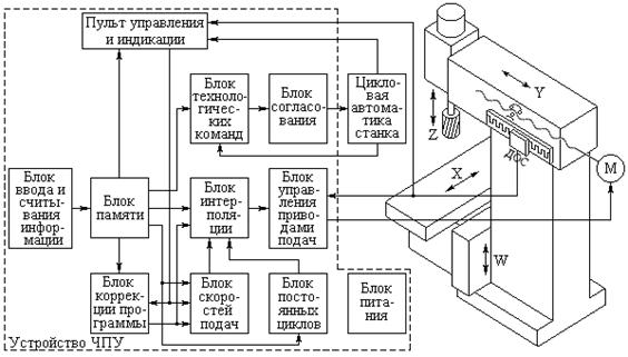 |
Rice. 20 Enlarged block diagram of the CNC system
Block of technological commands serves to control the cyclic automation of the machine, consisting mainly of actuating elements such as starters, electromagnetic clutches, solenoids, limit and travel switches, pressure switches, etc., providing the execution of various technological commands (tool change, switching spindle speeds, etc.), as well as various locks during machine operation.
Interpolation block- a specialized computing device (interpolator) - forms a partial trajectory of the tool between two or more points specified in the control program. The output information from this block, supplied to the feed drive control unit, is usually presented as a sequence of pulses for each coordinate, the frequency of which determines the feed rate, and the number determines the amount of movement. The specified feed rate along the workpiece contour, as well as the processes of acceleration and deceleration, are provided by the feed rate block. The program correction block is used to change the programmed processing parameters: feed rate and tool dimensions (length and diameter). The correction is entered from the control and display panel, which serves to connect the operator with the CNC system. The block of canned cycles allows you to simplify the programming process when processing repeating elements of a part, for example, when drilling and boring holes, threading, etc.
The feed drive of the working bodies consists of a drive motor, its control systems and kinematic links. The accuracy of movement of the working bodies of the CNC machine depends on the applied feed drive control scheme: open (without a system for measuring the actual displacements of the controlled working body) or closed (with a measurement system). In the second case, control of the accuracy of processing control signals for each controlled coordinate of the machine is carried out by a feedback sensor (DOS). The accuracy of this control is largely determined by the type, design and location of the sensors on the machine.
Classification of CNC systems
CNC systems can be classified according to various criteria.
1. Based on the technological tasks of processing control, all CNC systems are divided into three groups: positional, contour and combined.
Positional CNC systems provide control of movements of the working bodies of the machine in accordance with the commands that determine the positions specified by the control program. In this case, movements along different coordinate axes can be performed simultaneously (at a given constant speed) or sequentially. These systems are mainly equipped with drilling and boring machines for processing parts such as plates, flanges, covers, etc., in which drilling, countersinking, boring holes, threading, etc. ).
CNC contouring systems provide control of the movements of the working bodies of the machine along the trajectory and with the contour speed specified by the control program. The contour speed is the resulting feed rate of the working body of the machine, the direction of which coincides with the direction of the tangent at each point of the specified processing contour. Contour CNC systems, unlike positional systems, provide continuous control of tool or workpiece movements one by one or along several coordinates at once (Fig.), As a result, very complex parts can be processed (with control over more than two coordinates simultaneously). CNC contour systems are mainly equipped with turning and milling machines (for example, mod. 16K20F3, 6R13F3).
 |
processing control tasks
Combined CNC systems, combining the functions of positional and contour CNC systems, are the most complex, but also more versatile. Due to the increasing complexity of CNC machine tools (especially multi-operational), expanding their technological capabilities and increasing the degree of automation, the use of combined CNC systems is expanding significantly (for example, mod. IR500MF4, IR320PMF4; 2206PMF4, 6305F4).
2. By the presence of feedback, all CNC systems are divided into two groups: open and closed.
Open-loop CNC systems are built on the basis of power or non-power stepper motors (SM). In the latter case, SD is usually used in conjunction with a hydraulic booster (GU). Although these systems are the simplest, in them, due to the lack of control over the actual position of the working body of the machine, the accuracy of movement will be affected by the errors of the stepper motor, hydraulic booster and transmission mechanisms of the feed drive (gear, screw-nut pairs, etc.).
The operation diagram of a stepper motor with a hydraulic booster is shown in fig. . When the SM rotor is rotated at a certain angle, the screw part 1 of the distributor is unscrewed from the currently stationary nut 2, moving the distributor, for example, to the left. In this case, the oil enters the cavity of the hydraulic motor 3, which through the gear 4 rotates the lead screw 5 of the drive of the working body 6. When the rotor of the hydraulic motor turns, the nut 2 turns (with the screw part of the distributor stationary) and returns the distributor back to its original position until the gap in it is blocked Hey. The latter will occur when the hydraulic motor rotor rotates exactly the same angle that the distributor from the stepper motor turned.
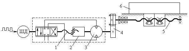 |
Rice. 22. Open-loop feed drive control circuit of a CNC machine
Open-loop CNC systems are equipped with a significant part of CNC machine tools (for example, mod. 16K20F3, 6R13F3, 6R11F3, RT-725F3, 1B732F3).
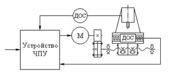
At the heart of the work closed systems CNC is based on the principle of servo control systems. As a drive motor M in these systems, DC motors are most often used.
Closed-loop CNC systems there are: 1) with feedback on the position of the working bodies of the machine; 2) with feedback on the position of the working bodies of the machine and with compensation for machine errors; 3) self-adapting (adaptive).
Closed-loop CNC systems of the first subgroup are of three types. In closed CNC systems of the first type (Fig. 23, a), an indirect measurement of the position of the working body is made using a circular DOS mounted on the lead screw. This scheme is quite simple and convenient in terms of installing DOS. The overall dimensions of the applied sensor do not depend on the magnitude of the measured displacement. When using circular DOS mounted on the lead screw, high requirements are placed on the accuracy characteristics of the screw-nut transmission (manufacturing accuracy, rigidity, absence of gaps), which in this case is not covered by feedback.
The use of precision-made ball screw pairs in feed drives of CNC machines and the creation of a preload in them to eliminate gaps and increase rigidity make it possible to widely use closed-loop CNC systems of the first type to obtain high accuracy of movement of working bodies.
 |
Rice. 23. Structural diagrams of closed CNC systems:
a - closed with a circular DOS on the lead screw;
b - closed with circular DOS and rack and pinion;
c - closed with linear DOS
Closed CNC systems of the third type are equipped with linear DOS (Fig. 23, c), which provide direct measurement of the movement of the working body of the machine. This allows you to cover all the transmission mechanisms of the feed drive with feedback, which ensures high accuracy of movements. At the same time, linear DOS are more complicated and more expensive than circular ones; their overall dimensions depend on the stroke length of the working body of the machine. The accuracy of linear DOS can be affected by machine errors (for example, wear of guides, thermal deformations, etc.).
In all three types of closed CNC systems considered, only the errors of the feed drive of the working bodies of the machine are taken into account and do not take into account the errors of both the machine itself (deviation from the straightness of the guides and their wear, vibrations, thermal deformations of the base parts), and other elements of the technological system (elastic deformations, tool wear, etc.) that affect the accuracy of machining parts.
Closed-loop CNC systems of the second subgroup (Fig. 24) are equipped with additional feedback systems to improve processing accuracy, with sensors D that compensate for machine errors (thermal deformations, vibrations, wear of guides, etc.).
 |
Closed CNC systems of the third subgroup are called self-adaptive (adaptive) control systems. Due to the presence of feedback not only on the position of the working bodies, but also on the parameters of the processing process (elastic deformations of the technological system, tool wear, temperature in the cutting zone, vibration), they provide automatic adaptation of the processing mode of the machine to changing processing conditions (fluctuation of the allowance on the workpiece , its hardness, etc.) to obtain a given machining accuracy, maximum possible productivity or minimum cost of machining.
Despite the relatively short period of use of CNC systems, they have already gone through several stages in their development, determined by the level of development of electronic technology. At the same time, the developers of CNC systems used various element bases: relay-contactor, transistor, microcircuits of a small and medium degree of integration, mini-computers and, finally, microprocessor sets and large memory integrated circuits (LSI memory).
 |
Full text search:
Home > Abstract >Informatics
Introduction 4
Chapter I. The essence of building hardware-software complexes with numerical control 7
§1.1. Equipment with numerical control. Purposes, functions, existing solutions and models 7
§1.2. Stepper motor. Device, principle of operation, control 8
§1.3. Architecture of microcontrollers. Required parameters 12
§1.4. Software environment for the microcontroller 14
§1.5. Software environment for the CNC machine control module at the PC level 15
Chapter II. Implementation of the necessary control modules for the CNC machine 21
§2.1. Physical model of hardware 21
§2.2. Data analysis and structure of the drilling file with *.drl extension. 22
§2.3. Algorithm for reading data in the microcontroller coming from a PC via UART 26
§2.4. Formation of a drilling file for sending to the microcontroller 28
§2.5. Drilling operation 28
§2.6. Manual mode 31
§2.7. Burnout 32
§2.8. Modernization of the CNC complex 38
Chapter III. Analysis and testing of the complex 42
§3.1. Testing the CNC complex in computer simulation complexes 42
§3.2. Drilling module test 43
§3.3. Manual control 45
§3.4. Burnout 46
Conclusion 49
Used literature 51
Introduction
In the modern world, it is no longer possible to do without the use of the latest technologies in almost all areas. Basically, this is the introduction of automation systems into our lives, which make it possible to facilitate human work and increase both the scientific and technological level of knowledge. With the advent of computers, the introduction of such systems has become the most popular and relevant. This is due to the high demand for automatic control systems, both in production and in everyday life.
And in practice, software control of a particular device has received great application. Stepper motors are widely used in printers, automatic tools, disk drives, automotive dashboards and other applications requiring high positioning accuracy and microprocessor control. As is known, such control requires the use of special logic and high-precision drivers that can be implemented on a discrete element base, which increases the complexity of the circuit and its cost.
Machine tools with numerical control (CNC) deserve special attention. Their role today is great, because they can facilitate the work of a person due to their high accuracy, reliability and practicality.
Researchers, developers and system engineers need greater openness of control systems. This openness will make it much easier to design, build, and rapidly deploy functionality to meet the ever-increasing practical needs of programmable controller applications. While some of the robot control vendors provide customized development tools for their products, low-cost and non-proprietary solutions are preferred in terms of being able to quickly respond to market changes and reduce their life cycle cost. The most important success factors are the use of a common element base and open source software (if possible, freely distributed). In turn, software design should be focused on maximum portability and reconfigurability.
The purpose of this thesis is to create a software and hardware complex with CNC control that meets all the above requirements. The CNC complex allows you to perform many tasks that can be set depending on the imagination of the owner. The ultimate goal of this work is to create such control modules and hardware parts that will perform the following:
Hole drilling for PCB manufacturing, automatically controlled by PC;
Manual control of the CNC complex by means of a computer;
Transferring images from a PC to the processed material by heat treatment.
To implement such a software and hardware complex, it is necessary to solve the following tasks:
a) study mechanical technologies to create a working physical area of the machine;
b) understand the principle of management stepper motors;
c) study the architecture and operation of Atmel series microcontrollers;
d) study the mode of data exchange through the RS232 interface;
e) to develop the physical hardware of the complex with a minimum amount of necessary materials and assemblies;
f) to develop a control board for the physical part of the complex and interaction with a PC, directly through the RS232 interface, based on the Atmel microcontroller;
g) develop a program for the microcontroller that ensures the correct operation of the complex;
h) create a software part of the complex on a PC that provides the following operations:
drilling;
Burnout;
Manual control;
i) get acquainted with the latest computer simulators of electronic devices for testing the hardware and software complex.
Chapter I. Essence of building software and hardware complexes with numerical control
§1.1. Equipment with numerical control. Purposes, functions, existing solutions and models
For an introduction to the course of things, let's define the basic terms and meanings.
Computer numerical control or CNC- means a computerized control system that reads instructions into G-code(technical data format for CNC systems, described below) and for controlling machine tools and drives for metalworking machines. The CNC interpolates the movement of the machining tool according to the control program.
This is one of the many definitions of numerical control, taken from wikipedia, hereinafter CNC.
That is, the main distinctive functionality of the CNC is a computerized control system, which implies the presence of controlled equipment and a control terminal. In our case, the controlled equipment will be a multifunctional machine based on CNC control and a control terminal - a computer with a special software package.
To solve the problem, methods with their control algorithms for CNC systems are needed. To solve a specific problem, it is necessary to organize the interaction of the following elements of the complex:
The mechanical part of the complex;
Power keys for stepper motor control;
Autonomous power switch control terminal, controller with the possibility of autonomous operation without the participation of a computer and operator intervention;
Module for generating commands sent to the controller to control the hardware complex;
Data exchange interface between the control module and the managed controller;
Lines for receiving and transmitting information between the control module and the hardware complex.
There are industrial complexes that allow you to perform many tasks that require great precision and a large number of operations while maintaining strict standards. In such cases, such systems greatly simplify and speed up work in a particular area. Most of these systems are focused on the processing of various materials, ranging from gypsum to high-strength steel products. CNC is also used in the astronomical, aviation, and space industries. These are areas of activity in which accuracy and efficiency play a major role.
§1.2. Stepper motor. Device, principle of operation, control
Stepper motors are widely used in printers, automatic tools, disk drives, automotive dashboards and other applications requiring high positioning accuracy and microprocessor control. As is known, such control requires the use of special logic and high-precision drivers that can be implemented on a discrete element base, which increases the complexity of the circuit and its cost.
Small stepper motors are often used, for example, in automotive dashboards (instrument clusters) and perform the functions of rotating the arrows of the speedometer, tachometer, coolant temperature gauge and fuel level there. At the same time, compared to traditionally used galvanometric systems, there is no vibration of the pointer, and the accuracy of the readings increases.
DC motors (DC motors) start working as soon as a constant voltage is applied to them, . Switching the direction of current through the rotor windings is carried out by a mechanical commutator - a collector. Permanent magnets are located on the stator. A stepper motor can be considered as a DC motor without a commutator. Its windings are part of the stator. A permanent magnet is located on the rotor or, for cases with variable magnetic resistance, a toothed block made of a soft magnetic material. All commutations are made by external circuits. Typically, the motor-controller system is designed so that it is possible to bring the rotor to any fixed position, that is, the system is position-controlled. The cyclic positioning of the rotor depends on its geometry.
It is customary to distinguish between stepper motors and servo motors. The principle of their operation is largely similar, and many controllers can work with both types. The main difference is the number of steps per cycle (one rotation of the rotor). Servo motors require analog feedback in the control system, which is usually a potentiometer. The current in this case is inversely proportional to the difference between the desired and current positions. Stepper motors are mainly used in systems without feedback, requiring small accelerations during movement.
Stepper motors (SM) are divided into two varieties: permanent magnet motors and variable reluctance motors (hybrid motors). From the point of view of the controller, there is no difference between them. Permanent magnet motors usually have two independent windings which may or may not have a center tap (see Figure 1.2.1).
Fig.1.2.1 Unipolar stepper motor with permanent magnets.
Bipolar permanent magnet stepper motors and hybrid motors are simpler in design than unipolar motors and have no center tap windings (see Figure 2.2.2).
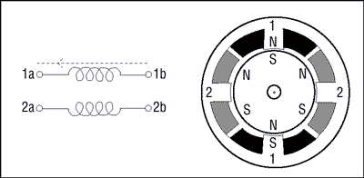
Fig.2.2.2 Bipolar and hybrid SD.
This simplification comes at the cost of a more complex reversal of the polarity of each pair of motor poles.
Stepper motors have a wide range of angular resolutions. Coarser motors typically rotate 90° per step, while finer motors can have 1.8° or 0.72° resolution per step. If the controller allows, then it is possible to use a half-step mode or a mode with a finer step splitting (micro-stepping mode), while fractional voltage values are applied to the windings, often formed using PWM modulation.
If only one winding is energized at any time in the control process, then the rotor will rotate through a fixed angle, which will be held until the external torque exceeds the motor holding torque at the equilibrium point.
To properly control a bipolar stepper motor, an electrical circuit is needed that must perform the functions of start, stop, reverse and change speed. A stepper motor translates a sequence of digital switches into motion. The "rotating" magnetic field is provided by appropriate switching voltages on the windings. Following this field, the rotor will rotate, connected by means of a gearbox to the output shaft of the engine.
Each series contains high performance components to meet the ever increasing performance requirements of today's electronic applications.
The control circuit for a bipolar stepper motor requires a bridge circuit for each winding. This circuit will allow you to independently change the polarity of the voltage on each winding. Figure 3.2.3 shows the control sequence for single step mode.
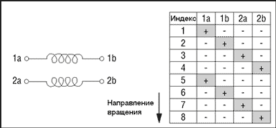
Fig.3.2.3 Control sequence for single step mode.
Figure 4.2.3 shows the sequence for half step control.
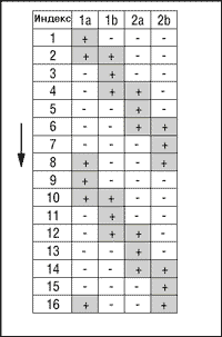
Fig.4.2.3 Control sequence for half step mode.
§1.3. Architecture of microcontrollers. Required parameters
MK is a microcircuit (chip, stone, IC) - which, in response to external electrical signals, acts in accordance with:
With features provided by the manufacturer
With electronics connected to MK
- with the program that we loaded into it.
The ability of MK to act according to our program is the essence of MK.
This is the main difference between MK and "ordinary" NOT programmable microcircuits. AVR- this is the MK family from the company ATMEL
,
developed taking into account the features and convenience of writing programs in the C language. Why AVR?
These are not expensive, widely available, reliable, simple, fairly fast, counting most instructions are executed in 1 clock cycle - i.e. at 10 MHz quartz, up to 10 million instructions per second are executed.
A  VRs have developed peripherals, i.e. a set of equipment surrounding the processor-computer in one MK housing or a set of electronic devices, blocks, modules built into the MK.
To control the stepper motor, an intermediate power switch is required to amplify the current pulses and a controller that provides both control of the stepper motor and interaction with the PC. The most understandable and suitable in terms of the required parameters can be considered an 8-bit microcontroller from AVR - AT Mega 8 with 8 KBytes of in-system programmable Flash memory, which has the following distinctive features:
8-bit high performance low power AVR microcontroller; progressive RISC architecture; 130 high performance commands; most instructions are executed in one clock cycle; 32 8-bit general-purpose working registers; completely static work; built-in 2-cycle multiplier; non-volatile program and data memory; 8 KB of In-System Self-programmable Flash memory; provides 1000 erase/write cycles; additional sector of boot codes with independent lock bits; the mode of simultaneous reading/writing (Read-While-Write) is provided; 512 bytes EEPROM; provides 100,000 erase/write cycles; 1 KB built-in SRAM, programmable lock; ensuring the protection of user software; built-in peripherals; two 8-bit timer/counters with separate prescaler; one with compare mode, one 16-bit timer/counter with separate prescaler and capture and compare modes; real time counter with separate generator; three PWM channels, 8-channel A/D converter (in TQFP and MLF packages), 6 channels with 10-bit precision; 2 channels with 8-bit precision; 6-channel analog-to-digital converter (in PDIP package); 4 channels with 10-bit precision; 2 channels with 8-bit precision; Byte-oriented 2-wire serial interface; programmable serial USART; serial interface SPI (master/slave); programmable watchdog timer with separate built-in oscillator; built-in analog comparator; special microcontroller functions; power-on reset and programmable voltage drop detector; built-in calibrated RC generator; internal and external interrupt sources; five power-down modes: Idle, Power-save, Power-down, Standby and ADC noise reduction; I/O pins and cases; 23 programmable I/O lines; 28-pin PDIP package; 32-pin package; TQFP and 32-pin MLF package; operating voltages: 2.7 - 5.5 V (ATmega8L), 4.5 - 5.5 V (ATmega8); operating frequency: 0 - 8 MHz (ATmega8L), 0 - 16 MHz (ATmega8).
These parameters largely satisfy the requirements for the implementation of a hardware-software complex, in connection with this, it was decided to use this particular microcontroller, both in terms of technical parameters and in all others, including its prevalence and familiar command architecture. The purpose of each leg is indicated in Appendix 1 in Fig. 1.3.1.
§1.4. Software environment for the microcontroller
When writing a program for the microcontroller, a C compiler CodeVisionAVR was used.
CodeVisionAVR- an integrated software development environment for microcontrollers of the Atmel AVR family.
CodeVisionAVR includes the following components:
C compiler for AVR; assembly language compiler for AVR; generator of the initial code of the program, which allows to initialize peripheral devices; module for interaction with the debug board STK-500; module of interaction with the programmer; terminal.
The output files of CodeVisionAVR are:
HEX, BIN or ROM file for downloading to the microcontroller using a programmer; COFF - a file containing information for the debugger; OBJ file.
CodeVisionAVR is commercial software. There is a free trial version with a limited number of features.
As of April 2008, the latest version is 1.25.9.
Data taken from Wikipedia.
The program code was originally developed in the C language. The C language is characterized by conciseness, a modern set of flow control constructs, data structures, and an extensive set of operations.
Xi(English) C) is a standardized procedural programming language developed in the early 1970s by Bell Labs employees Ken Thompson and Denis Ritchie as a development of the B language. C was created for use on the UNIX operating system (OS). It has since been ported to many other operating systems and has become one of the most used programming languages. C is valued for its efficiency; it is the most popular language for creating system software. It is also often used to create application programs. Despite the fact that C was not designed for beginners, it is actively used to teach programming. Subsequently, the syntax of the C language became the basis for many other languages. Data taken from Wikipedia.
§1.5. Software environment for the CNC machine control module at the PC level
Borland C++Builder 6 software environment was chosen as the basis for writing the CNC machine control software module. Borland C++Builder is a recently released rapid application development tool by Borland that allows you to create C++ applications using the Delphi development environment and component library. This article discusses the C++ Builder development environment and the basic techniques used in designing the user interface.
We will not dwell on a detailed description of the current development environment for the control module, since there are many tutorials and reference books on working in Borland C++ Builder. When creating the complex, textbook materials were used, and.
Also, when developing, writing and improving the software package, previously acquired skills and articles from the Internet, taken from sources, as well as from various forums, were used.
When writing programs for both the controller and the control module, the PROTEUS package testing complex was of considerable importance - an electronic device simulator that supports AVR, 8051, Microchip PIC10, PIC16, PIC18, Philips microcontrollers
ARM7, Motorola MC68HC11, complete design system. The ability to test, from an idea to the results of the device and files for the board.
An important role in such systems is played by the successful creation of a CAM system designed to solve the problem of generating control programs for processing parts on CNC machines. That is, the formation of control data blocks from the source information. In the current work, the source information is image files, vector hole files that need to be converted to the required command format.
Currently, the CAM system is a complex software package. Over the past decade, several generations of CAM systems have changed.
According to experts, a modern domestic CAM system that can withstand the best Western models should have the following characteristics.
Advanced tools for importing geometric models.
If the representation of a geometric model in the STL or VDA format has certain disadvantages related to the accuracy of the representation of the model, and the STFP format has not yet found proper distribution, then the use of the IGES standard is quite capable of solving this problem. Currently, the IGES standard is generally recognized and provides the transfer of any geometric information. It is supported by all modern computer-aided design systems.
Support for 3D objects in NURBS representation.
Representation of curves and surfaces in the form of rational splines, or NURBS, provides high accuracy and compactness of data storage. In addition, the latest CNC racks will have built-in NURBS interpolation. For this reason, most of the existing systems that work with approximated objects will face the need for significant improvement.
Support for 3D models of any complexity.
Modern CAM systems allow you to create surface and solid models of high complexity (for example, car body parts). The processing of such models is possible in the absence of quantitative and qualitative restrictions in the CAM system.
Means of access to elementary objects of the model.
The real model consists of many surfaces. The system should allow to operate with separate surfaces (or their groups), which is necessary to achieve optimal technological solutions.
Means of modifying the geometric model.
For the processing of technological equipment, a geometric model of the product is used. In this case, it is often necessary to modify the original model. In the best case, the system should have full-fledged 3D modeling tools, but the fulfillment of this requirement significantly affects the cost of the system.
Functions for constructing auxiliary geometric objects.
The optimal organization of the processing process may require performing operations on limited areas of the model, or, on the contrary, select “islands” for which processing is prohibited. The system must have the means necessary to construct the contours of the boundaries. Modern systems have no restrictions, both on the number of such boundaries and on their nesting. In addition, contours can be used to control the path of a tool.
Wide range of processing methods.
The possibility of choosing the optimal processing method can significantly facilitate the work of the technologist and reduce the processing time on the machine. In the recent past, CAM systems could get by with surface treatment along isoparametric lines. Today, models for which this method is applicable are among the simplest. The processing of real models requires more complex algorithms that provide, for example, tool movement along curves obtained by crossing planes with quasi-equidistant surfaces.
Automatic cutting control.
The construction of quasi-equidistant surfaces makes it possible to exclude gouging when calculating the tool path. However, from the point of view of the mathematical apparatus, this is the most difficult part of the program, if we do not take into account the approximated models.
Means of automatic identification of zones of underworking.
The presence of such funds can significantly facilitate the work of the technologist.
Developed means of managing the parameters of technological operations.
The operation execution mode can vary significantly depending on the selected parameters. The variety of tuning tools allows even with a small number of processing methods to obtain a large number of processing options. However, a large number of adjustable parameters significantly complicates the development and use of the system; therefore, it seems necessary to have means of automatically determining the values of the parameters of a technological operation, depending on the dimensions of the model, processing method, tool, etc.
Support for various types of cutting tool.
The system should not impose restrictions on the shape of the tool used. The fulfillment of this requirement significantly complicates the algorithms for constructing the tool trajectory.
Means of modeling the process and the result of processing.
The system generates a model of the machined part and its photorealistic image. This allows the technologist to quickly control the results of work and detect errors in a timely manner.
Postprocessor with means of customization for an arbitrary format of the control program.
The task of translating data from an intermediate format (eg CLDATA) is not particularly difficult. However, the variety of numerical control systems gives rise to the problem of ensuring compatibility with arbitrary equipment. The customization tools must be available at the user level.
Means of dynamic visualization.
A characteristic feature of modern systems is the presence of advanced visualization tools for a three-dimensional model. The use of technologies such as OpenGL or DirectX makes it possible to achieve a generation speed of up to several frames per second without the use of expensive hardware accelerators, which allows you to dynamically control the angle and scale of the image. To solve this problem, it is necessary to perform triangulation of the original model, which is not always easy, provided that a wide range of representation forms of three-dimensional objects is supported.
Modern user interface.
The level of a modern system is largely determined by the organization of the user interface. At the same time, the extensive functional composition is in conflict with the organization of convenient access to controls and turns interface design into a real art. A serious problem with older systems is the support of numerous atavisms of the user interface.
The listed set of requirements does not claim to be complete, but allows you to form the most general idea of the modern system.
The most famous domestic CAM modules are SprutCAM, Compass-CNC, Gemma-3D, etc.
The use of such systems is not considered, since for the purchase of such systems one should make significant financial contributions, as well as purchase equipment that is designed specifically for a specific CAM system, which is also very expensive. Therefore, it was decided to develop our own CAM - a system that will meet the requirements for solving the task.
Chapter II. Implementation of the necessary CNC machine control modules
§2.1. Physical model of the hardware
First of all, methods for creating a hardware-software complex with CNC were analyzed. When designing the mechanical part of the CNC machine, parts used in dot matrix printers were used. In particular, these are:
Guides with carriages;
Stepper motors;
Power microcircuits for stepper motor control;
Connectors and cables.
Guides with carriages were converted instead of bronze bushings to pendulum bearings, since movement on bronze bushings with the necessary loads is not possible due to the friction force and low power of the stepper motor. The bearings provide free movement along the X and Y coordinates even under significant loads (see Fig.2.1.1).
Rice. 2.1.1. – the use of pendulum bearings for travel carriages.
All parts were securely fixed on a chipboard sheet. To ensure the movement of the machine spindle along the Z axis, parts from an ordinary CD drive were used, in which a worm gear was used to move the laser over the disk (see Fig.2.1.2.).
Fig.2.1.2. – use of parts from the CD drive for the Z axis.
All the cables of the stepper motor and the spindle motor were routed to the connector that will be connected to the machine control board. The control board was assembled on the basis of the AT Mega 8 microcontroller on a circuit board with a programming connector and the necessary electronic elements and microcircuits (see Fig. 2.1.3.).
To test the hardware of the machine, a stepper motor control program for the microcontroller was written. The program algorithm consists in actuating all elements of the machine without the participation of a PC, that is, according to the commands embedded in the microcontroller.
Fig 2.1.3. – general view of the hardware complex with the circuit board.
Now there is a hardware and software part that controls the CNC machine in three coordinates without using a PC according to the algorithms and coordinates previously “stitched” into it.
§2.2. Data analysis and structure of the drilling file with *.drl.
At the first step, the hardware and software part was developed for drilling holes on the board for mounting microcircuits. To do this, an algorithm was developed that understands a specific technical data format for drilling holes. To accomplish the task, the data format with which the software package will work was determined. After analyzing the information on the Internet about CNC machines, the following conclusions were drawn: basically, all machines work with the help of purchased CNC control drivers and the “VriCNC” programs attached to them, which are developed abroad and cost a lot of money. But also from the received demo versions of programs and “samples” for the CNC, it was found that in most cases the generally accepted “Gerber” format working with G-codes is used to control the machines. Using resources it was obtained:
G-code is the name of the programming language for controlling NC and CNC machines. Created by the Electronic Industries Alliance in the early 1960s. The final revision was approved in February 1980 as the RS274D standard. During development, due to a huge lack of control over all the many functions and tools of machine tools, several CNC machine manufacturers adopted G-code as a standard. Additions and innovations in the G-code were made by the manufacturers themselves, so each operator must be aware of the differences between machines from different manufacturers.
Below is a simple Gerber file illustrating the structure and content of the format:
Then a search was made for applications that work with a similar format. Attention was focused on a common program Sprint layout designed for PCB designers. This program has the ability to export the results in the Gerber format we need. Now we can draw the necessary boards and export the result for drilling holes in *.drl format with G-codes.
Next, a method for analyzing the data structure in the resulting file was developed and the necessary data for drilling holes with a CNC machine were selected from it. Initially, it was decided to use several commands to work with the machine, which would indicate the necessary parameters, for example, these could be single-byte commands that would indicate that:
There will be a drilling operation;
There will be data on operating variables;
A block of coordinates will arrive;
End of operation.
A dialogue between the PC and the MK is also organized. Which provides an ordered two-way communication between each other with the ability to cancel the current operation.
Positioning by the machine is carried out based on the received coordinates in the format “X123456Y123456Z123…”. That is, the first three numbers make up the integer part of the number, the second three numbers make up the fractional part of the number, and the Z coordinate has only the integer part. But in the future, given the factor of distance per step of the stepper motor on the plane, only the number of steps for each coordinate and the necessary commands will be sent.
So, about the data structure in the *.drl file.
In a programme Sprint layout a board design with three holes was created. The inner diameter of the holes is set to 1 mm. The size of the fee is not critical. Then from the menu File->Export file->"Format Excellon" the drill export wizard is called. Set to "drill from print side" or from mounting side (inverted horizontally). The metric system of measurement is selected. In the "Number after the decimal point" field, the value 3.3 is selected and the checkbox for deleting zeros is unchecked, as shown in fig. 2.2.1.
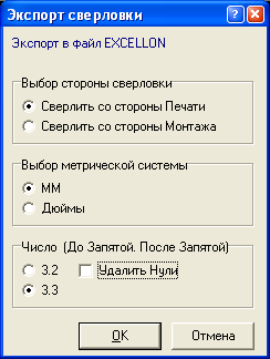
Rice. 2.2.1. – Export files for drilling.
This is in order to prepare the file in advance for more convenient conversion in the application for sending to the CNC. Pressed OK, the file name is specified and saved. For example, 123.drl. Then, opening the resulting file with any text editor, we have the following:
To accomplish this task, you need the following:
Reading data from a file into an array line by line;
Analysis of each readable line for the content of the text;
If the code G05 (command for drilling) is encountered, then we continue the analysis and read the coordinate data in 3.3 format and enter them into an array of numbers for the subsequent formation of a drilling view pattern.
If the code M30 (end of program) is encountered, then we complete the analysis of the file.
Here is an example of the implementation of this task in C ++ in the C ++ Builder environment:
§2.3. The algorithm for reading data in the microcontroller coming from a PC throughUART
To control the CNC machine using a microcontroller, a set of commands and data was formed that will be “understood” by the controller, a PCMK dialogue is provided. This is necessary in order to bypass the cause of the lack of memory on the MK. After all, the transferred volume can be much larger than the amount of RAM on the MK. To do this, it was decided to form a receive buffer on the MK of 255 bytes (255 characters - this is with a margin of 2-3 times) and after transmitting a data line, wait for confirmation of the execution of the previous command and a signal to allow the transfer of the next line. After analyzing all the necessary conditions, it was decided to develop an algorithm for receiving data on the controller, since the possibilities for implementing various methods are more limited on it.
The controller was initially programmed in the Code Visio AVR environment in C language. To avoid frequent reprogramming of the MK, the program was tested in the Proteus complex. However, during operation, differences in the output results in the proteus and, in fact, on the hardware, were often observed.
To solve the problem, the functions and procedures available in Code Visio AVR for working with input / output via UART were analyzed. The analysis was carried out on the basis of the task. It is necessary to receive a line from a PC, separate it from another line, read it, analyze it for content, if this is a command, then proceed further to the analysis of coordinate data. The main thing here is to choose the format of the received data correctly so that it is most convenient for using the available functions. At first, it was not possible to “correctly” read the data lines coming to the MK, since it is necessary to accurately determine the last character of the line. And also the reception and transmission in the MK is organized on interruption. And the data is stored in the same buffer, of which there are two - one for receiving, the other for transmitting. On the Internet, and in scientific sources, to solve the problem, functions were found that scan the received data, automatically highlighting the lines. For example, a function such as scanf(), which reads data from the input stream in the format specified in the first parameter and stores them in variables, the addresses of which are passed to it as the following parameters. For instance:
scanf(“% d,% d/ n”,& x& y); - we read two numbers in decimal form, which are separated by a comma, into the variables X, Y, respectively. But, as mentioned earlier, there is a problem regarding finding the end of lines, and this function does not work correctly with data that comes from the PC. It was decided to create "their own" procedure that generates strings from the incoming data. Below is the implementation of the string generation algorithm:
|
su=getchar(); if (su=="\n") sscanf(su,"G%d\n",&op); |
Let us describe this algorithm in more detail. We do not work directly with a receive character interrupt. The buffer is formed independently by interrupts and you should not load the buffer formation function with unnecessary operations. We, when we need it, calmly read characters from the buffer ( su[ ii]= getchar(); ) to the string su using the index array, and at the same time check the incoming character for the presence of a line terminator. If there is one, we scan the line for all the data we need, which may be in the received line. With the help of the procedure sscanf ( su ," G % d \ n ",& op );, which in this case scans the string su for the presence of the character 'G' and, if present, places it in a variable op the number in the string after the 'G' character.
Thus, it was possible to analyze the incoming data on the MC from the PC and perform various actions based on the received data. Several procedures have been added to the program code for the microcontroller to ensure the operation of such operations as drilling, machine initialization. All operations are controlled from a PC. Subsequently, burnout operations and manual control mode (Robot) were implemented.
§2.4. Formation of a drilling file to be sent to the microcontroller
To conduct a dialogue between the PCMK, an algorithm was organized for “communication” of the CNC machine with a PC via the RS232 interface, . For this, a dialogue is organized between the MC and the PC, using a certain set of control and information commands. Also, it was taken into account that the buffer size on the MK is 256 bytes. That is, when sending more information, data loss occurs and, as a result, an error occurs in the operation of both the CNC machine and the entire system as a whole. To do this, it was decided to send data to the MK in packets, the size of which would not exceed 256 bytes.
But we also need to know what to send. A list of commands that will be used to ensure the PCMC dialogue was compiled. For example, sent to the MK, the command G05 means that the drilling operation is starting, G22 – burning operation.
§2.5. drilling operation
To drill holes, you need to know the coordinates of the hole on the board and the depth of the drill. To save time and resources, we will also introduce the concept of the initial position of the drill, that is, if the working stroke of the drill is 100 mm, and the thickness of the board is only 3 mm, then there is no need to fully raise and lower the drill over the hole. The coordinate movement function on the MK is organized in such a way that when executed, the Z axis moves first, and then the X and Y axes. Therefore, the algorithm for drilling a hole on the MK will be as follows:
Received command G05 for drilling in the main cycle of the program;
We transfer control to the drilling procedure;
We expect a string with data on the initial position of the drill (ZN(value)) and enter it into the variable zn;
We expect a line with data on the maximum position of the drill (drill lowering depth - ZH(value)) and enter it into the variable zh;
We expect a line with the DRL1 command (drilling start) and transfer control to the drilling cycle;
We expect a line with the DRL0 command (end of drilling) and transfer control to the main program loop, having previously initialized the CNC machine, if there is no such line, then we execute further;
We expect a string with coordinates in the format “(value_X),(value_Y)” and enter them into the corresponding variables. We move the drill to the indicated position, the Z axis to the zn position, then turn on the drill motor, lower the drill to the zh position, and again point 6;
When testing this algorithm, it was not possible to achieve the same results as in the simulator on the controller. After many attempts to change the code of the program, it was possible to achieve the correct work on the "real" device, but I had to sacrifice the correct results in the simulator. This is due to a mismatch between the analysis of the end of the line of the simulator and the working application with the controller. The end result was successful and trial holes were drilled. When testing the drilling operation, it was found that the accuracy of the machine did not meet the required. After a series of tests, it was found that in one step of the stepper motor, the CNC machine spindle travels a distance of 1.6 mm. This means that it will not be possible to drill holes for industrial circuits, as the existing accuracy will not allow. It was decided to increase the positioning accuracy of the machine spindle. To do this, you need to increase the gear ratio from the stepper motor to the carriages. To do this, the existing gears were replaced with corresponding larger diameters. By replacing the gears with a quick mounting on top of the existing ones and with glue, as well as removing the stepper motor from the gear, as shown in fig. 2.5.1, several more drilling operations were carried out.
Rice. 2.5.1. - an increase in the gear ratio from the stepper motor to the carriages.
After the modernization of the machine, it was again not possible to achieve the desired accuracy. Now, in one step of the stepper motor, the spindle of the CNC machine moves a distance of 0.8 mm. This is not what I wanted, but it was decided to leave everything as it is.
In the board drawing program, objects of microcircuits and some components were added, then it was all imported through the application and sent to the machine for drilling holes on the getenax to get closer to the task. The existing error of the machine was partially compensated by software, using algorithms for rounding and taking into account the coefficient. After drilling the holes, the microcircuit entered the holes without effort. This fact once again convinced of the need to increase the accuracy of the machine.
During long testing, it was found that drilling errors sometimes occur. This is due to various factors such as noise immunity, software failure and various adverse factors. To avoid this problem, it was decided to organize a system for monitoring drilled holes and the ability to control erroneous operations with subsequent error correction. A procedure was written that organizes all the necessary functions for monitoring the integrity of operations, as well as all the necessary improvements. The main parameters for integrity analysis are taken from the controller from the data that arrives at the PC after each completed operation of the carriage movement. This data contains information about the current position of the CNC machine spindle. That is, in response, we should receive the same string that we sent, and if the strings are different, it means "error", and we add this string to the list of errors for subsequent correction. In this way, we have succeeded in achieving error-free drilling of holes. Further development of this item is planned. But let's leave that for future development.
§2.6. Manual mode
Next, a module was created that provides real-time control of the CNC machine with a set of various commands. The commands control various functions of the CNC machine. Among them, such as setting the speed, setting the step-half step mode, turning the drill motor on or off, moving the carriage in three-dimensional space, and others. All this was organized using a list of commands mutually understood by both the controller and the application, as well as using the already existing functions of procedures at the level of both the microcontroller and the PC level.
The description of the commands used is given below.
|
Description |
|
|
Command to call the manual control procedure |
|
|
Start procedure |
|
|
X carriage position |
|
|
Y-axis carriage position |
|
|
Carriage position in Z |
|
|
Delay time between phase pulses (global speed) |
|
|
Selecting half step mode - full step mode |
|
|
End of procedure |
|
|
Enable (1) disable (0) drill motor |
These commands are recognized by the controller and the necessary operations are performed in accordance with the commands. At the application level of sending these commands, the solution of the manual control problem was achieved as follows. The necessary visual elements for controlling the position of the machine spindle, switching on and off electric motors, changing modes, etc. have been created. When the values of any of the elements are changed, an existing command is sent to the MC upon activation of the handler for this event. In response, information about the current state of the machine is expected. Only after a successful response is received, it is again possible to send a data packet to the MC.
After testing this mode on a real device, it was found that the positioning of the machine is not always carried out in accordance with the control in the application. Since the parameter change event handler sends data only when the data on the application form changes. And sending a data packet occurs only after receiving confirmation of the previous operation. An operation, such as moving a carriage a certain number of steps, takes a certain amount of time to complete and causes certain data packets to be skipped. To fix this error, it was decided to either use a queue, which is not very efficient, or organize a timer in C ++ Builder, in which the data on the PC and the current position of the CNC machine will be checked.
§2.7. Burnout
After performing a series of tests in drilling and manual modes, the existing CNC machine was equipped, or rather, its spindle, with a head for burning on the material. Using the capabilities of the created machine, it is possible to perform burning using both the point method and the “drawing” method.
The point method is understood as the execution of the burning operation by point lowering the spindle head with a thermal tool at a given point, holding it at the point of contact with the material on which the burning is performed, then raising the spindle head and moving to another point in the plane and repeating the operation.
The "drawing" method is understood as the execution of the burning operation by moving a thermal tool on the surface of the material along a given trajectory with curved lines, straight lines, etc.
As a thermal tool, a head was designed, consisting of a mount and contact connectors for power wires on the one hand, a piece of nichrome wire on the other hand, made in the form of an acute angle. To power the "burner", an additional power adapter from the manual "burner" is used, connected by an additional wire only during the burning operation.
To perform this operation, the point method was chosen. The choice depends not only on one's own desire, but also on both technical and software reasons.
The technical reason is due to the fact that when the burning tool moves on the surface of the material, due to the uneven surface and insufficient rigidity of the tool, the tool is bent and the lines are distorted. This cause can be eliminated by making a more accurate and improved mechanical part of the machine.
There are currently only two software reasons that do not allow burning by the “drawing” method, which can be solved by changing the program code, both on the microcontroller and in the machine control software product.
At the microcontroller level, the solution to this problem is to improve the program code and add a module in which it is necessary to implement the method for drawing curved lines and straight lines.
In the CNC machine control software, it is necessary to implement a module for converting vector files (for example, *.dxf - the standard data format used in many software products for creating vector images in Gerber format) into a data block for sending to the microcontroller. The second option is to create a module for directly drawing curved lines, straight lines, circles, etc. and preparing a block of data to be sent to the microcontroller.
Programmatic reasons have not been resolved at the moment, mainly due to lack of time to implement the necessary methods and create modules.
To implement the point method, there is an almost ready-made drilling module, which has been slightly modified to perform the point-by-point burn operation. We will assume that the coordinates of the holes are the coordinates of the points, but instead of the drill, it is necessary to install the “burner” tool, and there is no need to turn on the drill, and the power to the “burner” is constantly supplied from a separate power source. Let us describe the algorithm for burning by points.
I-On the microcontroller:
Waiting for the command to burn out;
Obtaining the necessary parameters to perform the operation;
Waiting for a command to start receiving a block of data about points;
Obtaining data on the coordinates of the point for burning;
Moving the "burner" to the specified point;
Lowering the burner to the specified height for burning;
Time delay on the surface of the material for burning out;
Raising the burner to the initial (specified) height;
If the command for the end of the data block did not come, execute from step 4;
End of operation, machine initialization.
II- In the software package on the PC.
Scanning the image pixel by pixel and creating a block of data with the coordinates of each point, depending on the parameters set on the form, to send to the microcontroller.
Sending a data block from a PC to an MC in a dialog mode at the touch of a button with visualization of the process and keeping statistics on the execution of the burning operation.
Cancellation of burning at the touch of a button, as well as the ability to continue burning from a specified point.
The algorithm for burning by points, implemented programmatically on a microcontroller, will not be particularly considered, since it is almost similar to the algorithm for drilling holes, with the exception of some points:
As parameters, data on the initial position of the “burner”, on the height of the movement of the “burner”, on the delay time of the “burner” on the surface of the material are transmitted to the microcontroller.
The drill is not involved in the current operation, therefore, there is no need to turn on / off the drill motor.
To burn one point, you need to execute three commands, unlike two when drilling:
a) moving the machine spindle to the specified coordinate point;
b) lowering the burner on the surface of the material for burning;
c) raising the burner to the starting point and waiting for data on the next point.
We will consider the algorithm and software implementation of the point burning module on a PC in more detail.
First of all, the image is loaded into the TImage field. For this, the standard image loading dialog is used. To work, you need a pre-processed graphic file in *.bmp format. Pre-processing should be understood as bringing the image to shades of gray or black and white, as well as correcting brightness, contrast, to create a more efficient image. Image efficiency lies in creating the minimum number of dots to display the desired image. This requirement is due to the fact that it takes a certain time to complete the burning, and also intensive burning in one area will lead to the merging of the burnt points into one spot, which will worsen the visual perception of the finished product.
After uploading the image, it will appear in the field of the application for visual observation. Next, you need to analyze the information on the image to form a data block to be sent to the MC. To do this, it was decided to programmatically examine each pixel of the image for color information. In practice, this was implemented using the function ImageV->Canvas->Pixels[x][y], which returns the number and three components of the color palette. The smaller this number, the darker the pixel in the image. Using this function, it was decided to select only those points whose intensity can be set directly on the CNC control application form. For this purpose, a slider with limiting parameters in the form of numerical constants called Intensity was used. You can specify a selection of pixels ranging from black to all non-white pixels.
Scanning the image pixel by pixel, only the points that satisfy all the selected parameters are selected, we write the coordinates of the corresponding pixels to the data block for subsequent sending, while marking the selected points on the image in green. This functionality allows you to visually analyze the received data for burning. In case of dissatisfaction or other reasons, you can change the parameters and rescan the image with new selection parameters. It is also possible to specify the scale of the transferred image, this is not visually reflected, but you can see the difference in the data to be sent to the MK. To set the scale, the "Scale" slider was used with a choice from 10% to 400%. The appearance of the module is shown in fig. 2.7.1.
After the formation of the data block, data is displayed in the designated field, which are almost ready to be sent to the MK. Further, by pressing the button, a data block is sent with the command to burn and with the parameters necessary to perform the operation. The burning command is a text string "G22\n", followed by data about the starting point, the point of reaching the processing surface, the time delay and sending the string "DRL1\n", indicating that data about the coordinates of the points will now be transmitted. And then the timer for conducting a dialogue between the MP and the PC is turned on, each subsequent line will be sent only after receiving confirmation of the execution of the previous command in the form of a coordinate string about the position of the spindle in the coordinate plane.
Rice. 2.7.1. – appearance of the burning module.
Stopping the current operation can be done when sending a string "DRL0\n", the pause can be done by pausing the conversation timer. The media control panel is used to perform these operations. Also added the option to continue from the specified point. Logging is supposed to be able to automatically continue the operation in case of various failures in the operation of both the machine and the computer.
At the first stage of testing the burning module, the same shortcomings were found as during drilling. We are talking about the positioning accuracy of the machine, or rather about the resolution. As mentioned earlier, the minimum distance that the machine spindle can be moved is 0.8 mm. That is, the distance between pixels on the transferred material is about 0.8 mm, depending on the diameter of the burning tool. The issue of improving the machine and software modules to increase accuracy has become even more relevant.
§2.8. Modernization of the CNC complex
Previously, the modernization of the machine was described, which consists in increasing the gear ratio from the stepper motor to the carriage movement belts in the X and Y coordinates. Now, having analyzed the stepper motor control module on the microcontroller again, it was decided to increase the accuracy programmatically. First of all, the expected result of this event was analyzed. Theoretically, the task was set: to reduce the minimum distance of movement of the machine carriage from 0.8 mm to 0.2 mm, which would satisfy most needs in various operations. That is, the accuracy of the machine is supposed to be increased by 4 times.
Let's analyze the existing stepper motor control algorithm for moving to a certain minimum angle currently available.
This subroutine is called when the stepper motor needs to be rotated to move the X-axis carriage forward one step. It can be seen from the cycle that for this it is necessary to send 4 pulses, as described in the theory of stepper motor control. If only one impulse is given for one call to control the stepper motor, then the angle by which the stepper motor will turn will be reduced by 4 times, and therefore the distance traveled by the machine spindle in the coordinate plane.
It remains only to change this stepper motor control module. To do this, it is necessary to remember the position when applying an impulse, so that at the next call, apply the “correct” impulse in order to avoid violation of the stepper motor rotation control scheme. What was done:
In the subroutine, a new variable bx was introduced, which performs the function of saving the position. 4 pulses - 4 possible values in the additional variable. When applying one pulse - the value of bx is increased by 1 and the next time the subroutine is called, the "desired" pulse will be given. When 4 pulses are reached, the variable is reset to zero and the pulse cycle will continue according to the pulse table for stepper motor control. The subroutine for moving the carriage in the opposite direction has also been changed. Only the stepper motor control routines in full step mode have been changed. In case of successful testing, the stepper motor control subroutines in the half-step mode will also be changed.
The microcontroller was re-flashed with an updated version of the program code. When power was applied, the machine initialized successfully. The image for the burning operation is loaded, scanned, parameters are set, the start button is pressed. After several tens of lines, a strong distortion of the image on the transferred material was detected. All parameters were re-checked, the image was changed, the start button was again and the machine was not working correctly again ...
After several tests, after analyzing the situation, it was found that the reason was the wrong control of the stepper motor. This is due to the inconsistency in the supply of the “necessary” impulses when changing direction from direct to opposite. This is due to the incorrect organization of the stepper motor control cycle in the opposite direction. Theoretically, an algorithm was developed to control the stepper motor in the opposite direction from any moment of control in the forward direction of the carriage. Accordingly, the necessary sections of the subprogram were changed. Here is an example of moving the carriage along the X axis in the opposite direction:
Comparing with the previous fragments, it can be seen that the variable bx does not increase, but decreases, and the phase order is selected in accordance with theoretical calculations.
The microcontroller was "flashed" again, initialization, testing, and a successful result. The goal was achieved, now the positioning accuracy is 4 times higher, and from the original result 8 times, and in one step, the spindle travels a distance of 0.2 mm.
After a few more tests on the machine, it was again proved that for some operations, half-step control is necessary, since a large amount of machine movement power is needed, mainly in the X-axis, since this is the most loaded part of the machine.
Theoretically, using the control in half step mode, in the same way it is possible to increase the accuracy by another 2 times, but then it becomes necessary to constantly hold the pulse on certain phases as indicated in the stepper motor control table in half step mode, which leads to overheating, like the motor windings, and power drivers to control them. Therefore, it was decided to control the stepper motor in the half-step mode with double pulses, thereby freeing the phases from loads. At the same time, positioning accuracy is maintained.
|
for(i=1;i<=ar;i++) ( //half step pulses X Axis Forward case 0: PORTD.7 = 0; PORTD.4 = 0; delay_ms(sleep); //1001 PORTD.7 = 1; delay_ms(sleep); //0001 PORTD.4 = 1; bx++; break; case 1: PORTD.4 = 0; PORTD.5 = 0; delay_ms(sleep); //0011 PORTD.4 = 1; delay_ms(sleep); //0010 PORTD.5 = 1; bx++; break; case 2: PORTD.5 = 0; PORTD.6 = 0; delay_ms(sleep); //0110 PORTD.5 = 1; delay_ms(sleep); //0100 PORTD.6 = 1; bx++; break; case 3: PORTD.6 = 0; PORTD.7 = 0; delay_ms(sleep); //1100 PORTD.6 = 1; delay_ms(sleep); //1000 PORTD.7 = 1; bx=0; break; |
In this way, a sufficient accuracy has been achieved, which will also greatly expand the capability of the hole drilling module in terms of accuracy. Having practically calculated a new coefficient of the number of “steps” of stepper motors from the distance traveled, changes were made to the constants of the software product for controlling stepper motors from a PC.
Chapter III. Analysis and testing of the complex
§3.1. Testing the CNC complex in computer simulation complexes
When designing a hardware-software complex, an important role at the first stage is played by testing in programs that emulate the real operation of the device. For the main emulation complex, the “Proteus” testing package was taken, which allows you to work with circuits of any complexity and the ability to emulate the microcontroller firmware program. The package for emulating electronic devices allows you to bypass all sorts of errors during the subsequent construction of a real hardware-software complex. The huge advantage of this testing method is the ability to check the "firmware" without flashing the microcontroller with a programmer. Indeed, when setting up and designing a complex, it is necessary to repeatedly change the program code, and testing on a real complex shows the need to change one or another code subroutine for the microcontroller.
One disadvantage of this testing package, which was the most unfavorable during operation, is a slight inconsistency in the functioning of the complex. This is due to the inconsistency of certain intermediate interaction commands, for example, some factory features of microcontrollers that were not taken into account by the package developers, as well as a slightly different exchange interface between the UART terminal in the Proteus and on the computer.
In PROTEUS, a model of interaction between nodes and devices of the CNC complex was modeled, which included:
microcontroller;
UART terminal;
Necessary "buttons", switches, etc.;
LEDs for indication of stepper motor phases.
It was decided to use LEDs instead of existing stepper motor models in order to be able to control each impulse for the correct operation of the stepper motor. The emulation complex is shown in Figure 3.1.1.
Rice. 3.1.1. – appearance of the complex in PROTEUS.
To be able to visualize the correct operation in the Proteus, large time delays were previously set in the program code for the microcontroller. This allows you to properly control the operation of all nodes of the complex. Upon successful testing, the changed parameters were restored to the original ones.
§3.2. Drill module testing
The first hole drilling module was developed using the EXCELLON data format described earlier. When starting a program that implements control of the CNC complex, this module is active by default, or if it is not active, you can select it using the page selection of modules (Page Control). First of all, you need to connect all the connecting wires of the hardware to the PC and supply power to the CNC machine. Next, open the switched port of the RS-232 interface. By pressing the download button, the download dialog prompts you to select a *.drl file. We select the previously created drilling file in the PCB drawing program, and open it. Below the button, information about the name of the current file appeared. Now you need to analyze the open file, for this we click on the logically understandable button in the form of arrows to the right. By pressing the button, the file is processed, which will naturally take one or another time interval. With a small number of holes, this interval is insignificant. When creating one or another simple scheme, the number of holes will not exceed 200-400 holes. Indeed, even circuits with about two hundred holes imply the placement of about 10 AT Mega 8 microcontrollers and the necessary elements, or about 15 K155 series microcircuits.
But for testing, a diagram was drawn, on which, as it later became known, there are 1243 holes, which is very suitable for testing the complex. The analysis of such a file was carried out in less than a second. This time interval also depends on the performance of the computer. But when working on different computers, it is not very distinguishable. After the file is analyzed, a data block is placed in the Memo field to be sent to the hardware of the complex, and green dots are marked on the image in the form of a coordinate plane, indicating holes for drilling - fig. 3.2.1.
You also need to specify the parameters for the correct operation of the device. These are the start position of the drill, the working depth of the drill, the starting point of the board and the size of the board. This data will affect how the machine works. The main parameters are the starting position of the drill and the working depth of the drill. The start position determines the position of the drill in the OZ plane above the surface to be machined. And the working depth is the distance that the drill will lower or rise. When drilling, it is necessary to experimentally achieve optimal parameters. After all, the smaller the amount of lowering of the drill, the faster it will be drilled, that is, you need to set the initial position as close as possible to the surface being machined.
Rice. 3.2.1. – drilling module.
So, the “Drill” button is pressed, the characteristic noise of the machine, both when moving and when drilling. This means that the complex is working. Drilling is quite fast, in contrast to the presented speed mode when drilling holes. This threatens either to break the drill, or break the lowering mechanism. Therefore, the question arose of establishing different speeds of lowering the drill, and even better - drilling a hole in several lowerings. This is not yet allowed due to temporary reasons. But it was decided, when drilling deep holes, to perform the operation in two or more passes, each time increasing the height of the lowering of the drill.
To the left of the drilling module, the information panel displays the start time of the operation, the elapsed time from the start of the operation, and additional data about the current operation.
When drilling holes, points that have already been drilled are marked in red. The line is sent, waiting for a completion response, then the next one is sent. In the error field, lines that are not executed due to errors during data transfer will be placed. However, the exchange interface is organized in such a way that errors are almost irrelevant. But there may be errors in the processing of receiving data, errors were noticed while waiting for a response from the hardware. A line with data on the completed coordinates should come, but an empty line comes, until this shortcoming is resolved due to the failure to identify the cause. But this is compensated by error control, which, in case of a mismatch of commands, will issue the corresponding information.
It took about 2 minutes to drill about 100 holes and not a single mistake.
§3.3. Manual control
The manual control module is designed to test the maximum possible functions in manual mode, controlling each part of the machine separately. During the development of other modules, the manual control module helped to test certain functions of the machine, for their application in other modules. For example, changing the time delays helped to set the optimal value of the parameters, which ensures fast and silent movement of parts of the hardware complex with minimal vibrations.
The transfer of control commands is activated when the "Start" button is pressed. When operating the machine in the manual control module, some shortcomings were identified. This is sending commands multiple times while moving the sliders slowly. Such shortcomings are solved programmatically. Thanks to this module, the coefficients for the remaining control modules were calculated, since the control is performed step by step. The use of the manual control module for setting the initial parameters when performing other operations is also calculated - fig. 3.3.1.
Rice. 3.3.1. – Appearance of the manual control module
§3.4. Burnout
The burning module is made on the basis of the drilling module, that is, the control algorithm is similar. The difference is the functionality of the operation and the source data. Unlike drilling, burning requires many more operations than drilling.
As you know, the module scans the image pixel by pixel. For example, to scan an image with a resolution of 300*300 pixels, 90,000 pixels need to be analyzed. This takes much longer than drilling. And the inconvenience is the process of scanning a large image, when there is a feeling of the application freezing.
We load the image by pressing the button, stick it out, open it, it appears in the corresponding window of the module. The size is immediately displayed in the appropriate fields, in our case 87 * 202, and the total number of points is automatically calculated - 17574. The "Analysis" button becomes active. We press for about 7 seconds, in accordance with the parameters, the selected pixels are painted over in blue - fig. 3.4.1.
Rice. 3.4.1 - image analysis in the burning module
In the corresponding field, we see that 2214 points are selected. This is much more than when drilling. Having specified the parameters, which are almost the same as when drilling, in contrast to the delay time of the “burner” on the burnout surface, we press the start button. For burning, first, it is necessary to install a burner on the machine and connect power to it (Fig. 3.4.2.).
Rice. 3.4.2. - transferring the image to the tree by burning.
When transferring the current image as a girl's outline onto a sheet of plywood, it took about 22 minutes. This time depends both on the initial parameters and on the size of the transferred image. During testing, a pattern of 297 X 400 in size was transferred, the total number of points was 118,800, while analysis with an average intensity was 22,589 points. And the transfer of the image with a “burner” to the material took about 6 hours - fig. 3.4.2.
Rice. 3.4.2 - testing with a large number of points
But during the burning, the computer crashed, and the process stopped with a power outage on the hardware of the complex. And when the power is turned on, the microcontroller is rebooted and initialized with the installation of coordinates at the starting point. It's good that the operation is almost over. Therefore, the question is about logging and using the previously described manual control module to set the initial position. And also to improve the hardware of the complex for "remembering" the last position with the implementation of the sleep mode.
Compared with testing the burnout module with the previous spindle movement resolution of 1 mm, the current resolution, which is 4 times larger, showed excellent burnout quality. Also, it would be nice to control the intensity of each pixel, indicating the delay time with each command. This would allow the image to be displayed with a wide range of hues, which would greatly beautify the burnt image.
Also, when testing other images, it was found that when transferring the image to the material, the image is inverted. That is, it is necessary to programmatically compensate for the horizontal inversion when transferring the image. But in general, the result of the burning operation pleases with the results obtained (Fig. 3.4.4).
Rice. 3.4.4. – testing of the complex for 24 hours a day.
During burning, completed points are marked on the image in the burning module. There is also a lack of information about the actual size in millimeters of the transferred image, since one pixel of the image corresponds to 0.2 mm in the transferred image, which is also solved programmatically.
In addition to the application, a user manual was developed, which can be called from the Help context menu. This manual covers the main points of machine control and program operation. Almost any user will be able to find the answer to a particular question that arose while working with the complex by reading the manual. However, the program interface is designed in such a way that everything is intuitive and simple, excluding minor settings and parameters.
Conclusion
When designing the CNC complex, many problems were solved, and some of them remained not fully resolved. Most importantly, it was possible to demonstrate the use of numerical software methods for the implementation of large complexes using CNC.
A hardware part was developed that ensures the interaction of all step motors, carriage end position switches, control board and PC via the RS232 interface. The software part is implemented in such a way that it is possible to control all the nodes of the machine, and also, thanks to the open code with comments, expand the functionality and upgrade existing control modules.
Testing of the complex made it possible to objectively assess the result of work on this project. As already mentioned, there are pros and cons. The advantages include:
Functioning of the complex as a single CNC system;
Implementation of several functions based on the CNC machine;
Detailed open code of any module that ensures the operation of the complex:
The possibility of improving and expanding the functional operations of the complex;
Flexibility of the complex and standardization of exchange interfaces between devices;
The following points were attributed to the minuses:
Incorrect calculation of the necessary time for the implementation of the initially set tasks;
Lack of independent power supply of the controller to prevent failures at the controller level;
Lack of software solutions to speed up the processing of initial data.
As well as some other minor shortcomings that are associated with the ease of use of the complex, but which are not so easy to solve due to the complex technical level of the complex.
After analyzing all the positive and negative points, we can say that, in general, the work is worthy of further consideration and expansion of the functionality of the CNC complex.
Perhaps this complex will be taken as a basis for the implementation of a complex of 3-D processing of surfaces and parts, as well as the implementation of various algorithms for constructing figures and curved lines. This will allow creating a hardware-software complex close to the CAM system. 3-D surface treatment can be applied in plaster milling to create three-dimensional sculptures, as well as in the manufacture of non-planar parts, in the first stage, the processed material can be foam. In the future, the use of a laser on the machine spindle may be considered. This will make it possible to perform complex operations, such as making three-dimensional parts, by burning a point at the intersection of 2 lasers or at a certain depth.
Additionally, it is possible to implement an engraving complex, both for glass and for granite, marble, wood, loose metals. There are many opportunities for such complexes, this is due to the flexibility of software tools on a computer and is limited only by creativity and investment in the development of CNC complexes.
Used Books
Development information and reference system for accounting for wagons on the access road of the enterprise
Thesis >> Informatics... numerical Operation code Key_Gruz numerical Code Weight numerical Weight N_dor_ved numerical ... Control produced similarly management ... hardware funds When choosing hardware funds for development software... as a separate devices with an opportunity...
Programmatically-hardware data protection
Synopsis >> InformaticsUnlike program protection. Programmatically-hardware means ... network) is used for management blocking devices with the exchange of information ... assigns a specific development software product and... is numerical ID accepting...
Programmatically-hardware complex for a multifunctional meteorological radar based on
Abstract >> Informatics1.3. OTHER DEVICES ON CHIP 11 1.4 SYSTEM SOFTWARE-HARDWARE DEBUG TOOLS... order of magnitude. Device shear exercises control numerical formats, including... incrementing starts over. 3.2 Development Windows Apps Before...
Software personal computer software (2)
Test work >> Informatics, programming... hardware partly provide drivers. Drivers - programs that expand the capabilities of the OS by management devices... high-volume computing numerical and text data, ... programs, software provision of basic funds development, hardware platforms,...
An P., "Pairing a PC with external devices", Per. from English. - M.: DMK Press, 2001. - 320 p.: ill.
Anuryev V.I. Handbook of the designer-machine builder. In 3 volumes. Moscow. "Engineering". 2001.
Deitel H., Deitel P., How to Program in C++ - 1001 p.
Dunaev P.F., Lelikov O.P. Design of units and parts of machines, M. Higher school, 1985.
Korovin B.G., Prokofiev G.I., Rassudov L.N. Program control systems for industrial installations and robotic complexes.
Kuzminov A.Yu. RS232 interface. Communication between computer and microcontroller. - M.: Radio and communication, 2004. - 168 p.: ill.
Levin I.Ya. Handbook of the designer of precision instruments. Moscow. OBORONGIS. 1962.
Litvin F.L. Design of mechanisms and parts of devices. Leningrad. "Engineering". 1973.
Morton John, AVR microcontrollers. Introductory course, trans. from English. - M .: Publishing house "Dodeka - XXI", 2006. - 272 p.: ill. (Series "World Electronics").
Orlov P.I. Design basics. In 3 volumes. Moscow. "Engineering". 1977.
Under the editorship of Academician Emelyanov S.V. Management of flexible production systems. Models and algorithms.
Edited by Makarov I.M. and Chiganova V.A. Control systems of industrial robots.
Under the editorship of Professor Sazonov A.A. Microprocessor control of technological equipment of microelectronics.
Directory. Instrument ball bearings. Moscow. "Engineering". 1981.
Metalworker's Handbook. In 5 volumes. Ed. Boguslavsky B.L. Moscow. "Engineering". 1978.
Fadyushin L., Musician Ya.A., Meshcheryakov A.I. etc. Tool for machine tools with ChPU, multi-purpose machine tools. M.: Mashinostroenie, 1990.
Shpak Yu.A. Programming in C for AVR and PIC microcontrollers - K .: "MK Press", 2006 - 400 p., ill.
http://avr123.nm.ru/ - microcontrollers AVR, description, instructions. hardware... into packages development control programs for CNC equipment ( numerical software control). COMPASS...
Control systems for automated process equipment
The most important part of any automaton is the system and control mechanisms. One of the most important defining features of modern ATO processing and assembly of electronic components is the type of control system that implements a given work program, coordinates the operation of all ATO mechanisms and devices during the working cycle and performs a number of additional functions.
General information about the program control of machines
Improving the productivity and quality of work on metal-cutting machines is associated with the mechanization and automation of the processing cycle and workpiece.
A control program is a set of commands in a programming language that corresponds to a given algorithm for the operation of a machine tool for processing a particular workpiece.
Depending on the method of setting dimensional information, all machine control systems are divided into analog (non-numeric) and numeric. Analog control systems convert the initial information embedded in the program carrier in the pre-production process. Program carriers can be: stops located in a certain way on the machine, copiers, cams and camshafts. The executive bodies of the machine, according to the initial information presented in the form of an analogue of the displacement program, reproduce this program for processing the workpiece.
Analog control systems are classified into the following types: closed, open, copier with a servo drive.
Closed-loop control systems control the executive body of the machine along the path (track), time (temporary), speed, power, pressure and other parameters.
Control systems driven by a copier, cam, ratchet and others that carry out a dosed movement of the executive bodies of the machine, as well as systems without a power amplifier (copy direct action) are classified as open.
Copier systems with a servo drive (hydraulic, electro-hydraulic or electric) have found wide application in machine tools of various types. These systems have mechanical or electrical feedback.
As an example, consider the operation of a copier control system with a hydraulic servo drive having mechanical feedback (Fig. 1), used on a lathe for manufacturing a shaped part 5 from a workpiece 4 along a copier 8. The hydraulic pump, during system operation, supplies oil under pressure PH into the right cavity of the hydraulic cylinder 1, and its left cavity is connected to the drain pipeline Pc. As a result of the pressure difference, the piston of the hydraulic cylinder 1 with the rod will begin to move along the Z axis, dragging the rod of the servo hydraulic drive 2. The throttling hydraulic distributor 7 is connected to the pressure PH and drain Pc pipelines. Longitudinal movement (along the Z axis) of the probe 9 along the copier 8 causes the valve 7 to move relative to the body in which it is placed. The separation of the probe 9 from the working surface of the copier 8 excludes the spring 6 of the hydraulic distributor. As a result of the movement of the valve relative to the body of the servo hydraulic drive 2, the throttling slots formed by the body and the valve are opened. Cavities A and B of the hydraulic cylinder are connected respectively to the pressure and drain pipelines. The pressure drop on the piston of the servo hydraulic drive 2 causes the drive housing to move behind the throttling hydraulic distributor 7, i.e., the movement of the probe along the copier is monitored. The movement of the body of the hydraulic drive 2 is transmitted to the cutter 3 rigidly connected to the body.
Rice. 1. Copy control system with hydraulic servo drive and mechanical feedback: 1 - hydrocylinder; 2 - hydraulic drive; 3 - cutter; 4 - blank; 5 - shaped part of the part; 6 - spring; 7 - hydraulic distributor; 8 - copier; 9- probe
Thus, the cutter 3 receives a longitudinal movement (along the Z axis) from the hydraulic cylinder 1, and a transverse movement (along the X axis) - from the hydraulic drive housing 2.
Copy systems are widely used to control the processing of a part in one, two and three coordinates. The ability to quickly change the program carrier (copier) allows them to be used in mass production.
Analog control systems increase productivity in machining, but do not provide sufficient flexibility. This causes the high cost of equipment changeover.
The evolution of numerical control technology took place in close connection with the development of computer technology and depended on it. Without the automation of computer programming of CNC systems, it would be impossible to compose control programs for processing many types of parts. In addition, computers make it possible to improve and facilitate the CNC programming procedure using methods such as interactive computer graphics and speech input of programs.
1. CNC from a computer, or machine numerical control (MCNC).
2. Direct digital control (DCU).
3. Adaptive control (AC).
In CNC systems from a computer, or MNC, traditional control devices, implemented on the basis of non-tunable (“hard-wired”) equipment, are replaced by a small (mini or micro) computer. This small computer is used to perform a number of basic CNC functions with the help of programs stored in its main memory. One of the distinguishing features of the MNC is that here one machine is controlled by one computer.
In contrast, another type of computer control, direct digital control (DNC), uses one mainframe computer to control several separate CNC machines.
The third type of control - adaptive control - does not require the use of an additional digital computer for its implementation. Machining with adaptive control involves measuring by the control system one or more variables characterizing the machining process (for example, cutting forces, temperature, power consumption, etc.), and the corresponding change in feed and/or cutting speeds to compensate for unwanted deviations of variables controlled process. The purpose of this mode is to optimize the machining process, which the control itself cannot provide. Many early designs of adaptive control systems were based on analog control devices. Modern systems of this type use a microprocessor.
CNC hardware
CNC hardware technology has changed radically over the years. At least seven generations of control equipment can be distinguished:
1. Vacuum tubes (circa 1952).
2. Electromechanical relays (circa 1955).
3. Discrete semiconductor elements (circa 1960).
4. Integrated circuits (circa 1965).
5. Direct digital control (circa 1968).
6. CNC from a computer (circa 1970).
7. Microprocessors and microcomputers (circa 1975).
Numerical control for automated equipment
The terms and definitions of the basic concepts in the field of numerical control of metal-cutting equipment are established by GOST 20523-80.
Numerical machine control (CNC) - control of the processing of the workpiece on the machine according to the control program, in which the data is given in digital form.
A device that issues control actions on the executive bodies of the machine in accordance with the control program and information about the state of the controlled object is called a numerical control device (CNC).
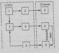 |
|
Distinguish between hardware and programmable CNC. In a hardware (NC) device, the operation algorithms are implemented in a circuit way and cannot be changed after the device has been manufactured. These devices are produced for various groups of machine tools: turning ("Kontur-2PT", H22), milling ("Kontur-ZP", NZZ), jig boring ("Size-2M", PZZ), etc. Such CNCs are manufactured with the input of the control program on punched tape. In programmable devices (CNC), algorithms are implemented using programs entered into the device's memory and can be changed after the device is manufactured. CNC devices include a small computer, RAM and an external interface.
A numerical control system (CNC) is a set of functionally interconnected and interacting hardware and software tools that provide CNC with a machine tool.
The main function of the CNC is to control the feed drives of machine tools in accordance with a given program, and the additional ones are to change tools, etc. In fig. 111 shows a generalized block diagram of the CNC. The circuit works as follows: the program input device 1 converts it into electrical signals and sends it to the program processing device 7, which, through the drive control device 8, acts on the control object - the feed drive 4. The moving part of the machine associated with the feed drive 4 is controlled by sensor 5 included in the main feedback circuit.
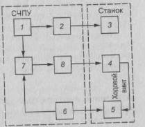 |
From the sensor 5, through the feedback device 6, information enters the device 7 for working out the program. Here, the actual displacement is compared with the one specified by the program in order to make appropriate adjustments to the displacements being made. Device 1 also sends electrical signals to device 2 to implement additional functions.
The device 2 acts on the actuating elements 3 of the technological commands (motors, electromagnets, electromagnetic clutches, etc.), while the actuating elements are turned on or off. The advantage of CNC machines is a quick readjustment without changing or rearranging mechanical elements. It is only necessary to change the information entered into the machine and it will start working according to a different program, that is, to process another workpiece (part). The high versatility of CNC machines is convenient in cases where you need a quick transition to the manufacture of another part, the processing of which on conventional machines requires the use of special equipment.
|
|
|
|
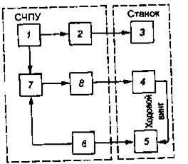
|
|
|
|
Rice. 2. Generalized block diagram of the CNC: 1 - program input device; 2 - device for implementing additional functions; 3 - executive elements; 4 - feed drive; 5- sensor; 6 - feedback device; 7 - program processing device; 8 - drive control device
The accuracy of the dimensions and shape of the workpiece, as well as the required surface roughness parameter, are ensured by the rigidity and accuracy of the machine, the discreteness and stability of positioning and correction input, as well as the quality of the CNC.
Structurally, CNC systems are open, closed and self-adjusting; by type of motion control - positional, rectangular, continuous (contour).
Open-loop CNC systems use a single stream of information. The program is read by the device, as a result of which command signals appear at the output of the latter, which, after conversion, are sent to the mechanism that moves the executive bodies of the machine (for example, calipers). There is no control over the compliance of the actual displacement with the given one.
In closed control systems, two information streams are used for feedback. One stream comes from the reader, and the second - from the device that measures the actual movement of the calipers, carriages or other executive bodies of the machine.
For self-adjusting systems (CNC), the information coming from the reader is corrected taking into account the information coming from the memory block about the results of processing the previous workpiece. Due to this, the accuracy of processing is increased, since changes in working conditions are stored and generalized in the self-tuning devices of the machine's memory, and then converted into a control signal. CNC differs from simple CNC controls by automatically adapting the workpiece processing process to changing processing conditions (according to certain criteria) for better use of the capabilities of the machine and tool. Machine tools with a simple CNC run the program without taking into account the action of random factors, such as allowance, hardness of the material being processed and the condition of the cutting edges of the tool. CNC, depending on the task and methods for solving it, are divided into control systems for any parameter (for example, cutting speed, etc.) and systems that maintain the highest value of one or more parameters.
CNC systems that provide precise installation of the actuator to a given position are called positional. The executive body in this case in a certain sequence bypasses the given coordinates along the X and Y axes (Fig. 3, a). In this case, the installation (positioning) of the executive body at a point with given coordinates is first performed, and then the operating time is performed. A variety of positional CNCs are rectangular CNCs, in which not points are programmed, but separate y and cuts, but the longitudinal and transverse feeds are separated in time.
CNC systems (Fig. 3, 6) that provide sequential switching off of the longitudinal and transverse feeds of the machine when processing a stepped surface are called rectangular. These CNCs are used in turning, carousel, turret, milling and other machines. The processing of stepped shafts and other parts with rectangular contours is performed only along a trajectory parallel to the direction of movement of the working bodies.
CNC systems (Fig. 3, c), which provide continuous control of the working bodies in accordance with the given laws of changing their path and speed of movement to obtain the required processing contour, are called contour. In this case, the tool moves relative to the workpiece along a curved path, which is obtained by adding movements along two (flat curved path) or three (spatial curved path) rectilinear coordinates. Such CNCs are used in turning and milling machines in the manufacture of parts with shaped surfaces. The feed s of the tool at each moment of processing is the sum of the transverse S
and longitudinal feed. Therefore, tool movements along different coordinate axes are functionally related to each other.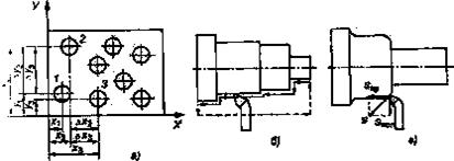
Rice. 3. Types of processing when using positional (a), rectangular (b) and contour (c) CNC: 1, 2, 3 - numbers of holes being machined;
and - coordinates of the holes along the X and Y axes;Computer Numerical Control
The MNC system uses in exclusive mode a computer with a program recorded in it to perform some or all of the basic functions of numerical control. For a number of years, minicomputers have also been used in MNC devices.
In appearance, an MNC machine is very similar to a conventional CNC machine.
Rice. 4. General configuration of the machine numerical control system (MCNC).
The part control program is first entered in the same way. Compared to conventional CNC systems, CNC systems have greater flexibility and increased computing power. New options for the functioning of the system can be introduced into the MNC device by simply replacing its program of work. Due to the possibility of reprogramming (this applies to both part control programs and system control options), the MNC is often called a flexible programmable CNC. The general configuration of the MNC system is shown in fig. 4.
MNC functions
The MCPU system is designed to perform a number of functions. The main functions of the MNC are as follows:
1. Machine control.
2. Compensation for deviations in the processing of parts.
3. Providing enhanced capabilities in programming and operation modes.
Diagnostics
Machine control. The main function of the MNC system is to control the operation of the machine. This involves the transformation of the commands of the control program for processing the part into the corresponding movements of the tool, implemented by means of a servo system that is connected to the computer interface. The ability to conveniently enter many different control functions into such a programmable controller is the main advantage of the MNC.
In the hybrid machine numerical control system shown schematically in fig. 5, the control device includes a reprogrammable part (computer) and "hard-wired" logic circuits implemented in hardware. The hardware components do what they do best (such as feedrate shaping and circular interpolation). The computer handles the rest of the control functions plus other responsibilities that are not usually associated with traditional "hard-wired" controllers. In a hybrid MNC system, a cheaper computer can be dispensed with.
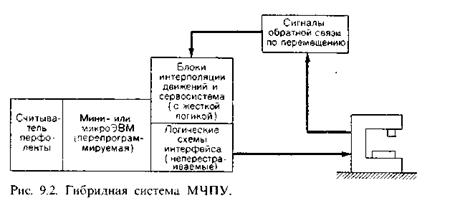
Figure 5 Hybrid CNC system
Two alternative configurations of MNC devices have been developed:
1. Hybrid MNC systems.
2. Direct MNC systems.
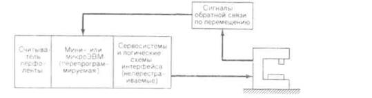
Rice. 6. System of direct numerical control (NCNC).
In the direct configuration of the system, the MNC computer is used to perform all the functions of numerical control. Only elements of the interface connecting the computer with the machine and with the operator's console are implemented in hardware. Interpolation, feedback on the position of the tool and all other functions are carried out by computer software. In accordance with this, a more powerful computer is required in a direct MNC system than in a hybrid one. The advantage of the direct MNC configuration is the added flexibility. Here it is possible to make changes to the interpolation programs, while the logic "soldered" into the hardware circuits of hybrid systems cannot be rebuilt. The scheme for constructing a direct MCPU system is shown in fig. 6.
Compensation for deviations in the processing of parts. The function is closely related to machine control. This provides for dynamic correction of machine movements to compensate for changes or errors that occur while the part is being machined.
Providing enhanced capabilities in programming and operation modes. The flexibility of software-configurable control devices has made it possible to provide many convenient options when programming the system and when processing parts.
Diagnostics. CNC machines are complex and expensive systems. Ideally, the diagnostic subsystem should perform several functions. First, it must be able to identify the cause of the downtime so that maintenance personnel can make repairs faster. Secondly, the diagnostic subsystem must be sensitive to signs that portend an approaching failure of one or another element. This will allow maintenance personnel to replace the defective element in a timely manner during scheduled maintenance, which will prevent an unexpected stop in production. The third possible function is related to the fact that MNC systems may contain a certain number of redundant elements from among those that are considered unreliable. If one of these elements fails, the diagnostic subsystem will automatically turn it off and use the same type element from the reserve.
Bibliography
1. Automated preparation of programs for CNC machines, (Handbook) / R.E. Safraghan, G.B. Evgenev, A.L. Deryabin and others; Under the general editorship. R.E. Safragana. - K .: Technique, 1986. - 191 p.
2. R.I. Gzhirov, P.P. Serebrenitsky. Programming processing on CNC machines. Handbook, - L .: Mashinostroenie, 1990. - 592 p.


How to understand: will the kitten be fluffy?
What kind of light alcohol can be drunk for pregnant women: the consequences of drinking
Why do the legs swell in the ankles and ankles of the feet in pregnant women: causes and methods of treatment
The wedding of Prince Harry and Meghan Markle: scandalous and secret details of the marriage (photo) The future marriage of Prince Harry year NTV
How to close white plums for the winter