Device classification
DESIGN OF TOOLING FOR SPARO PRODUCTION
Purpose of fixtures
Devices are a piece of technological equipment used to speed up and facilitate operations. machining, assembly and control.
The use of devices contributes to:
1) Improving the productivity and accuracy of processing, assembly and control.
2) Facilitate the work of workers.
3) Expansion of the technological capabilities of the equipment.
4) Improving labor safety.
5) Reducing the required qualification of workers.
6) No markup required.
Device classification
Devices are classified according to their purpose and degree of specialization.
According to the intended purpose, the devices are divided into 5 groups:
1) Machine tools. Are used for installation and fixing of the processed preparations. They make up 80 to 90% of the total fleet of devices. They are named after the type of machine.
2) Machine fixtures for fixing the working tool (auxiliary tool). Mandrels, adapter sleeves, cutting tool chucks, holders.
3) Assembly fixtures - for making connections of mating parts into assemblies and products.
a) For fastening base parts or assembly units (assemblies).
b) To ensure correct installation connected elements into products.
c) For preliminary deformation of mating elastic elements.
d) For pressing, riveting, flaring.
4) Control devices - for checking blanks and parts, as well as assembled machine components.
5) For gripping, moving and turning over workpieces and assembly units.
According to the degree of specialization, devices are divided into:
1) Universal
1.1) Universal non-adjustment (UBP) - used in single and serial production for installation and fixing of parts with various shapes and sizes. Universal chucks, vise, etc.
1.2) Universal setting (UNP) - used to secure workpieces of various configurations. Consist of 2 parts: universal and replaceable.
The universal part is the housing and the drive. The rest is interchangeable.
Universal chucks with interchangeable jaws, group fixtures. They are used in small-scale and medium-scale production for processing parts of various shapes.
2) Specialized
2.1) Specialized non-adjustment (SBP) - used to fix workpieces similar in design and technological features with the same base surfaces and requiring the same processing. Details: rollers, bushings, brackets.
2.2) Specialized setup (SNP) - used to secure workpieces of similar sizes. Consist of 2 parts: universal and replaceable. In them, you can adjust the installation elements for processing parts of different sizes. They are used in mass production for group processing of parts.
3) Special
3.1) Non-separable special devices (NSP). They are assembled from normalized parts to make specific mass-produced parts.
3.2) Collapsible fixtures. They use custom clamping and power units, which can be used many times in this plant.
3.3) Universal prefabricated devices (USP). Produce 3 series of different overall dimensions. The entire USP set consists of groups of parts:
Basic details;
Body parts;
guides;
Clamping parts;
fasteners;
Indestructible knots.
USP parts are made of steel 12KhN3A, HRC 62…64. USP service life is 15-20 years.
Types of fixtures.
In concept technological equipment includes various devices - mechanical devices used to secure workpieces during machining, assembly and control of various products. According to the classification, the devices are divided into the following types: 1. Machine tools- applied, for installation and fixing on machines of the processed preparations. 2. To install and secure the cutting tool.3. Assembly fixtures- for connecting mating parts into assembly units and assemblies. They are used for pre-assembly of elastic elements (springs), for making tight connections, etc.4.Control fixtures- used for intermediate and final control of the dimensions of parts. According to the level of specialization, devices are distinguished:
- universal- designed for processing various workpieces (vises, 3-jaw chucks (see Fig. 1), dividing tables and heads, etc.);
- specialized- for processing workpieces of the same type (various mechanisms with interchangeable devices - dividing device with a set of interchangeable collets);
- special- designed to perform one or more operations on a given part (overhead conductors - Fig. 2, etc.).
 Rice. 2.
In conditions of mass production, so-called universally reversible devices are also used. They consist of many normalized elements and can be quickly and repeatedly rearranged, as a result of which they can be used to perform various operations. This helps to reduce the time of manufacturing and implementation of technological equipment.
There are two main systems of universally reversible fixtures, universal-assembly (USP) - Fig. 3 and universal-adjustment (UNP).
System USP consists of a set of normalized parts, from which you can quickly, according to the principle of universal assembly and interchangeability, assemble various single-purpose devices. After using the device assembled according to the application, it is disassembled and the parts are returned to the warehouse; then new arrangements can be assembled from them. Thus, the USP system is universal only in relation to the manufacture of fixtures. The latter are obtained not universal, but special (single-purpose). The USP system includes a set of 25,000-30,000 parts and a number of normalized non-separable units. From this set, you can collect up to 300 adaptations at the same time.
The system of universal setting devices is based on the use of replaceable mounting, clamping and guiding elements fixed on the basis of a universal normalized device.
Among the normalized devices, on the basis of which the UNP is assembled, are machine vise with replaceable jaws, rocky conductors, pneumatic chucks with interchangeable jaws (Fig. 4), collet devices and others.
The use of UNP reduces costs and terms of technological preparation of production, increases its flexibility. When starting a new batch of workpieces, the fixtures are not removed from the machine, but only the replaceable elements are reinstalled. Replaceable parts and assemblies of the UNP are stored at the workplace near the machine. Their installation on the device is carried out by centering pins, pins or guide grooves without alignment and takes about 5 minutes. As a result, the time for organizing the workplace is reduced and the utilization rate of machine equipment in time increases.
The presence of a developed fleet of UNP at the operating plant facilitates the transition to a new production facility. At the same time, the preparation time for production can be reduced, since there is no need to design and manufacture numerous special equipment.
The use of devices provides:
- 1) increase in labor productivity due to reduced set-up and clamping times ( t in); due to the use of multi-place and multi-tool processing (by reducing t0);
- 2)Improve processing accuracy due to a more accurate installation of the workpiece and machine settings;
- 3) facilitating the working conditions of machine operators; expansion of technological capabilities of equipment.

The rocky conductor is a universally adjusted device. It is completed with interchangeable, normalized parts: jig plates 6, quick-change jig bushings, clamping elements 7 and positioning elements 1 and 2.
CLASSIFICATION OF DEVICES
DEVICE DESIGN METHOD.
INITIAL DATA
For the design of the device, the following initial data are required:
Blueprints technical requirements per item;
Operational sketch of a workpiece, operation or transition;
Reference literature, GOSTs, OSTs and factory normals;
The main dimensions of the machine and its characteristics.
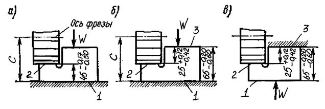
Figures 4.1-4.6 show, as an example, a technique for designing a fixture that serves to fix a workpiece on a milling machine. The processing of the workpiece consists in milling surface A, drilling four mounting holes, two of which are reamed.
The blank is based in cones along the hole. Set of bases: 1, 2, 3, 4 - double guide base; 5 and 6 - support bases.
The sequence of development of the design of the device
Rice. 4.1. Detail drawing.
Rice. 4.2. Scheme of basing the workpiece in the fixture, determining the points of application and the direction of the force closure.

Rice. 4.3. Drawing of the installation, guides and support elements of the device.
Rice. 4.4. Drawing of clamping, fixing, auxiliary elements of the device.

Rice. 4.5. Clamping drive. Drive selection is based on required workpiece clamping force and drive dimensions.

Rice. 4.6. The body of the fixture with devices for attaching it to the machine table.
Rigid center bars
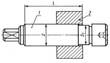
Rice. 5.11. Smooth conical mandrel (1 - mandrel; 2 - billet).
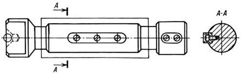
Rice. 5.12. Smooth mandrel with key.
Rice. 5.13. Cylindrical mandrel for pressing.
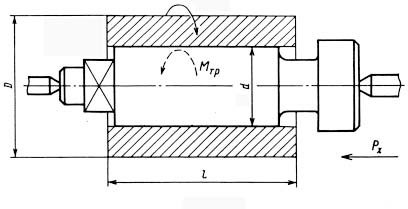
Conventions: Mrez - moment of cutting forces; Px - cutting resistance force; Мfr - moment of friction on the contact surface; d is the diameter of the mandrel; D is the diameter of the workpiece being processed; l is the length of the workpiece being processed.

Rice. 5.14. Tapered mandrel (1 - mandrel; 2 - billet).
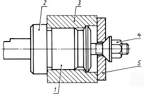
Rice. 5.15. Smooth center mandrel (1 - mandrel; 2 - flange; 3 - workpiece; 4 - nut; 5 - washer).
Rice. 5.16. The mandrel is cam spindle.
Symbols: Q - axial thrust force; D - landing diameter; d is the diameter of the cams;
d1 is the rod diameter; l is the length of the mandrel.
Rice. 5.17. Thin-walled mandrel with hydroplastic (1 - lever; 2 - plunger; 3 - hydroplastic; 4 - workpiece; 5 - expansion bar; 6 - thrust).
Legend: Q - force on the cylinder rod.
Rice. 5.18. Cantilever mandrel with belleville springs (1 - package of belleville springs; 2 - billet).
Symbols: R - radius of the processed surface of the workpiece; Q - axial force on the rod of a mechanized drive.
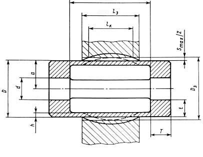
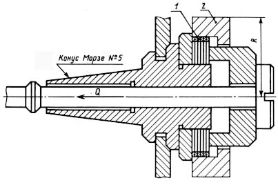
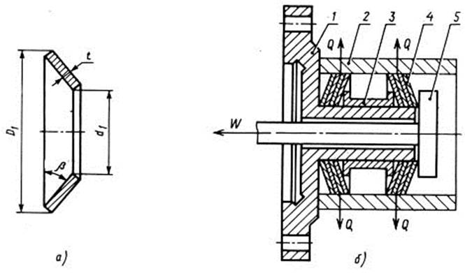
Rice. 5.19. Thin-walled sleeve for fastening workpieces.
Symbols: D - diameter of the mounting surface of the sleeve; h is the thickness of the thin-walled part of the sleeve; T is the length of the support bands; t is the thickness of the support bands; Smax - maximum gap between the sleeve and the workpiece; lk - length of the contact section of the sleeve; lz is the length of the workpiece; Dz - diameter of the base surface of the workpiece; d is the diameter of the hole in the support belts of the bushing.
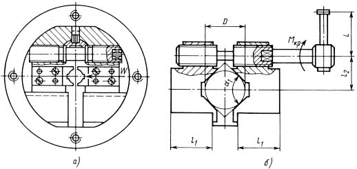
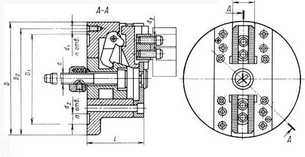
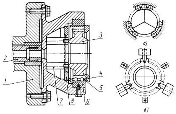
Rice. 5.20. Universal two-jaw chuck. a - general view of the cartridge; b - diagram of the mechanism of the cartridge.
Legend: W - clamping force; Mkr - the required torque on the key; L - handle length; D - diameter of the clamped part; l1 - length of the guide part of the cam; l2 - distance between the axis of the clamping screw and the axis of the prism; a1 - cam prism angle.
![]()
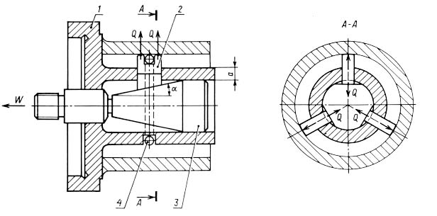
Rice. 5.21. Three-jaw self-centering chuck (1 - body; 2 - disk; 3 - rail; 4 - screw; 5 - overhead cam; 6 - bevel gear; 7 - cover).
Symbols: H - the width of the cartridge; D is the diameter of the cartridge body.
Rice. 5.22. Scheme wedge-plunger lathe chuck(1 - body; 2 - plunger; 3 - wedge; 4 - ball).
Symbols: Q - clamping force by one plunger; W is the thrust force of the drive; a - the angle of inclination of the wedge cone; a is the thickness of the casing sleeve.
Rice. 5.23. Universal three-jaw chuck with a mechanized drive (1 - housing; 2 - cam; 3 - cracker; 4 - screw; 5 - replaceable cam; 6, 7 - bushings; 8 - thrust; a - groove in the sleeve 6; b - cam protrusion 2).
Symbols: Q - axial force on the rod of a mechanized drive; W - chuck jaw clamp.
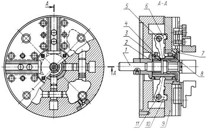
Rice. 5.24. Universal four-jaw chuck (1 - thrust; 2, 3, 4, 7 - bushings; 5 - lever axis; 6, 10 - levers; 8 - floating ball; 9 - cam; 11 - lever axis). Used for mounting and clamping non-circular parts.
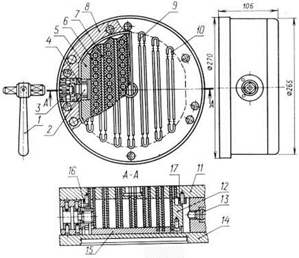
Rice. 5.25. Cartridge with a permanent magnet (1 - key; 2 - screw; 3 - sleeve; 4 - nut; 5, 7, 12 - plates; 6 - permanent magnet; 8 - chuck body; 9, 10 - inserts; 11 - top plate; 13 - plug; 14 - plate; 15 - intermediate plate; 16, 17 - stops).
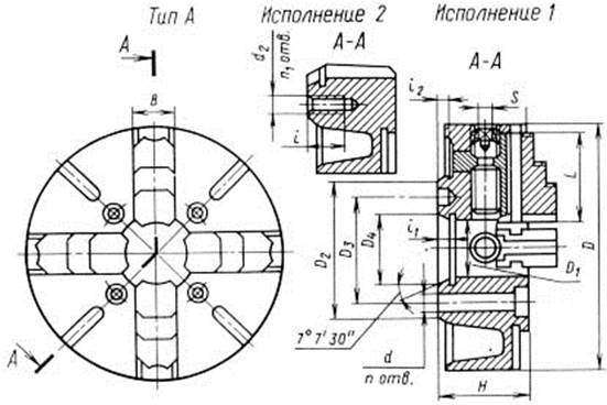
Rice. 5.26. Four-jaw chuck with independent jaw movement.
There are two types of ammo:
Type A - for mounting on the flanged end of the spindle;
Type B - for mounting on the threaded end of the spindle. The figure shows a chuck for mounting on the flanged end of the spindle: Execution 1 - with mounting on the flanged end of the spindle; Execution 2 - with fastening on the flanged end of the spindle under the washer.
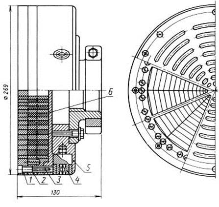
Rice. 5.27. Magnetic chuck PTM-250 (1 - adapter plate; 2 - movable block; 4 - conical wheel; 5 - housing; 6 - driven wheel).
Rice. 5.28. Cartridge self-centering lever-wedge two-jaw.
Cartridge dimensions, mm
Rice. 5.29. Clamping device for processing a conical wheel-disk (1 - retainer; 2 - outer disc-shaped membrane; 3 - rod; 4 - inner disc-shaped membrane; 5 - machined wheel; 6 - support wheel; 7 - mandrel; 8 - key; 9 - Belleville spring; 10 - sleeve). When fixing the conical wheel-disk, the rod 3 moves in the direction of the clamping force P.
Rice. 5.30. Round electromagnetic chuck for a lathe for fastening thin flat parts (1 - metal casing; 2 - textolite shield; 3 - labyrinth ring; 4 - housing; 5 - nut; 6 - coil; 7 - fixed nut; 8 - contact rings; 9 - clamp; 10 - hairpin; 11 - brush holders with brushes).

Rice. 5.31. Devices for fastening gears during their processing:
a - for processing bevel gears (1 - spindle; 2 - stop);
b - with rigid centering (1 - washer; 2 - key; 3 - gear; 4 - flange; 5 - thrust);
v - jig for a wheel with a hub (1 - gear; 2 - rod; 3 - collet; 4 - screw);
g - clamping device for fastening the differential satellite (1 - template; 2 - differential satellite; 3 - collet; 4 - rod).
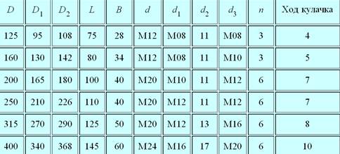
Rice. 5.32. Diaphragm cartridge (1 - membrane; 2 - rod; 3 - gear; 4 - separator; 5 - roller; 6 - cam; 7 - finger; 8 - bar).
a - layout of the rollers;
b - diagram of a cartridge with three wedge fingers.
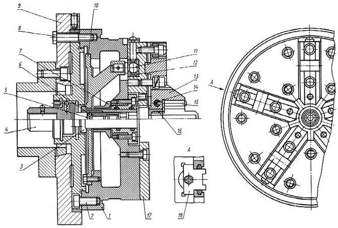
Rice. 5.33. Membrane chuck for mounting and clamping cylindrical gears (1 - chuck body; 2, 5, 8 - screws; 3, 4, 7 - bushings; 6 - ball; 9 - faceplate; 10 - membrane (disk); 11 - spherical support ; 12 - spherical washer; 13 - replaceable cam; 14 - rubber rod; 15 - roller;
16 - ring; 17 - sector; 18 - block).
The diaphragm chuck has five jaws for high centering accuracy when grinding gear teeth.

Rice. 5.34. Diaphragm cartridge (1 - membrane cartridge body; 2 - thrust; 3 - membrane; 4 - chuck cam; 5 - workpiece): a - the part is clamped in the membrane cartridge; b - cartridge in the expanded state.
Legend: W - radial force on one jaw of the diaphragm cartridge; Q - force on the shield; d is the diameter of the part; d is the distance from the membrane to the middle of the cam.
Rice. 5.35. Cartridge with annular membranes: a - annular membrane; b - scheme of the cartridge mechanism with annular membranes (1 - body; 2 - workpiece; 3 - sleeve; 4 - package of membranes; 5 - rod).
Symbols: W - traction force; Q is the force acting on the workpiece; b = 9...12° - the angle of inclination of the membrane in the deformed state; D1- outside diameter membranes; d1 is the diameter of the hole in the membrane; t is the thickness of the membrane.
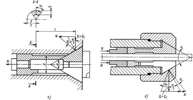
Rice. 5.36. Collet chucks:
a - with a retractable collet;
b - with a retractable collet.
They are used for clamping calibrated bars of various profiles processed on turret machines and bar machines.
Symbols: N - axial force; Q is the radial force acting on the part; Q1 - pre-compression force of the collet petals; a = 30...40° - angle at the top of the collet cone; j = 6...8° - angle of friction; l - the length of the petal of the collet from the place it touched to the middle of the cone of the collet; D is the outer diameter of the petals of the collet; s is the thickness of the bending tab of the collet.
Multi-spindle heads
Multi-spindle heads provide simultaneous operation of several similar or dissimilar tools (drills, countersinks, reamers, taps) and can be special and universal. Special heads are used to machine parts with a certain arrangement of holes, so their spindles cannot change their position. Such heads are used in large-scale and mass production. Universal heads have the ability to change the position of the spindles. One head can process various parts. They are used in mass production. The head spindles are driven from the machine spindle by means of gears.
Rice. 6.14. Multi-spindle head with cantilever gears (1 - spindle; 2, 3 - gears; 4 - roller; 5 - plug).
Designed for simultaneous processing of four holes. The drive shaft 4 is connected by segment keys with the drive gear 3, which is engaged simultaneously with all gears 2 of the working spindles 1.
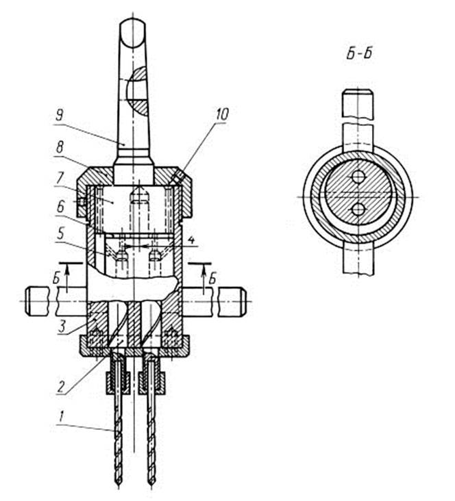
Rice. 6.15. Multi-spindle head without gears (1 - drill; 2 - spindle; 3 - housing;
4 - rod; 5 - detail; 6 - bronze washer; 7 - flange; 8 - cover; 9 - shank; 10 - cork).
Designed for processing holes with a diameter of 5.5 mm, the axes of which are at a distance of l = 15 mm. The conical shank 9 for fastening the head in the machine spindle is made as one piece with a cylindrical flange 7 having a hole with an axis offset of 4 mm from the axis of the shank. Part 5 is placed in the flange, the holes of which include the shanks of the working spindles 2 located with an eccentricity of 4 mm. When the machine spindle rotates, part 5 performs a reciprocating motion, in which its axis and the axes of the shanks of the spindles 2 have the same speed as the spindle machine. To prevent rotation of the body 3 of the head, the rods 4 must come into contact with the fixed part of the machine before starting work.
Rice. 6.16. Multi-spindle head with internal gears (1 - sleeve; 2 - gear; 3 - support; 4 - balls; 5, 6 - thrust bearings; 7 - plain bearing; 8 - roller; 9 - drill; 10 - collet; 11 - screw).
Designed for drilling small diameter holes. The drive shaft 8 is made as one piece with the drive gear and is supported by a plain bearing 7 and a thrust bearing 6. A common thrust bearing 5 is used for all spindles.
To reduce friction between the ring of this bearing and the spindles in the undercuts of the gears 2, balls 4 are placed on hardened bearings 3. Drills 9 are fastened with collets 10 with nuts 11. The side platform P on the drill shank protects the drill from turning.
Rice. 6.17. Multi-spindle head for machining holes located in a straight line: a - drawing of the head assembly (1 - body; 2 - bracket; 3 - intermediate gear; 4 - gear; 5 - spindle); b - spindle block.
The head allows you to change the distance l between two adjacent spindles within 62...100 mm. The central spindle 5 does not change its position and is driven by a gear wheel 4. The remaining spindles rotate by means of intermediate gear wheels 3 and can change their position relative to the central spindle 5. For this purpose, the axes of the wheels 3 are placed in brackets 2, which can be rotated relative to the housings 1 spindles, which allows you to bring the spindles together or move them apart.
Rice. 6.18. Multi-spindle head with a two-tier arrangement of gears (1 - spindle; 2, 8 - intermediate gears; 3 - gear; 4, 9 - drive gears; 5 - drive roller; 6 - stud; 7 - sleeve of the machine headstock; 10 - spindle; 11 - thrust bearing; 12 - ball bearing).
It is intended for processing of six openings located on a circle. In the lower tier there are two intermediate gears 2, each of which drives two spindles 10 through the drive gears 9. Two spindles 1 are driven by the drive gears 4 through the intermediate gears 8 located in the upper tier. There are no intermediate gears on the other two spindles. The gear wheel 3 of the drive shaft 5 is twice as wide, as it drives the wheels placed in two tiers.
Basic parameters of the multi-spindle head
![]()

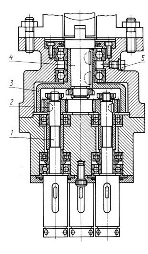
Rice. 6.19. Three-spindle drilling head with single-tiered gears
(1 - stud; 2, 3, 6 - gears; 4, 5 - spindles; 7 - sleeve).
The head is attached to the machine with studs 1. The head is connected to the machine spindle by a sleeve 7 fixed on the shank of the spindle 5, on which the gear wheel 3 is installed. From the gear wheel 3, the rotation is transmitted to the wheels 2 and 6 of the side spindles 4 through the intermediate gear wheels.
AUTOMATIC LINES
STANKOV
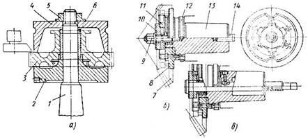
Rice. 11.1. Devices for gear processing: a - a device for a gear shaping machine (1 - mandrel; 2 - support washer; 3 - gear being machined; 4 - clamping washer; 5 - nut; 6 - adapter sleeve for installing wheels with different hole diameters); b - devices for gear cutting (gear milling) of bevel gears (7 - workpiece; 8 - replaceable flange; 9 - nut; 10, 11 - washers for clamping; 12 - nut for removing the device; 13 - mandrel; 14 - rod for tightening mandrels); c - a mechanized device for gear cutting of bevel wheels, the clamp is made with the help of traction.
Rice. 11.2. Devices for hobbing machines: a - device for simultaneous multi-place processing (1 - annular diaphragm; 2 - holder, 3 - rod; 4 - workpiece; 5 - removable washer, 6 - mandrel; 7 - thrust; 8 - spring; 9 - diaphragm cavity) b - fixture with a replaceable cassette (10 - bolts for clamping parts; 11 - mandrel; 12 - bushing; 13 - threaded rod for fastening the cassette; 14 - centering rings; 15 - gears; 16 - coupling for easy removal of the cassette; 17 - body, 18 - permanent base fixed on the machine; 19 - finger).
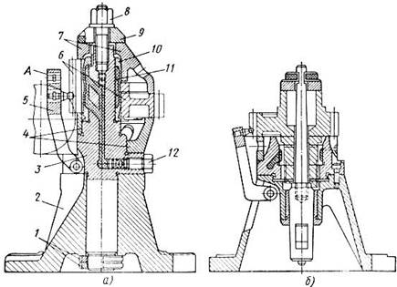
Rice. 11.3. Devices for fine gearing: a - for the wheel (1 - nuts; 2 - body; 3 - mandrel with a tapered shank; 4 - adapters; 5 - hinged lock; 6 - wheel; 7 - adapter; 8 - nut for clamping; 9 - washer; 10 - thin-walled shell; 11 - hydroplastic; 12 - pressure screw); b - for the gear shaft.
CLASSIFICATION OF DEVICES
Classification of devices is carried out according to the following criteria:
1. According to the intended purpose, the devices are divided into five groups:
Machine fixtures for mounting and fixing workpieces on machine tools. Depending on the type of processing, turning, milling, drilling, boring, grinding and other devices are distinguished;
Devices for fastening the cutting tool. They are characterized by a large number of normalized parts and structures, which is explained by the normalization and standardization of the cutting tools themselves;
Assembly fixtures are used when performing assembly operations that require high assembly accuracy and great effort;
Control and measuring devices are used to control workpieces, intermediate and final control, as well as to check assembled units and machines. Control devices are used to install a measuring tool;
Devices for gripping, moving and turning over workpieces, as well as individual parts and assemblies during assembly.
2. According to the degree of specialization, devices are divided into universal, specialized and special.
Universal fixtures (UP) are used to expand the technological capabilities of metal-cutting machines. These include universal, rotary, dividing tables; self-centering chucks.
Universal non-adjustment devices (UBD) are used for locating and fixing the same type of blanks in the conditions of single-piece and small-scale production. This type includes universal chucks with one-piece jaws, universal milling and metalwork vise.
Universal adjustment devices (UNP) are used for basing and fixing workpieces in a multi-product production. These include universal chucks with interchangeable jaws, universal vices, rock jigs.
Specialized non-adjustment devices (SBP) are used for locating and fixing workpieces that are similar in design features and require the same processing. Such devices include devices for processing stepped rollers, bushings, flanges, disks, body parts, etc.
Specialized adjustment devices (SNP) are used for locating and fixing workpieces that are similar in design and technological features and require the same type of operations and special adjustments to be processed.
Universal prefabricated devices (U SP) are used for basing and fixing a specific part. A special fixture is assembled from the USP kit, which is then disassembled, and USP elements are repeatedly used to assemble other fixtures.
Special devices (SP) are used to perform a specific operation and when processing a specific part. Such devices are called single-purpose. They are used in large-scale and mass production.
3. By functional purpose fixture elements are divided into mounting, clamping, power drives, elements for guiding the cutting tool, auxiliary mechanisms, as well as auxiliary and fasteners (handles, crackers, dowels). All these elements are connected by body parts.
4. According to the degree of mechanization and automation, devices are divided into manual, mechanized, semi-automatic and automatic.
1.1. Service purpose of devices
The intensification of production in mechanical engineering is inextricably linked with the technical re-equipment and modernization of the means of production based on the application of the latest achievements of science and technology. Technical re-equipment, preparation for the production of new types of engineering products and modernization of means of production inevitably include the processes of designing technological equipment and their manufacture.
Approximately 50% of the total amount of technological equipment is machine tools. The use of machine tools allows: 1) to implement a theoretical basing scheme and fix the workpiece while maintaining its rigidity during processing;
2) consistently ensure the high quality of workpieces with a minimum dependence of quality on the qualifications of the worker;
3) increase productivity and ease the working conditions of the worker as a result of the mechanization of devices;
4) expand the technological capabilities of the equipment used.
The service purpose of devices is understood as a clearly formulated technological problem, for the solution of which it is created.
Among the tasks, the solution of which is achieved by the use of devices, three main ones can be distinguished:
I. Installation of workpieces on machines without alignment. The use of fixtures for setting workpieces eliminates the expensive and time-consuming marking operation, eliminates the alignment of the workpiece on the machine, provides the ability to automatically obtain dimensional accuracy, and therefore increases the accuracy of processing by eliminating errors associated with marking and alignment.
2. Increasing labor productivity. High labor productivity equally depends on both high-performance equipment and high-performance fixture. To increase labor productivity means to reduce the rate of piece time for an operation. The norm of piece-calculation time is determined by the formula:
T pcs-k \u003d T about + T in + T tech.ob + T org.ob + T lane +
The main time -T about can be reduced by: a) increasing the number of simultaneously working tools; b) simultaneous processing of several workpieces (for this, multi-place devices or devices for setting workpieces in packages are designed); c) increasing the cutting conditions (designing devices that increase the rigidity of the technological system, allows you to increase the cutting conditions and apply a lot of tooling).
Auxiliary time - T in can be reduced by reducing the time for setting and fixing workpieces or by combining auxiliary time with the main one.
When using fixtures, the worker may not check the position of the workpiece during installation. To reduce the clamping time of the workpiece, high-speed manual, mechanized, automated and multiple clamping devices, rotary devices, automatic loading devices, ejectors, etc. are designed.
Time Maintenance workplace -T maintenance is reduced using quick-change chucks, multi-cutting holders, in which adjustment is carried out outside the machine on special devices, templates for setting tools to size, etc.
Organizational maintenance time - Tlimit can be reduced by creating windows and trays for chip removal, devices for automatic chip removal and transportation, etc.
The time of regulated breaks T lane is reduced through the use of devices that facilitate the work of workers.
The preparatory-final time T p.z is reduced by the same measures as T org.ob, but also by creating fixtures that ensure their accurate and quick installation on the machine without alignment and allow quick changeover of fixtures for processing different workpieces.
The task of the technologist to ensure an increase in labor productivity is to analyze the norm of time to reduce its components.
3. Expanding the technological capabilities of the equipment. Plants of single and small-scale production are equipped mainly with universal metal-cutting machines. Each machine is designed to perform a specific job with a given accuracy.
For such machines, special devices are used that expand the technological capabilities of the equipment, for example, with the help of special devices, grinding, broaching and milling can be performed on lathe, boring and slotting - on a milling machine, processing of precise holes on drilling machine etc.
When developing fixtures, there are ample opportunities for displaying creative initiative to create designs that provide the greatest efficiency and profitability of production, to reduce the cost of fixtures and reduce the time of their manufacture. Fixtures must be comfortable and safe to use, fast, rigid enough to ensure the specified machining accuracy, convenient for quick installation on the machine, which is especially important when changing fixtures in serial production, simple and cheap to manufacture, accessible for repair and replacement of worn parts. .
1.2 Classification of fixtures
Technological equipment is divided into three categories:
By intended purpose Technological equipment can be divided into five main groups.
1. Machine fixtures used to install and secure workpieces in accordance with the conditions of the technological process. These devices are divided into drilling, milling, boring, turning, broaching, slotting, etc. The group of machine tools also includes special-purpose devices (for bending, straightening, etc.).
2. Devices for fixing the working tool. They act as a link between the tool and the machine, while the first group of devices connects the workpiece with the machine. With the help of devices of the first and second groups, the technological system is adjusted.
This group of devices is also called an auxiliary tool, characterized by a large number of normalized and standard devices due to the wide standardization and normalization of tools.
3.Assembly fixtures used to perform, connect mating parts into assemblies and products.
4. Control devices used to check the product, during the intermediate and final control of parts during processing, as well as to check the assembled machine components.
5. Devices for gripping, moving and turning over processed workpieces and assemblies. These devices are used for heavy objects that cannot be moved manually. or difficult. V automated production This group of devices is used for all types of workpieces.
By degree of specialization devices are divided into three groups:
1. Universal fixtures used in individual and small-scale production. They are used for fixing and processing workpieces of a wide range and various sizes. Universal fixtures are divided into non-adjustable and adjustment.
2. Adjustable or specialized (reversible) devices, i.e. reusable devices. Used in small and medium batch production. Specialized (group) fixtures have limited limits of versatility and are used in the processing of workpieces that have a structural and technological commonality, included in one classified unit, therefore, having the same nature of the location of the surfaces that serve as installation bases in the fixture.
Specialized devices combine the positive qualities of universal designs (the ability to reuse when changing the production object) and special designs (speed of action, processing accuracy, simplicity of design, high productivity).
In the transition from the processing of one workpiece to the processing of another, a specialized fixture, as well as a universal adjustment one, is equipped with simple interchangeable adjustments.
Specialized devices include:
1) Universally prefabricated (USP) and collapsible (PSA) fixtures assembled from a set of normalized parts and assemblies;
2) Universal setting devices (UNP) - with interchangeable settings, allowing you to process workpieces of various names;
3) Group reconfigurable fixtures with interchangeable adjustments, giving the possibility of processing a certain group of workpieces.
3. Special devices designed to perform certain technological operations and are reconfigurable devices for a single purpose. They are mainly used in large-scale and mass production.
According to the degree of mechanization and automation of the device are divided into 4 groups:
1. With manual drive.
2. Mechanized drive.
3. Semi-automatic.
4. Automatic.
Devices are subject to the following basic requirements:
a) ensuring the specified accuracy of processing;
b) Simplicity of design and lowest manufacturing cost;
c) the rationality of the design and ensuring safety;
d) convenience and ease of installation of the workpiece on the machine;
e) convenience of work;
f) ease of repair and availability of replacement of worn parts.
Universal adjustment devices (UNP) consist of two parts - universal and adjustment. The universal part includes the body of the fixture, the drive and bases for installing interchangeable adjustments, and the setting part has bases for installing the workpiece and elements for guiding or coordinating the tool.
The universal part of the fixture, as a rule, has two or more kinematic chains that provide simple or combined clamping of the part and adjusting the position of the elements on which the changeable adjustments are installed.
As mentioned above, the design of the housing and drive does not depend on the geometric shape of the parts, but on its overall dimensions, therefore the universal part is a permanent normalized part of the UNP, designed to process parts of the entire classified subdivision.
An important condition for the successful application of the CNP is to ensure fast and accurate installation of interchangeable adjustments. The effectiveness of universal adjustment devices largely depends on this. Therefore, when designing the universal part of the UNP, special attention is paid to the convenience and ease of installation of interchangeable adjustments when minimal cost auxiliary time (no more than 3 minutes).
Interchangeable adjustments are made depending on the shape and dimensions of the mounting base surfaces of the workpieces. On the one hand, they have bases in accordance with the design features of each part separately, and on the other hand, interchangeable normalized bases that allow them to be installed in the same universal part of the fixture.
Thus, the interchangeable setup is, as it were, a technological appendage of the part, unifies the mounting bases and allows the workpiece to be processed in a high-performance fixture.
1.3. Basic principles for selecting fixtures for single, serial and mass production.
The rules for selecting tooling establishes the procedure for selecting systems and tooling designs not only in accordance with their operational characteristics and the specifics of the production of products, but also on the basis of ensuring the intensification of its operation.
A modern machine-building enterprise is characterized by various types of production, seriality, dimensions and shape of products, which determines the use within the same enterprise. various systems fixtures. The complex task of choosing systems of machine tools is to determine the volumes of devices of various systems that equip the operations, which will provide the maximum economic efficiency in total both in the field of pre-production and in the field of product manufacturing.
Such a task, due to its large dimension, can only be solved using modern information retrieval systems.
To solve this problem, you can be guided by some concepts and recommendations from the field of standardization and unification.
Comprehensive standardization of joint venture - a process ordered by the rules and regulations of the State Standardization System that ensures the optimal level of technological readiness for the production of products as a result of the development, assembly and use of a permanent fleet of standard and unified joint ventures of various systems.
Unification of the joint venture - part of the complex standardization of the joint venture, which consists in bringing to uniformity based on a rational reduction in the number, types, main parameters of the joint venture, their assembly units, parts, structural elements, grades of materials, coatings, accuracy standards, etc.
SP system - a set of joint ventures that are created on the basis of uniform rules in order to ensure the unity of their implementation and use in certain organizational conditions of the technological process of manufacturing various products by cutting. SP systems are used based on the application of the rules and regulations of the ESTPP to achieve high technological readiness of industrial enterprises for the production of various products in accordance with the specified technical, economic and planned indicators.
Universal non-adjustment devices (UBP) are non-separable joint ventures of multiple use, which are operated without modification. Effective in the conditions of a single small-scale production of the same type of parts. Examples are centers, universal chucks, stands, etc.
Universal setting devices (UNP) are collapsible joint ventures of multiple use. The layout of the UNP consists of a base part, universal in terms of basing schemes and structural forms of the workpieces to be installed, and a replaceable setup. These types of devices are effective in the conditions of single and serial multi-product production. Examples are universal setting vises, etc.
Specialized adjustment devices (SNP) are collapsible joint ventures of multiple use. The layout of the SNP consists of a base part, specialized according to the schemes for basing typical groups of processed workpieces, and shift adjustment. These types of devices are effective in mass production.
Universal prefabricated fixtures (USP) are collapsible joint ventures of multiple use. The USP layout is assembled from high-precision standard universal parts and assembly units and does not require additional machining. Effective in the conditions of single and small-scale production.
Collapsible fixtures (PSA) are collapsible joint ventures of multiple use. The layout of the PSA is assembled from standard parts and assembly units with their possible additional processing. Effective in the conditions of serial and large-scale production of products that are in the stage of continuous improvement, or products with a manufacturing period of up to one and a half years.
Irreversible Special Attachments (NSPs) are non-separable joint ventures of single use. Standard parts and assembly units are used in NSP designs general use. Such types of devices are effective in conditions of large-scale and mass production.
In the general case, the choice of a particular type of fixture should be accompanied by appropriate economic calculations.
The choice of one or another type of device must be justified by the economic feasibility of its assembly, manufacture and operation. Profitability calculations usually compare various design options devices for performing the same technological operation. If we assume that the costs of the cutting tool, depreciation of the machine and electricity are the same, then the elements of the cost of processing, depending on the design of the device, for the compared options a and b:
C a and C b - the cost of manufacturing or assembling the device according to option a and b , rub.; L a and L b - piece wages when using these devices, rub.; z- shop overheads for wages, %; q - costs associated with the operation of devices,%; i is the depreciation period of the device, years; n is the annual program for the production of parts, pcs; S a and S b are the costs of designing and debugging devices according to options a and b, rub; n | - the number of workpieces processed in fixtures for the period of development of manufactured products.
Design and debugging costs are attributed to the first samples of a new product or distributed to the cost of the product during a certain production time. A comparison of the economic efficiency of devices according to options a and b for a steady production period, when the costs of designing and debugging are repaid, can be made using the above formulas, assuming S" a = S" b = 0.
The value of the program for the production of parts, in which both compared options are economically equivalent, we find by solving equations (1) and (2) together with respect to n:
If the specified program is greater than the value calculated by formula (3) P, it is more profitable to use a more complex device, and vice versa.
For calculation P need to know the values S a and S b . Their exact values can be determined on the basis of calculations after the preparation of working drawings and the development of technological processes for the manufacture of fixtures. However, this method is complicated and time-consuming, while the task of designing a fixture must be completed in a short time. Therefore, simpler, approximate methods for determining the cost of manufacturing devices are used. For approximate calculations, you can use the approximate formula
S= sk,
where S is the cost of manufacturing the device, rub.; K- the number of parts in the fixture; C is a constant, depending on the complexity of the device. For simple fixtures WITH= 1.5, for fixtures of medium complexity C = 3.0, and for complex C = 4,0.
the value i take equal to the period during which the designed or selected device will be used to produce a given product. If, for example, these parts are produced within two years, then i also taken equal to two years. If the manufactured products are stable and the timing of the termination of its production is unknown, then it is recommended to take one year for simple fixtures, two to three years for medium complexity fixtures, and four to five years for complex fixtures. The value of q is recommended to be taken equal to 20% To determine L you need to know the piece time for this operation tpcs, and the minute wage of the worker With:
For the compared options, these values are different. When using a more advanced device t pcs, and With are reduced as a result of a reduction in the main and auxiliary time, as well as facilitating working conditions and simplifying the manipulations performed
The use of devices often causes a change in the technological process due to the elimination or modification of individual operations. In this case, it is possible to compare the cost of machining the workpiece, depending on the tooling, not by individual operations, but by processes:
where indices 1 and 2 refer to the compared process variants.
If different equipment is used in the compared options (for example, a horizontal boring machine is replaced by a vertical drilling machine), then taking into account the additional cost of 1 min of machine operation with st, we get
Let us now consider the cost of processing, if this technological operation is performed on a reconfigurable universal fixture equipped with a changeable setup:
where Sy- the cost of a universal device; S sn- the cost of manufacturing a changeable adjustment; i y- number of years of depreciation of the universal device; i sn- number of years of depreciation of changeable adjustment; S sn- expenses for the design and debugging of shift adjustment.
The above formula can be used to compare profitability various options reconfigurable fixtures or special and reconfigurable fixtures.
Example. Compare the economic feasibility of using a machine tool for two options: for the first option L 1 \u003d 0.020r, S 1 \u003d 150r .; for the second option L 2 \u003d 0.028r, S 2 \u003d 100r .; z=250%; q=20%; i=2. Annual production program of products 10 thousand pieces.
Solution. Using formula (3), we find the value of the program at which both options are economically justified:
Since the given program is larger than the program calculated by formula (3), it is more profitable to use a more complex device (option 1).
1.4. The main structural elements of devices.
With all the huge variety of machine tools, it is always possible to single out parts or mechanisms that perform the same or similar functions, although they can differ significantly in design. As a result, the concept fixture element .
Under fixture element refers to one part, a group of parts or a mechanism designed to perform a specific function (to achieve a specific goal).
In machine tools, it is customary to distinguish the following main elements:
installation;
clamping;
installation-clamping (self-centering);
guides;
dividing devices;
body elements;
power drives;
elements for basing and fixing fixtures on machines;
Mounting.
Installation elements(it is more correct to call them elements for basing the workpiece) fixtures are parts and mechanisms of fixtures that provide the required position of the workpiece to be processed in the selected coordinate system (relative to the machine coordinate system).
MINISTRY OF EDUCATION AND SCIENCE OF UKRAINE
KHARKOV STATE ACADEMY
URBAN SERVICES
FUNDAMENTALS OF DESIGN AND OPERATION OF TECHNOLOGICAL EQUIPMENT OF GET
(Lecture notes for 5th year students
specialty 7.092.202 "Electric transport")
Kharkov - 2003
Basics of design and operation technological equipment GET: Lecture notes for 5th year students of the specialty 7.092.202. "Electric Transport". Comp. - Movchan N.M., Babicheva O.F., Zakudai S.A. - Kharkov: KhGAGH, 2003. - 68 p.
Compiled by: N.M. Movchan, O.F. Babicheva, S.A. Zakudai
Introduction…………………………………………………………………….…….....4
1 GENERAL INFORMATION ABOUT DEVICES………………………….…....5
1.1 Purpose of devices…………………………………..……………...5
1.2 The role of technological equipment………………………………..……………..7
1.3 Classification of fixtures……………………………..……………….7
1.4 Design of technological equipment ............................................................................... 10
2 BASE AND BASE SURFACES………………………….…..13
2.1 Installation of workpieces in fixtures…………………………………...13
2.2 Calculation of actual basing errors during installation
parts in the fixture with a flat surface…………………….…..17
2.3 Calculation of fixtures for accuracy……………………………………….…..18
2.4 Rules for choosing bases……………………………………………………….….20
3 GENERAL INFORMATION ABOUT DEVICES.
TYPES OF DEVICES…………………………………………………...21
4 MAIN ELEMENTS OF DEVICES……………….…………...24
4.1 Installation elements of fixtures………………………….………24
4.1.1 Basic rules for installing workpieces……………………………….24
4.1.2 Types of installation elements of fixtures……………...……...26
4.2 Clamping elements of fixtures……………………………….……...34
4.2.1 Purpose of clamping elements……………………………………...34
4.2.2 Types of clamping elements……………………………………………..35
4.4 Dividing and turning elements of fixtures…………………...46
4.5 Tool housings………………………………………………….……48
4.6 Mechanized drives of devices…………………………….….50
4.6.1 Purpose of the motorized drive………………………….…..50
4.6.2 Pneumatic actuators………………………………………….…...51
4.6.3 Pneumohydraulic and hydraulic drives…………….……55
4.7 Universal assembly and adjustment devices……………….…..59
5 BASICS OF DEVICE DESIGN………….……..……63
5.1 Design of machine tools
using CAD ……………………………………………..……………66
INTRODUCTION
The main group of technological equipment is made up of fixtures for mechanical assembly production. Devices in mechanical engineering are called auxiliary devices for technological equipment used in processing, assembly and control operations.
The use of devices allows you to: eliminate the marking of workpieces before processing, increase its accuracy, increase labor productivity in operations, reduce product costs, facilitate working conditions and ensure its safety, expand the technological capabilities of equipment, organize multi-machine maintenance, apply technically sound time standards, reduce the number of workers required for production.
The frequent change of production facilities, associated with an increase in the pace of technological progress in the era of the scientific and technological revolution, requires technological science and practice to create structures and systems of devices, methods for their calculation, design and manufacture, ensuring a reduction in production preparation time. In mass production, it is necessary to use specialized quick-adjustable and reversible fixture systems. In small-scale and single-piece production, the system of universally prefabricated (USP) fixtures is increasingly being used.
The new requirements for fixtures are determined by the expansion of the CNC machine tool fleet, the changeover of which for processing a new workpiece comes down to changing the program (which takes very little time) and to replacing or readjusting the device for locating and fixing the workpiece (which should also take little time) .
The study of the regularities of the influence of the device on the accuracy and productivity of the operations performed will allow us to design devices that intensify production and increase its accuracy. The work on the unification and standardization of fixture elements creates the basis for the automated design of fixtures using electronic computers and automatic machines for graphic representation. This speeds up the technological preparation of production.
1 GENERAL INFORMATION ABOUT DEVICES
1.1 Purpose of fixtures
Among the tasks, the solution of which is achieved by the use of devices, three main ones can be distinguished.
1. Installation of workpieces on machines without alignment. The use of fixtures for setting workpieces eliminates the costly and time-consuming marking operation, eliminates the alignment of the workpiece on the machine, provides the ability to automatically obtain dimensional accuracy, and therefore increases the accuracy of processing by eliminating errors associated with marking and alignment.
2. Increasing labor productivity. Low labor intensity (high productivity) equally depends on both high-performance equipment and high-performance fixture. To increase labor productivity means to reduce the rate of piece time for an operation. The norm of piece-calculation time is determined by the formula:
The main time can be reduced in several ways:
1) an increase in the number of simultaneously working tools (when several tools work simultaneously, the operation from a multi-transition one and the time for processing a part is sharply reduced), for this purpose, multi-spindle drilling and milling heads, multi-tool holders for turret machines for several tools, etc. are designed;
2) simultaneous processing of several parts, for this multi-place devices and devices for installing parts in packages are designed;
3) an increase in cutting conditions. The design of devices that increase the rigidity of the AIDS technological system makes it possible to increase cutting conditions and apply multi-tool processing.
Non-productive time can be reduced by reducing the set-up and fixing time, or by combining non-productive and main time. When using fixtures, the worker may not check the position of the parts during installation. To reduce the fixing time of a part, designers design high-speed, manual, mechanized, automated and multiple devices, turning devices, automatic loading devices, ejectors, etc. be performed while the machine is running, so the time spent on these techniques is combined with the main time.
Therefore, the operating time can be reduced by using devices that increase the degree of concentration of machining operations. Devices expand the possibility of intensifying technological processes using parallel and parallel-sequential surface treatment schemes.
Workplace maintenance time is reduced by using quick-change chucks, multi-cutter holders, in which adjustment is carried out outside the machine on special devices, templates for setting tools to size, etc.
The time of organized maintenance can be reduced by creating windows and trays for chip removal in fixtures, devices for automatic chip cleaning and transportation, etc.
The time of regulated breaks is reduced through the use of devices that facilitate the work of workers.
The preparatory and final time is reduced due to the creation of fixtures: providing accurate and quick installation on the machine without alignment; allowing quick readjustment of devices for processing different parts.
The task of the designer to ensure an increase in labor productivity is to analyze the norm of time to reduce its components.
3. Expansion of the technological capabilities of the equipment. Serial production plants are mainly equipped with universal metal-cutting machines. Each machine is designed to perform a specific job with a given accuracy. For such machines, special devices are used that expand the technological capabilities of the equipment. With the help of such a device, work is performed on the machine, for the implementation of which a machine of a completely different type is required.
Devices that expand the technological capabilities of machines make it possible to carry out: fastening of tools rarely used when working on the machine; additional mutual movements of the tool and the workpiece; fastening of tools and workpieces on surfaces of the machine not intended for this purpose; precise direction of the tool.
A machine fixture (JV) is a fixture used on a metal-cutting and (or) woodworking machine. JVs are the largest group, accounting for 80% of the total fixture fleet. The cost of manufacturing and purchasing a joint venture is up to 20% of the cost of manufacturing a product. The joint venture is used to install workpieces and tools on metal-cutting machines. Devices connecting the workpiece to the machine are referred to as devices for the manufacture of the part, and devices connecting the cutting tool to the machine are referred to as tool devices.
1.2 The role of tooling
In improving the quality of manufacturing machine parts, their assembly and control importance has the improvement of technological processes, which cause a wide variety of designs, fixtures and high level the requirements placed on them.
One of the primary tasks in this matter is: the creation of high-performance structures of the joint venture, the reduction of the time for their design and manufacture, the reduction in the number and reduction in the necessary qualifications of workers, the expansion of the technological capabilities of equipment, the provision of working conditions, the increase in the safety of workers, etc.
The solution of these problems should be aimed at increasing the productivity of machine operators, fitters - assemblers, adjusters and controllers. The use of fixtures reduces the complexity and cost of fitting parts and assembling machines.
1.3 Classification of fixtures
Machine tools are classified according to various criteria (Fig. 1). According to the intended purpose, the devices are divided into five groups:
1) The joint venture for installing and fixing workpieces, depending on the type of machining, is divided into devices for turning, drilling, milling, grinding, multi-purpose and other machines.
2) The joint venture for installing and fixing the working tool communicates between the tool and the machine. These include chucks for drills, reamers; multi-tool drilling, milling, turret heads; holders, blocks, etc.
Using the devices of the above groups, the machine-workpiece-tool system is adjusted.
3) JV assembly fixtures are used to connect the mating parts of the product, are used to fasten the base parts, ensure the correct installation of the connected elements of the product, pre-assembly of elastic elements (springs, split rings), etc.
4) Control devices are used to check deviations in size, shape and relative position of surfaces, interfaces of assembly units and products, as well as for design parameters resulting from the assembly process.
5) Devices for capturing, moving and overturning heavy, and in automated production and FMS and light workpieces and assembled products. Devices are the working bodies of industrial robots.
All described groups of devices, depending on the type of production, can be manual, mechanical, semi-automatic and automatic, and depending on the degree of specialization - universal, specialized and special.
Depending on the degree of unification and standardization in mechanical engineering and instrument making, in accordance with the requirements of the Unified System for Technological Preparation of Production (USTPP), seven standard systems of machine tools have been approved.
Universal no-setup devices(UBP) are designed to install various blanks on permanent, adjustable, non-removable installation elements. These include: various centers, leash devices, clips, cartridges various types, mandrels, magnetic and electromagnetic plates.
Universal setting devices(UNP) consist of a universal basic unit and replaceable adjustment elements. The basic units are standardized at various levels (GOST, industry standard, enterprise standard), self-centering chucks with various drives and other devices. The base part of these devices is a long-term assembly unit in various layouts.
The adjustment of the UNP for various parts is carried out by changing the installation and clamping elements mounted on the base unit.
(USP). Compose on standardized plates of various sizes. USP elements are provided with mutually perpendicular T-slots; elements and assemblies manufactured with a high degree of accuracy are fixed using a key included in the keyway.
With the help of USP, the time for manufacturing fixtures is greatly reduced, i.e. time of technological preparation of production (TPP).
Collapsible fixtures(SRP). The equipment of PSA operations consists of the design and manufacture of interchangeable special adjustments. Layouts are assembled from standard parts and assembly units, as special devices for long-term use. These devices are widely used on various turning, milling, machine tools, including those with CNC, in medium and large-scale production. Processing accuracy according to the 1-12th grade. Assembly time - 1-2 hours.
Non-separable special devices(NSP) serve to equip specific operations of individual and group technological processes.
They provide installation and fixing of workpieces of the same type in shape and configuration with identical basing schemes.
NSP is used for processing piece blanks, as well as for parallel, sequential and parallel-sequential processing schemes. NSP is used in serial and large-scale production.
All devices according to their intended purpose and their characteristics are divided into 14 groups of complexity, depending on the number of parts in the devices.
1.4 Tooling design
The design of technological processes of machining begins with a thorough study of the initial design data: assembly and working drawings of products with the corresponding technical conditions for manufacturing the part, the drawing of the original workpiece and the dimensions of the program task. Such additional design conditions are also studied, such as the presence or absence of equipment on which it is supposed to carry out the manufacture of the designed product; equipment upgrade options; availability of production areas for expansion of production; application possibilities perfect species initial blanks, advanced tools and fixtures, etc. The size of the program task and the size of the production batch determine the coefficient of consolidation of operations, the type and serial production, and the necessary tact and rhythm of processing blanks.
After that (under the conditions of serial and single production), according to the technological classifiers of workpieces processed at a given enterprise (in a workshop), the possibility of manufacturing this workpiece according to standard or group technological processes existing at the enterprise or on existing group variable-flow or automatic lines is analyzed.
In the absence of the possibility of using the unified technological processes existing at the enterprise after the specified preparatory work the technologist proceeds to the direct design of technological processes.
The design of technological processes is a complex multivariate task, the right decision which requires a number of calculations. When designing the processing of complex and critical workpieces, several options processing, the final choice of which is made on the basis of calculations and comparison of the achieved accuracy, labor intensity, expressed by the norm of piece-calculation time of the technological cost and the payback period of capital costs.
Such a comparison is made both for the most important technological operations and for the entire technological process as a whole.
At the beginning of the design, the technologist preliminarily establishes the types of processing of individual surfaces of the workpiece and methods for achieving their accuracy, corresponding to the requirements of the drawing and serial production and the equipment existing at the enterprise. After that, technological bases are assigned to all expected processing operations.
At the same time, a sequence of operations is being developed, i.e., a technological route for processing the workpiece. With low accuracy of the original workpieces, the technological process begins with roughing the surfaces with the largest allowances. At the same time, in the very first place, the allowance is removed from those surfaces on which casting shells, cracks and other defects are possible, in order to screen out possible defects as soon as possible or eliminate the detected defects by welding, metal deposition, etc. The further route is built according to the principle of processing first more rough and then finer surfaces. The most precise surfaces are processed last. At the end of the route, secondary operations are performed (drilling small holes, cutting fastening threads, cutting grooves, chamfering and burring). The most easily damaged surfaces (external threads, especially precise ground and finished surfaces) are processed at the final stage of the technological process.
Responsible and complex body blanks are often processed with the separation of the technological process into the stages of roughing and finishing. At the first stage, the main machining allowances are removed, as a result of which workpiece errors arise, associated with the redistribution of internal stresses in the original workpieces and the influence of residual stresses caused by rough machining. In the most critical cases, after roughing operations, additional heat treatment of the workpieces (annealing or normalization) is carried out, which contributes to a more complete course of deformations and relaxation (removal) of residual stresses.
At the second stage of processing (during finishing operations), the errors that have arisen during roughing are eliminated, and the achievement of the required processing accuracy, roughness and the state of the surface layer prescribed by the drawing is ensured.
When processing relatively small surfaces of fairly rigid workpieces, it is possible to avoid differentiation of operations into roughing and finishing, and the technological process is based on the principle of concentration of operations. In this case, the first operations tend to build the most concentrated.
When designing workpieces subjected to heat treatment, as part of the technological process, additional operations are provided related to the features heat treatment(the operation of copper plating or removal of an additional allowance to eliminate the carburized layer on surfaces that cannot be hardened after carburizing; removal of an additional allowance to eliminate warping of long and thin workpieces after hardening, etc.).
After solving the listed issues, the structure of the operation is determined and the preliminary execution of operational and technological maps is carried out with the drawing of the corresponding operational sketches. When processing technological operations and individual transitions, an analysis is made of the technical feasibility and economic feasibility of their concentration by using sets of normal cutting tools or designing and manufacturing special tool sets (including shaped ones), as well as using special tool holders, parallel and sequential processing of workpieces and then the adopted structure of the operation is finalized.
In the case of developing several options for technological processes for processing one workpiece, the most rational option is finally selected after their analytical comparison.
After determining the structure of operations, schemes for setting up (setting up) machines for the main technological operations are designed. At the same time, necessary calculations the accuracy of the settings, the working cycles of the machine, the relative position of the tools, their modes of operation and the performance of the operation are determined. Setup design is usually carried out in this sequence.
1. Calculations of the accuracy of setting the machine for setting dimensions (determination of the average setting size and tolerance for setting or calculation of limit setting sizes, taking into account the dispersion of sizes and variable systematic processing errors).
2. Drawing up a preliminary plan for the placement of tools in calipers and tool heads for individual transitions and a preliminary calculation of cutting conditions. In this case, one should strive for the simultaneous operation of tools placed in different calipers, fixed in multi-cutter holders.
The placement of simultaneously working cutters should, if possible, provide for mutual balancing of the emerging cutting forces. Turning stepped workpieces should start with a smaller diameter; chamfering and trimming of the ends must be carried out simultaneously with turning.
3. Final arrangement of tools in machine setup and correction of cutting conditions.
4. Drawing up a scheme for setting up a machine with an indication of the placement of tools, their codes, working and idle movements; with the selection of the necessary copiers and gears; with calculations of the cycles of the machine and the productivity of processing for this setup.
5. Designing the necessary equipment for setting up the machine (device, special cutting and auxiliary tools, templates for installing the cutting tool, etc.).
After designing the setup of the machine, operational and technological maps are finalized and technical standardization of all operations of the technological process is carried out with the establishment of the required level of work and the corresponding production standards.
2 BASE AND BASE SURFACES
2.1 Setting workpieces in fixtures
In the process of processing, the workpieces must occupy a well-defined (unambiguous) position relative to the machine and the cutting tool, which is ensured by the installation of workpieces in fixtures. Under the installation of the workpiece is understood the process of its basing and fixing - the forces and pairs of forces applied to the workpiece, ensuring during the processing the constancy of the position of the workpiece achieved during basing.
Basing is called giving the workpiece or product the required position relative to the selected coordinate system.
Technological bases name the surfaces used to determine the position of the workpiece or product in the manufacturing process. When installing a part in a fixture, the technological bases are taken to be real surfaces that are in direct contact with the mounting elements of the fixture.
The position of the part in the fixture is determined by its locating surfaces. Parts installed in machine fixtures have different base surfaces in shape and appearance.
Draft bases call the raw surfaces of the part used to install it in the fixture during processing in the first operation, when there are no processed surfaces.
Finishing (final) bases called the machined surfaces of the part, which are used for installation in the fixture during processing at all subsequent machining operations.
Design bases call bases (surfaces) used to determine the position of a part in a product or assembly. These bases must first be used to install the workpiece in the fixture, as this results in smaller machining errors. Design databases of parts for their intended purpose are main and auxiliary .
The mounting bases of the workpiece are divided into support and surface. Supporting installation bases called the set of surfaces of the workpiece. Measuring bases called the surface of the parts, from which the dimensions are measured during its processing. The number, shape and location of the supporting mounting base surfaces should be chosen so as to ensure a certain and unchanged position of the workpiece in the fixture relative to the cutting tool during processing.
It is known from mechanics that a rigid body has six degrees of freedom (Fig. 2): three are associated with the movement of the body along three mutually perpendicular coordinate axes Оx, Oy, Oz and three - with its possible rotation about these axes. When installing a part in a fixture, each of the degrees of freedom is connected by pressing the part against the corresponding fixed point (support) of the fixture. Each support connects one degree of freedom of the part, therefore, to deprive the part of all degrees of freedom, it is necessary that the fixture has six fixed reference points (the six-point rule).
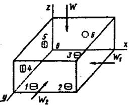
Rice. 2 - Scheme of basing the workpiece in the fixture
on six reference points
These points are in three mutually perpendicular planes: points 1,2, and 3, located in the XOY plane, deprive the part of three degrees of freedom - the ability to move along the OZ axis and rotate around the axes OX, OY; points 4 and 5, located in the ZOY plane, deprive the part of two degrees of freedom - the ability to move along the OX axis and rotate around the OZ axis; point 6, located on the XOZ plane, deprives the part of the sixth degree of freedom - the ability to move along the OY axis. Clamping forces W, W1, W2, acting in directions perpendicular to three planes, press the part against six fixed supports. The number of fixed supports in the fixture should not be more than six, otherwise an unstable position of the workpiece in the fixture is created.
Errors in locating and fixing workpieces in the fixture . The total error in the performance of any machining operation consists of the errors in the installation of the part, the settings of the machine, and the processing error that occurs during the manufacturing process of the part.
Setting error Ey- one of the components of the total error of the performed size of the part - occurs when the workpiece is installed in the fixture and is made up of the basing error Eb, fixing errors Uz and position errors of the part upr, depending on the inaccuracy of the fixture and determined by errors in the manufacture and assembly of its installation elements and their wear during operation.
Machine setting error D n occurs when the cutting tool is set to the size, and also due to the inaccuracy of the copiers and stops for automatically obtaining the specified dimensions of the part.
Processing error D arr., arising during the processing of the part on the machine, is explained by:
1) geometric inaccuracy of the machine;
2) deformation of the technological system machine - fixture - tool - workpiece(AIDS) under the action of cutting forces;
3) inaccuracy in manufacturing and wear of the cutting tool and fixture;
4) temperature deformations of the technological system. To obtain suitable parts, the total error in the processing of the part on the machine must be less than the tolerance b for the given size of the part. This condition is expressed by the inequality
![]() .
.
Basing error Еb called the difference in the limiting distances of the measuring base relative to the cutting tool set to a given size of the part. A locating error occurs when the reference mounting base of the workpiece is not aligned with the measuring one. Value Fuck refers to the specified size obtained with the appropriate scheme for installing the part in the fixture.
 |
Rice. 3 - Examples of installation of workpieces in fixtures with locating errors.
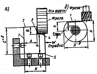
On fig. 3, a the setup diagram is given, in which the side mounting base 1 of the workpiece is simultaneously the measuring base for the surface 3. Therefore, the basing error for size A is zero: Eba=0. The lower support base 5 is the installation base, and the surface 2 serves as the measuring base for the workpiece surface 4. On a tuned machine, the cutter axis occupies a certain position, and the measuring base 2 for a batch of workpieces will change its position from Сmax before Cmin, i.e. within tolerance b for size C. Therefore, the basing error for size B is equal to the tolerance for size C between the installation 5 and measuring 2 bases.
A round part is installed with a hole on a rigid mandrel for processing a flat with a cutter on a milling machine (Fig. 3, b). With such an installation, a gap is formed between the hole of the part and the rigid mandrel of the fixture and a basing error occurs. The measuring base for the machined surface 1 is the axis of the mandrel. Due to the gap S between the workpiece and the mandrel, the axes of the workpiece and the mandrel do not match and the measuring base - the axis of the workpiece can move up and down: when the workpiece is shifted in only one direction, the maximum gap is obtained smax, therefore, the basing error Ebh = Smax .
Mounting error Ез called the difference between the largest and smallest projections of the displacement of the measuring base in the direction of the resulting size due to the application of clamping force W to the workpiece. , intermediate links, housing, fixture mounting and clamping parts, workpiece).
Big influence the fixing error is affected by the shape and dimensions the workpiece, the accuracy and cleanliness of the base surfaces, the design of the fixture and the constancy of the clamping forces of the workpiece. Therefore, fixing errors must be determined experimentally for specific schemes for installing a part in a fixture. When processing parts in fairly rigid fixtures, the fixing error has an insignificant effect on the accuracy of processing and can be ignored in the calculations.
Position error E pr parts relative to the cutting tool arises as a result of inaccurate manufacturing of the fixture, its assembly and wear of the installation elements during operation. Inaccuracies in the manufacture of fixtures arise from errors in the manufacture of its parts, assembly and adjustment. The manufacturing accuracy of the fixture is specified in the working drawing and in the technical specifications.
On the error of overlaying the part in the fixture greatest influence causes wear of its permanent mounting supports. Various details of the device are controlled in a timely manner. When worn, they undergo the appropriate type of repair.
Let us denote the errors in the manufacture of the fixture and the wear of its supports through . Since ,, are the dispersion fields of random variables obeying the normal distribution law, then the installation error as the total dispersion field of the performed part size is determined by the formula
![]() .
.
When choosing a method for installing a part, it is necessary to compare the error obtained for this installation with the permissible error. For the adopted installation scheme, the condition must be met.
2.2 Calculation of actual locating errors when installing parts in a fixture with a flat surface
 |
Rice. 4 - Schemes for determining the errors of basing when installing workpieces in the fixture with a flat surface
The workpiece (Fig. 4, a) is installed on the permanent supports of the fixture lower reference plane 1, which is and measuring base, as it is associated with the treated surface 2 size mm. In this case, the basing error for the size mm obtained after milling is zero and is not included in the total error that affects the accuracy of the size. The workpiece is clamped by force W .
The workpiece (Fig. 4,b) is installed in the fixture lower reference plane 1, but measuring base is the plane 3 , directly related to processed surface 2 size mm. In this case, there is basing error defined in the following way. The size WITH between the cutter axis and the lower mounting reference plane 1 workpiece is constant. Therefore, the position of the cutter axis during surface treatment 2 remains unchanged in relation to the mounting reference surface 1 . Measuring base 3 when milling a plane 2 for a batch of parts will move relative to the outer diameter of the cutter within a tolerance field of 0.40 mm per mm size obtained in the previous operation.
In this case, the dimension tolerance mm between the mounting surface 1
and measuring surface 3
and determine the error of basing the workpiece in the fixture ![]() mm. The error is included in the total error of the mm size obtained with this method installation of the workpiece in the fixture. Consequently, a small value remains on the error of setting the machine and processing:
mm. The error is included in the total error of the mm size obtained with this method installation of the workpiece in the fixture. Consequently, a small value remains on the error of setting the machine and processing:
0.54 - 0.40 = 0.14 mm.
To mill a surface 2 , it is necessary or to eliminate the locating error by setting the workpiece as shown in (Fig. 4, v) or change the tolerances for dimensions and mm. Since to install the part on (Fig. 4, v) is inconvenient and the technologist cannot, without the consent of the designer, increase the tolerance by the size mm, there remains one possibility - to reduce the tolerance by the size mm and, therefore, reduce the error of basing.
The new reduced size tolerance of 65 mm can be found from the equation
![]() ,
,
where and - tolerances for dimensions of 65 and 25 mm;
– total error (excluding basing error),
determined for a size of 25 mm from tables of average economic accuracy of surface treatment of parts.
The technologist puts down the newly accepted tolerance for the size of 65 mm on a certain sketch and gives it to the worker for milling plane 1 in the previous operation. For example, with permission
Therefore, on the operational sketch of the workpiece, dimensions with tolerances and mm must be affixed.
2.3 Calculation of fixtures for accuracy
To ensure the necessary accuracy of the workpiece, when designing a fixture, it is necessary to choose a scheme that satisfies, as mentioned above, the condition
where is the actual value of errors in locating the workpiece in the fixture;
- the permissible value of the errors of basing the workpiece in the fixture.
The allowable value of errors in locating the workpiece in the fixture is approximately calculated by the formula
where is the size tolerance;
– processing error obtained when performing this operation.
In the absence of reasonable data on the accuracy of processing obtained during this operation, the average economic accuracy of processing can be taken.
The actual value of errors in locating the workpiece in the fixture is determined from the geometric relationships inherent in the locating scheme. Calculation formulas for the most common basing schemes are given in the reference data.
The estimated total error of the device is determined by the formula
where is the tolerance on the workpiece;
- coefficient equal to 0.8 - 0.85;
- coefficient equal to 0.6 - 1.0;
– processing error in this operation;
- installation error.
Installation error is the displacement of the workpiece during clamping. It depends on the type of device and, mainly, on the nature of the clamp, and does not depend on the basing scheme and the processing method. The values of the basing error can be selected from reference books. Having determined the basing error and having found the error in the installation of the part and the accuracy of processing from the tables, we calculate the total error of the fixture, which we then distribute among the individual constituent links of the dimensional chain:
![]() ,
,
where is the manufacturing error of fixture parts;
- the error of installing the fixture on the machine;
- error due to structural clearances required for landing on the mounting elements of the fixture;
- the error of skew or displacement of the tool, which occurs due to inaccuracies in the manufacture of the guide elements of the fixture, if there are no guides, the error is not taken into account.
Symbols for basing schemes for typical cases:
clamping device;
Workable surfaces;
![]() main installation bases,
main installation bases,
mounting surfaces.
Etc. - dimensional tolerances a , b , With and etc.
S min– minimum guaranteed clearance;
x- radial beat.
2.4 Rules for choosing bases
In order to reduce the basing error, it is necessary to be guided by the following rules for choosing bases.
1. For parts that are not completely processed, surfaces that cannot be processed should be taken as rough bases. If there are several unmachined surfaces, the one that should have the smallest offset should be taken as the rough base.
2. When processing parts processed completely as a rough base, the surface with the smallest allowance should serve. In this case, there will be the greatest guarantee that there will be no marriage due to a lack of allowance for any surface, since the surfaces with the smallest allowances will be coaxial with the surfaces taken as bases during further processing.
3. Surfaces selected for rough bases should be as even and unbiased as possible. This should also be taken into account in the manufacture of blanks. The appointment of a rough base should be considered only as a means to obtain the first finishing base. It is impossible to re-obtain the position of the workpiece, the same as the first installation, using the rough base, therefore, re-installation using the rough base is unacceptable. The next installation should be done on a finishing basis.
4. First of all, constructive bases should be used as finishing bases and it should be transferred to technological bases only in the complete absence of the possibility to confine ourselves to constructive bases.
5. Of great importance is the condition of the unity of the bases, which consists in processing the maximum number of surfaces when installed on the same base surfaces. If the parts have several surfaces for the finishing base, you must select a surface with a smaller tolerance.
6. It is necessary to combine the installation and measuring bases, since this eliminates the basing error.
7. The selected mounting surfaces should ensure that there are no deformations of the part, which may be caused by the action of the clamping force or cutting forces, as well as the simplicity of design and the low cost of manufacturing the fixture.
3 GENERAL INFORMATION ABOUT DEVICES.
TYPES OF DEVICES
In mechanical engineering, a variety of technological equipment is widely used, which includes fixtures, auxiliary, cutting and measuring tools.
Devices are called additional devices used for machining, assembly and control of parts, assembly units and products. According to the purpose, the devices are divided into the following types:
1. Machine fixtures used to install and fix workpieces on machine tools. Depending on the type of machining, these devices, in turn, are divided into devices for drilling, milling, boring, turning, grinding machines, etc. Machine tools make up 80 ... 90% of the total stock of technological equipment.
The use of devices provides:
a) increasing labor productivity by reducing the time for setting and fixing workpieces with partial or complete overlap of auxiliary time with machine time and reducing the latter through multi-site processing, combining technological transitions and increasing cutting conditions;
b) increasing the accuracy of processing due to the elimination of alignment during installation and associated errors;
c) facilitating the working conditions of machine operators;
d) expansion of technological capabilities of equipment;
e) improving work safety.
2. Devices for installing and fixing a working tool that communicate between the tool and the machine, while the first type connects the workpiece with the machine. With the help of devices of the first and second types, the technological system is adjusted.
3. Assembly devices for connecting mating parts into assembly units and products. They are used for fastening the base parts or assembly units of the assembled product, ensuring the correct installation of the connected elements of the product, pre-assembly of elastic elements (springs, split rings, etc.), as well as for making connections with an interference fit.
4. Control devices for intermediate and final control of parts, as well as for control of assembled parts of machines.
5. Devices for gripping, moving and turning over workpieces and assembly units used in the processing and assembly of heavy parts and products.
By operational characteristics machine tools are divided into universal ones, designed for processing a variety of workpieces (machine vice, chucks, dividing heads, rotary tables, etc.); specialized, designed for processing workpieces of a certain type and representing interchangeable devices (special vice jaws, shaped cams for chucks, etc.), and special ones, designed to perform certain machining operations of a given part. Universal devices are used in conditions of single or small-scale production, and specialized and special devices are used in conditions of large-scale and mass production.
With a unified system of technological preparation for production, machine tools are classified according to certain criteria (Fig. 5).
Universal prefabricated fixtures (USP) are assembled from prefabricated standard elements, parts and assembly units of high precision. They are used as special short-term devices for a specific operation, after which they are disassembled, and the delivering elements are subsequently reused in new layouts and combinations. Further development of USP is associated with the creation of aggregates, blocks, individual special parts and assembly units, providing the layout of not only special, but also specialized and universal adjustment devices of short duration,
Collapsible fixtures (PSA) they are also assembled from standard elements, but less accurate, allowing local refinement according to the seats. These devices are used as special long-term devices. After disassembly, new layouts can be created from the elements.
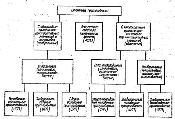
Rice. 5 - Classification of machine tools
Non-separable special devices (NSP) are assembled from standard parts and assembly units of general purpose, as irreversible long-term devices. Structural elements assemblies that are part of the system, as a rule, are operated until they are completely worn out and are not reused. The layout can also be made by building a device from two main parts: a unified base part (UB) and a replaceable setup (SN). This design of the NSP makes it resistant to changes in the design of the workpieces being processed and to adjustments in technological processes. In these cases, only the interchangeable adjustment is replaced in the fixture.
Universal non-adjustment devices (UBD) general purpose are most common in mass production. They are used for fixing blanks from shaped rolled products and piece blanks. UBP are universal adjustable housings with permanent (non-removable) base elements (cartridges, vise, etc.) included in the machine kit when it is delivered.
Specialized adjustment devices (SNP) equip operations for processing parts grouped according to design features and basing schemes; the layout according to the aggregation scheme is a basic housing design with interchangeable settings for groups of parts.
Universal setting devices (UNP), as well as SNPs, have permanent (body) and replaceable parts. However, the replacement part is suitable for only one machining operation on one part only. When switching from one operation to another, the devices of the UNP system are equipped with new replaceable parts (adjustments).
Aggregate Means of Mechanization of Clamping (ASMZ) are a complex of universal power devices made in the form of separate units, which, in combination with devices, make it possible to mechanize and automate the process of clamping workpieces.
The choice of fixture design largely depends on the nature of production. So, in serial production, relatively simple fixtures are used, designed mainly to achieve a given accuracy in processing a workpiece. In mass production, high demands are placed on fixtures in terms of productivity. Therefore, such devices, equipped with quick-action clamps, are more complex structures. However, the use of even the most expensive devices is economically justified.
4. MAIN ELEMENTS OF DEVICES
There are the following fixtures:
installation- to determine the position of the machined surface of the workpiece relative to the cutting tool;
clamping- to fix the workpiece;
guides- to give the required direction of movement of the cutting tool relative to the surface being machined;
fixture housings- the main part, on which all the elements of the devices are placed;
fixing- for connecting individual elements to each other;
dividing or rotary, - to accurately change the position of the machined surface of the workpiece relative to the cutting tool;
mechanized drives- to create clamping force. In some devices, the installation and clamping of the workpiece being processed is performed by one mechanism, called the installation-clamping mechanism.
4.1 Attachment fittings
4.1.1 Basic rules for setting workpieces
Machining is carried out with the relative movement of the workpiece and the cutting tool. To ensure the specified accuracy of processing, the workpiece must be installed in a certain position relative to the cutting tool. After installation, the workpiece is fixed, which prevents its displacement under the action of forces arising during the processing.
In single and small-scale production, workpieces are installed with alignment on rough or machined surfaces, as well as on markings. In mass and large-scale production, alignment is not performed, and the workpieces being processed are installed, bringing their base surfaces to contact with the mounting elements (supports) of the fixtures. In this case, the installation takes less time and the permanent position of the mounting base surfaces of the workpieces in the fixture is ensured.
Depending on the processing conditions, it may be necessary to completely or partially orient the workpiece relative to the cutting tool. With full orientation, the workpiece is given a completely defined and only possible position in the fixture. With partial orientation, precise installation in certain directions is not necessary, and even an arbitrary position (rotation) of the workpiece relative to any axis is acceptable. In this case, the installation scheme and the design of the fixture are simplified.
With full orientation, the base surfaces of the workpiece being machined fit snugly against the mounting elements of the fixture. To do this, the contact conditions of the bases and supports must be observed, and the workpiece must not have a shift and rotation about three coordinate axes. The workpiece being processed is deprived of all degrees of freedom, and the position of its base surfaces in space is certain. The number of supports should be six (six-point rule); their mutual arrangement ensures the stability of the installation of the workpiece in the fixture. The distance between the supports is taken as large as possible so that under the action of gravity there is no overturning moment.
When processing non-rigid workpieces or when their stability is insufficient due to the small length of the base surfaces, it may be necessary to increase the number of reference points (over six). In these cases, additional supports, adjustable or self-aligning, are used. When installing the workpiece to be processed, they are brought to its surface and fixed for the duration of this operation - these supports turn into rigid ones.
Mounting elements with point bearings have a limited contact surface. Such supports include, for example, narrow prisms for holding cylindrical workpieces. These supports provide constant stability of the installation for all blanks of a given batch, regardless of the errors in their sizes and shapes. The disadvantages of mounting on point supports are damage to the base surfaces of the workpieces at high pressing forces, as well as mixing of the workpiece due to deformations at the points of contact of the supports with the bases.
The workpiece to be machined is also installed on the enclosing or covered base surfaces. In this case, the workpiece is put on or inserted into the mounting element with some clearance. To deprive the workpiece of all degrees of freedom, combined methods are also used, for example, installation: a) on two base holes and a plane perpendicular to their axes; b) on a finger and two planes; c) on the hole, plane and support for angular fixation; d) on the outer cylindrical surface, end face and corner support.
In cases where the base is the surface to be treated, removable (movable) installation elements are used.
Thus, the installation elements of fixtures must meet the following basic requirements:
1) the number and location of the mounting elements should provide the necessary orientation and stability of the workpiece to be processed according to the accepted basing scheme;
2) when using draft bases with surface roughness Rz>=40 µm, the mounting elements should be made with a limited support surface in order to reduce the influence of errors and irregularities of these bases on the stability of the installation;
3) installation elements (both basic and additional) must be rigid and wear-resistant, but must not damage the base surfaces, which is especially important when installing on precision and finishing bases that are not subject to further processing;
4) to simplify the repair of the fixture, the installation elements should be easily removed.
4.1.2 Types of installation elements of fixtures
For installation on draft bases, constant (Fig. 6) and adjustable supports are used. Installation on cleanly machined bases is carried out using support plates (Fig. 7) and pins with flat and spherical heads. The dimensions of the supports shown in fig. 4.1 and 4.2, the following: D=6...40 mm; d=4...25 mm; H=10...76 mm; h=4...40 mm; R=4...40 mm; L=60...220 mm; B=16...35 mm; h 1 \u003d\u003d 10 ... 25 mm.

Rice. 6 - Permanent supports
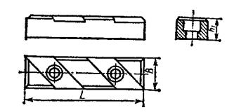 |
Rice. 7 - Adjustable feet
On fig. 8 shows the design of the input support. Support lifting 2 until contact with the base surface of the workpiece is made by moving the wedge 1 using the screw 5 with the handwheel 6. The support is fixed by tightening the screw, while the ball 4 wedges the segment keys 3 and locks the horizontal wedge.
In a self-aligning support (Fig. 9), the vertical pin 1, being under the influence of a pre-compressed spring 4, moves up until it comes into contact with the surface of the workpiece. The dimensions of the spring and the degree of its precompression are selected so that the workpiece does not move when the pin is lifted. By tightening screw 3, the support is fixed in a certain position. An intermediate cracker 2 limits the movement of the pin 1 upwards when the screw is unscrewed.
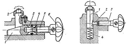
Rice. 8 - Design of the support to be brought in. Fig. 9 - Self-aligning
On the outer cylindrical surfaces, the workpieces are installed in prisms. For purely processed bases, wide prisms are used (Fig. 10, a), for roughing - narrow (Fig. 10, b); in fig. 10, v the method of mounting the workpiece 2 on four permanent supports 3 pressed into the side surfaces of the prism 1 is shown. In fixtures, mainly rigid prisms with an angle a=90 0 are used.
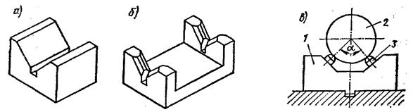
Rice. 10 - Schemes of prisms
Prisms are made of grade 45 steel or hardened steels 08...20 with side surfaces hardened to HRC 50...60 hardness. Prisms of large sizes are made of gray cast iron with hardened cheeks screwed on. Based errors when installed in a prism depend on the tolerance for the diameter of the workpiece, as well as on the errors of its shape.
Installation of workpieces based on holes is carried out on pins or mandrels. Thrust bases are the end surface of the workpiece, which determines its position along the length, and various elements (keyway, hole, etc.) that determine the angular position of the workpiece relative to the axis of the main base.
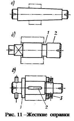 Examples of rigid mandrels are shown in fig. 11. In fig. 11, a shows a conical mandrel (taper 1/1500 ... 1/2000), on which the workpiece is hammered with light blows. Due to the wedging action of the mandrel, the workpiece is kept from turning during processing. The disadvantage of this mandrel is the lack of precise orientation of the workpiece along the length. On fig. eleven, b the design of the mandrel is shown, on which the workpiece is mounted with an interference fit. Using thrust rings (not shown in the figure) during pressing, the workpiece is accurately oriented along the length of the mandrel. With groove 1, both ends of the workpiece can be trimmed. Neck 2 (guide) provides free putting on the workpiece manually. On fig. eleven, v a mandrel is shown on which the workpiece is mounted with a gap.
The position of the workpiece along the length is determined by the shoulder 1 of the mandrel, its turning is prevented by tightening the nut 3 or key 2 (if the workpiece has a keyway). When using these mandrels, it is recommended to machine the base holes of the workpieces according to the 7th grade of accuracy.
Mandrels are recommended to be made of hardened steel and carefully ground. It is advisable to provide protective chamfers in the center sockets in order to protect them from accidental damage. To bring the mandrel into rotation, a square is made at its end, flats or a driving pin is pressed in.
| |
Nut 1 limits the movement of the collet to the left. On fig. 12, b the design of the cantilever expanding mandrel is shown. The workpiece 1 is fixed by tightening the inner cone 2. Expanding mandrels provide less concentricity of processing compared to rigid ones. On fig. 12, v the design of a cantilevered mandrel with three biscuits 1, moved apart by an internal cone 2 is shown . This mandrel is used to install thick-walled workpieces. A mandrel with an elastic sleeve expanded from the inside by a hydroplastic is shown in fig. 12, G. By tightening the screw 3, the hydroplastic 1 is compressed, which, by expanding the thin-walled sleeve 2, firmly fixes the workpiece. Mandrels with hydroplastic provide a high degree of concentricity (runout 0.005...0.01 mm).

Rice. 12 - Expanding mandrels
The installation of blanks on the base holes in stationary fixtures is carried out on cantilever fingers. On fig. thirteen, a, b constants are shown, and in Fig. thirteen, c, g - interchangeable fingers. To facilitate putting on workpieces, a chamfer is removed at the end of the finger.
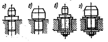
Rice. 13 - Examples of cantilever fingers
Installation errors on the fingers can be expressed in the displacement of the workpieces in the radial direction by the size of the gap between the mating surfaces. If the base end of the workpiece is not perpendicular to the axis of the hole, then the axis of the hole may be misaligned with respect to the axis of the pin.
When processing blanks of plates, frames, beds, body and other parts, installation is used for two holes with parallel axes and a plane perpendicular to them. She provides simple design devices, the principle of constancy of bases and fixation of workpieces during processing on machine tools and automatic lines. The base plane of the workpiece is machined clean, and the holes are deployed according to the 7th grade of accuracy. The installation elements are two fingers (rigid or retractable) and support bars. circuit diagram installation is shown in fig. 14, a. One of the fingers is cylindrical, and the other is rhombic, since the presence of a tolerance for the distance between the axes of the base holes leads to the fact that one of the holes (for example, the right one; Fig. 14, b) can take two limit positions formed by two circles when installing a batch of blanks a and b. If the right finger is taken with a circular section, then its diameter is equal to d - d; in this case, it is possible to rock the workpiece on the left finger from the middle position by a size of ± d/2. A more advantageous shape of the right finger will be rhombic (Fig. 14, v) .

Rice. 14 - Schematic diagram of the installation
The swaying of the workpiece in this case is equal to
![]() .
.
A rhombic finger in cross section has a small ribbon, half the width of which is determined by the following formula
![]() ,
,
where d 1 - tolerance for the size L of the workpiece;
d a- tolerance for size L of the fixture;
2 D 1 - diametrical clearance when the workpiece is seated on a cylindrical pin at d 1 +d 2 >2D 1 . If this condition is not met, then the use of a rhombic finger is impossible.
The largest possible angle of distortion of the workpiece from the middle position due to gaps when landing on the fingers (Fig. 14, G) can be determined by the formula
![]()
or approximately
![]() .
.
Thus, to decrease a, it is advisable to increase the distance L.
When processing shafts and some other workpieces with base surfaces in the form of center sockets (or conical chamfers), centers are used as setting elements. Various constructive forms of centers are shown in fig. 15. Scheme of installation on a conventional hard center shown in fig. 15, a; in fig. 15, b shows the installation of the workpiece with a conical chamfer on cut center; in fig. 15, v - design rotating, center for turning works; in fig. 15, G- installation of the workpiece on a special, cut center with teeth and in fig. 15, d- design leader center for torque transmission due to the introduction of corrugations into the base surface of the workpiece seat. This center provides a large torque transmission, but spoils the surface of the socket. For accurate installation of workpieces along the length, they are used floating front center(Fig. 15, e). In this case, the error in the diameter of the center seat does not affect the axial displacement of the workpiece, since the end face of the latter rests against the fixed plane of the body of the floating center.
When installed on two centers, the workpiece retains one degree of freedom - the possibility of rotation around the axis of the centers. In some cases (keyway milling, square milling) an additional base is needed for the angular coordination of the workpiece. On fig. 16 shows the installation of the workpiece with clamping to the additional side base.

Rice. 15 - Various constructive forms of centers
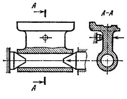
Rice. 16 - Installation of the workpiece with clamping to the additional side base
Complete orientation of the workpiece in space is provided by installation on three centers (Fig. 17, a), of which two are rigid, and one is retractable, acting as an installation and clamping element. The advantages of this scheme are good stability and constancy of the bases, since after the preparation of the center sockets, all operations can be performed at one base. The disadvantages of the scheme include the need to maintain the exact value of the diameter of the center slots.
The basing scheme can also be carried out by installing on four centers (Fig. 17, b), of which two are rigid and two are retractable. This scheme is less sensitive to changes in the diameter of the center pockets, since the gap can be chosen, and the axis of the part can shift in this case.
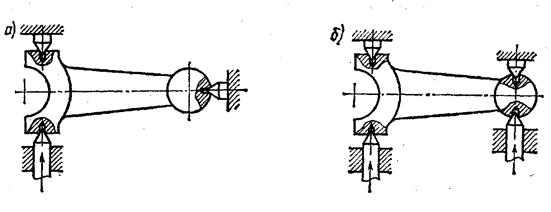
Rice. 17 - Scheme of the complete orientation of the workpiece in space
When grinding the axial holes of the gears, basing on the working surfaces of the teeth is used, thereby ensuring a high concentricity of the hole of the gear. On fig. 18 shows various gear setups. Rails are used as installation elements (Fig. 18, a), rollers (Fig. 18, b) jagged sectors (Fig. 18, v) and swing arms (Fig. 18, G) in special cartridges (for cylindrical wheels).
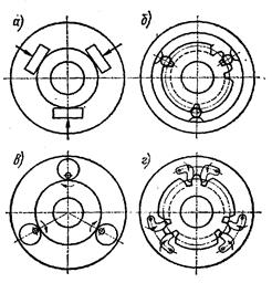
Rice. 18 - Various arrangements of gears
When using rollers, cartridges are used (Fig. 19), where the installation elements, in this case the rollers, are fixed in the holder 4 , allowing the possibility of their self-alignment along the hollows of the wheel 5 . Precise centering provided by 3 cams , which slide along the inclined grooves of the cartridge body. The axial orientation of the workpiece is carried out along the stops 6 . When fixing the workpiece, the force from the rod 1 is transmitted through the flexible plates 2 to the cams.
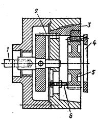
Rice. 19 - Cartridge scheme
Bevel gears are mounted on spherical elements. using special clamping devices (Fig. 20).

Rice. 20 - Scheme of the clamping device
In some cases, external and internal spherical surfaces, external and internal threaded and splined surfaces, shaped surfaces, as well as their various combinations, can be used as mounting bases.
4.2 Clamping elements of fixtures
4.2.1 Purpose of clamping elements
The main purpose of clamping devices is to ensure reliable contact of the workpiece with the mounting elements and prevent its displacement relative to them and vibration during processing. The introduction of additional clamping devices increases the rigidity of the technological system and thereby achieves an increase in the accuracy and productivity of processing, and a decrease in surface roughness. On fig. 21 shows a diagram of the installation of workpiece 1, which, in addition to the two main clamps Q1, is fixed with an additional device Q2, which imparts greater rigidity to the system. Support 2 is self-aligning.
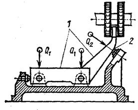
Rice. 21 - Scheme of setting the workpiece
Clamping devices are in some cases used to ensure correct installation and centering of the workpiece. In this case, they perform the function of mounting and clamping devices. These include self-centering chucks, collets, etc.
Clamping devices are not used when processing heavy, stable workpieces, in comparison with the mass of which the forces arising during the cutting process are relatively small and are applied in such a way that they cannot disturb the installation of the workpiece.
Clamping devices of fixtures must be reliable in operation, simple in design and easy to maintain; they should not cause deformations of the fixed workpiece and damage to its surface, they should not shift the workpiece in the process of its fixing. The machine operator must spend a minimum of time and effort on fixing and detaching workpieces. To simplify the repair, it is advisable to make the most wear parts of the clamping devices replaceable. When fixing workpieces in multi-place fixtures, they are clamped evenly; with limited movement of the clamping element (wedge, eccentric), its stroke must be greater than the tolerance for the size of the workpiece from the mounting base to the place where the clamping force is applied.
Clamping devices are designed taking into account safety requirements.
The place of application of the clamping force is chosen according to the condition of the greatest rigidity and stability of the fastening and the minimum deformation of the workpiece. When increasing the accuracy of processing, it is necessary to observe the conditions for a constant value of the clamping force, the direction of which must be recognized with the arrangement of the supports.
4.2.2 Types of clamping elements
Clamping elements are mechanisms directly used to clamp workpieces, or intermediate links in more complex clamping systems.
The simplest kind universal clamps are clamping screws that are driven by keys, handles or handwheels mounted on them.
To prevent movement of the clamped workpiece and the formation of dents on it from the screw, as well as to reduce the bending of the screw when pressing on a surface that is not perpendicular to its axis, rocking shoes are placed on the ends of the screws (Fig. 22, a).
Combinations screw devices with levers or wedges are called combined clamps, a type of which are screw clamps (Fig. 22, b). The clamping device allows you to move or rotate them so that you can more conveniently install the workpiece in the fixture.
![]()
Rice. 22 - Schemes of screw clamps
On fig. 23 shows some quick clamp designs. For small clamping forces, a bayonet is used (Fig. 23, a), and for significant forces - a plunger device (Fig. 23, b). These devices allow the clamping element to be retracted a long distance from the workpiece; fastening occurs as a result of the rotation of the rod through a certain angle. An example of a clamp with a folding stop is shown in fig. 23, v. Loosen the nut-handle 2 , take away emphasis 3 , rotating it around its axis. After that, the clamping rod 1 is retracted to the right at a distance h . On fig. 23, G a diagram of a high-speed lever-type device is given. When the handle 4 is turned, the pin 5 slides along the bar 6 with an oblique cut, and the pin 2 - by workpiece 1 , pressing it against the stops located below. Spherical washer 3 serves as a hinge.
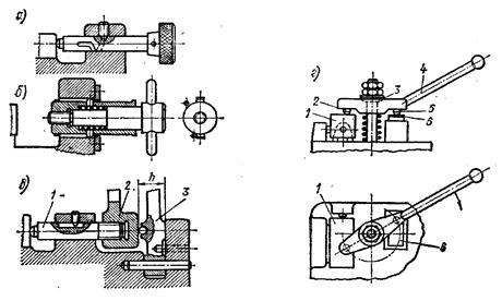
Rice. 23 - Constructions of quick clamps
The time consuming and significant forces required to clamp workpieces limit the application of screw clamps and in most cases make quick-acting eccentric clamps preferable. On fig. 24 shows a disk ( a), cylindrical with L-shaped clamp ( b) and conical floating ( v) clips.
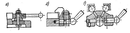
Rice. 24- Various designs clamps
Eccentrics are round, involute and spiral (according to Archimedes' spiral). In clamping devices, two types of eccentrics are used: round and curved.
Round eccentrics (Fig. 25) are a disk or roller with an axis of rotation shifted by the size of the eccentricity e; the self-braking condition is provided at the ratio D/e ≥ 4.
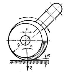
Rice. 25 - Diagram of a round eccentric
The advantage of round eccentrics lies in the ease of their manufacture; the main disadvantage is the inconsistency of the angle of elevation a and the clamping forces Q. Curvilinear eccentrics, the working profile of which is carried out according to the involute or Archimedes spiral, have a constant angle of elevation a, and, therefore, ensure the constancy of the force Q when clamping any point of the profile.
The wedge mechanism is used as an intermediate link in complex clamping systems. It is easy to manufacture, easily placed in the device, allows you to increase and change the direction of the transmitted force. At certain angles, the wedge mechanism has self-braking properties. For a single-sided wedge (Fig. 26, a) when transferring forces at a right angle, the following dependence can be adopted (for j1=j2=j3=j, where j1...j3 are friction angles):
where P - axial force;
Q - clamping force.
Self-braking will take place at a For a double-beveled wedge (Fig. 26, b) when transferring forces at an angle b> 90 °, the relationship between P and Q at a constant friction angle (j1=j2=j3=j) is expressed by the following formula P \u003d Q sin (a + 2j / cos (90 ° + a-b + 2j). Lever clamps are used in combination with other elementary clamps, forming more complex clamping systems. Using the lever, you can change the magnitude and direction of the transmitted force, as well as carry out simultaneous and uniform clamping of the workpiece in two places. Rice. 26 - Schemes of a single-sided wedge ( a) and a double wedge (b) On fig. 27 shows the diagrams of the action of forces in one-arm and two-arm straight and curved clamps. The equilibrium equations for these lever mechanisms are as follows: for one shoulder clamp (Fig. 27, a) for straight two-arm clamp (Fig. 27, b) for two-arm curved clamp (for l1 where r
-
friction angle; f- coefficient of friction. Rice. 27 - Schemes of the action of forces in one-arm and two-arm straight and curved clamps Centering clamping elements are used as mounting elements for the outer or inner surfaces of bodies of revolution: collets, expanding mandrels, clamping sleeves with hydroplastic, and also membrane cartridges. The collets are split spring sleeves, the design variations of which are shown in fig. 28 ( a- with tension tube; b - with spacer tube; v- vertical type). They are made of high-carbon steels, for example, U10A, and are heat-treated to a hardness of HRC 58...62 in the clamping and to a hardness of HRC 40...44 in the tail parts. Collet cone angle a=30. . .40°. At smaller angles, collet jamming is possible. The taper angle of the compression sleeve is made 1° less or greater than the taper angle of the collet. Collets provide installation eccentricity (runout) no more than 0.02...0.05 mm. The base surface of the workpiece should be machined according to the 9th...7th grade of accuracy. Expanding mandrels of various designs (including designs using hydroplastic) are classified as clamping fixtures (see chapter 4.1). Membrane cartridges are used for precise centering of workpieces on the outer or inner cylindrical surface. The cartridge (Fig. 29) consists of a round membrane 1 screwed to the faceplate of the machine in the form of a plate with symmetrically located protrusions-cams 2 ,
the number of which is chosen within 6...12. A rod of 4 pneumatic cylinders passes inside the spindle. When the pneumatics are turned on, the membrane flexes, pushing the cams apart. When the rod moves back, the membrane, trying to return to its original position, compresses the workpiece 3 with its cams. Rice. 29 - Scheme of the diaphragm cartridge The rack-to-lever clamp (Fig. 30) consists of a rack 3, a gear wheel 5 sitting on a shaft 4, and a handle lever 6. By turning the handle counterclockwise, the rack is lowered and the workpiece 1 is fixed with a clamp 2. The clamping force Q depends on the value force P applied to the handle. The device is equipped with a lock, which, jamming the system, prevents the wheel from turning back. The most common types of locks are: Rice. 30 - Rack and pinion clamp Roller lock (Fig. 31, a) consists of a driving ring 3 with a cutout for the roller 1, which is in contact with the cut plane of the shaft 2 of the gear. The driving ring 3 is fastened to the handle of the clamping device. Rotating the handle in the direction of the arrow, the rotation is transmitted to the gear shaft through the roller 1. The roller is wedged between the bore surface of the housing 4 and the cut plane of the roller 2 and prevents reverse rotation. Rice. 31 - Diagrams of various designs of locks A roller lock with direct transmission of torque from the driver to the roller is shown in fig. 31, b. The rotation from the handle through the leash is transmitted directly to the shaft 6 of the wheel. Roller 3 is pressed through pin 4 by a weak spring 5. Since the gaps at the points of contact of the roller with ring 1 and shaft 6 are chosen, the system instantly wedges when the force is removed from handle 2. By turning the handle in the opposite direction, the roller wedges and rotates the shaft clockwise . Conical lock (Fig. 31, v) has a conical bushing 1 and a shaft 2 with a cone 3 and a handle 4. The spiral teeth on the middle neck of the shaft are engaged with the rail 5. The latter is connected to the actuating clamping mechanism. When the angle of inclination of the teeth is 45°, the axial force on the shaft 2 is equal (excluding friction) to the clamping force. Eccentric lock (Fig. 31, G) consists of a wheel shaft 2, on which an eccentric 3 is wedged. The shaft is driven by a ring 1 fastened to the lock handle; the ring rotates in the body bore 4,
the axis of which is displaced from the axis of the shaft by a distance e .
With the reverse rotation of the handle, the transmission to the shaft occurs through pin 5. In the process of fixing, ring 1 is wedged between the eccentric and the body. Combined clamping devices are a combination of elementary clamps of various types. They are used to increase the clamping force and reduce the dimensions of the device, as well as to create the greatest ease of management. Combined clamping devices can also provide simultaneous clamping of the workpiece in several places. Types of combined clamps are shown in fig. 32. The combination of a curved lever and a screw (Fig. 32, a) allows you to simultaneously fix the workpiece in two places, evenly increasing the clamping forces to a predetermined value. Conventional swivel clamp (Fig. 32, b) is a combination of lever and screw terminals. The swing axis of the lever 2 is aligned with the center of the spherical surface of the washer 1, which unloads the pin 3 from bending forces. Shown in fig. 32, v An eccentric clamp is an example of a quick combination clamp. With a certain lever arm ratio, the clamping force or stroke of the clamping end of the lever can be increased. Rice. 32 - Types of combination clamps On fig. 32, G shows a device for fixing a cylindrical workpiece in a prism by means of a cap lever, and in fig. 32, d - Scheme of a high-speed combined clamp (lever and eccentric), which provides lateral and vertical pressing of the workpiece to the fixture supports, since the clamping force is applied at an angle. A similar condition is provided by the device shown in Fig. 32, e. Toggle clamps (Fig. 32, f, h, i) are examples of quick action clamping devices operated by turning a handle. To prevent self-detachment, the handle is moved through the dead position until it stops 2 .
The clamping force depends on the deformation of the system and its rigidity. The desired deformation of the system is set by adjusting the pressure screw 1. However, the presence of a tolerance on the size H(Fig. 32, g) does not provide a constant clamping force for all workpieces in a given batch. Combined clamping devices are operated manually or from power units. Clamping mechanisms for multiple fixtures must provide the same clamping force in all positions. The simplest multi-place device is a mandrel, on which a package of blanks (rings, disks) is mounted, fixed along the end planes with one nut (sequential clamping force transmission scheme). On fig. 33, a shows an example of a clamping device operating on the principle of parallel clamping force distribution. If it is necessary to ensure the concentricity of the base and workpiece surfaces and prevent deformation of the workpiece, elastic clamping devices are used, where the clamping force is uniformly transmitted by means of a filler or other intermediate body to the clamping element of the fixture (within the limits of elastic deformations). Rice. 33 - Clamping mechanisms for multiple fixtures Conventional springs, rubber or hydroplastic are used as an intermediate body. A parallel action clamping device using hydraulic plastic is shown in fig. 33, b. On fig. 33, v a device of mixed (parallel-sequential) action is given. On continuous machines (drum-milling, special multi-spindle drilling), workpieces are installed and removed without interrupting the feed movement. If the auxiliary time overlaps with the machine time, then various types of clamping devices can be used to secure the workpieces. For the purpose of mechanization production processes it is advisable to use clamping devices of an automated type (continuous action), driven by the feed mechanism of the machine. On fig. 34, a shows a diagram of a device with a flexible closed element 1 (cable, chain) for fixing cylindrical workpieces 2 on a drum-milling machine when processing end surfaces, and in fig. 34, b- diagram of a device for fixing piston blanks on a multi-spindle horizontal drilling machine. In both devices, operators only install and remove the workpiece, and the clamping of the workpiece occurs automatically. Rice. 34 - Automated clamping devices An effective clamping device for holding thin sheet workpieces during their finishing or finishing is a vacuum clamp. The clamping force is determined by the formula where A- active area of the cavity of the device, limited by the seal; p
\u003d 10 5 Pa- the difference between atmospheric pressure and pressure in the cavity of the device from which air is removed. Electromagnetic clamping devices are used to clamp workpieces made of steel and cast iron with a flat base surface. Clamping devices are usually made in the form of plates and cartridges, in the design of which the dimensions and configuration of the workpiece in plan, its thickness, material and the required holding force are taken as initial data. The holding force of the electromagnetic device largely depends on the thickness of the workpiece; at small thicknesses, not all of the magnetic flux passes through the cross section of the part, and part of the magnetic flux lines is scattered into the surrounding space. Parts processed on electromagnetic plates or cartridges acquire residual magnetic properties - they are demagnetized by passing them through a solenoid powered by alternating current. In magnetic clamping devices, the main elements are permanent magnets, isolated from each other by non-magnetic spacers and fastened into a common block, and the workpiece is an anchor through which the magnetic power flow is closed. To detach the finished part, the block is shifted using an eccentric or crank mechanism, while the magnetic force flow closes to the device body, bypassing the part. When performing some machining operations (drilling, boring), the rigidity of the cutting tool and the technological system as a whole is insufficient. Guide elements are used to eliminate the pressing of the tool. They must be accurate, wear-resistant and, with a large production program, replaceable. Such elements of fixtures are jig bushings for drilling and boring fixtures. Design and dimensions bushings for drilling are standardized. Bushings are permanent (Fig. 35, a) and interchangeable (Fig. 35, b). Permanent bushings are used in small-scale production when machining a hole with one tool. Replaceable bushings are used in mass and large-scale production. Quick-change sleeves with a lock (Fig. 35, b) are used when machining a hole with several successively replaceable tools. Replaceable and quick-change bushings are inserted into permanent bushings pressed into the fixture body. Rice. 35 - Diagrams of drill bushings With a hole diameter of up to 25 mm, the bushings are made of U10A steel, hardened to a hardness of HRC 60 ... Estimated service life of conductor bushings is 10...15 thousand drillings. If the tools are guided in the sleeve not by the working part, but by cylindrical centering sections, the sleeve hole is made with tolerances according to the hole system. To determine the maximum dimensions of the hole, tolerances for the diameter of the tool are taken in accordance with the relevant GOSTs. The eccentricity of the outer surface of the sleeve with respect to the hole should not exceed 0.005 mm. Between the lower end of the sleeve and the surface of the workpiece leave a gap from l /z
d before d, and when drilling deep holes in steel, up to 1.5d (here d- bore diameter). The seating surfaces of the bushings are processed by grinding (Ra=1>25...0.32 µm). The surface of the hole for the passage of the tool is trimmed (Ra=0.32...0.08 µm) to increase the service life of the bushing. Examples of special bushings are shown in fig. 36. In fig. 36, a sleeve for drilling holes on inclined surfaces is shown; elongated quick-change sleeve (Fig. 36, b) is used if a hole is processed in the recess of the workpiece; with a small distance between the axes of the holes, cut bushings are used (Fig. 36, v) or one block (Fig. 36, G). Rice. 36 - Examples of special bushings To guide the boring bars (boring bars), fixed and rotating bushings are used. On fig. 37, a the design of a rotating sleeve is shown, the sliding surface of which is protected from chips. On fig. 37, b shows a sleeve mounted on rolling bearings. In both designs, a groove for the boring bar key is cut on the inner surfaces; this ensures forced rotation of the bushings. To facilitate the entry of the key into the groove of the sleeve, the latter is often made with beveled edges or floating. Grooves are often provided on the inner surface of the sleeve for the passage of protruding cutters-boards. Rice. 37 - Schemes of rotating (a) and fixed (b) bushings The guide elements of the devices also include copiers used in the processing of shaped surfaces of a complex profile. Their task is to guide the cutting tool along the workpiece surface to be machined to obtain a given trajectory of their movement. 4.4 Dividing and turning elements of fixtures Dividing and rotary devices in multi-position fixtures are used to change the position of the workpiece relative to the working tool. The dividing device consists of a disk fixed on the rotary part of the device and a latch. Designs of clamps are shown in fig. 38. Ball retainer (Fig. 38, a) is the simplest, but does not provide high accuracy of the angle of rotation and does not perceive the moment from the cutting force. The rotary part is set to a predetermined position manually until it clicks when the ball falls into the socket. Retainer with pull-out cylindrical pin (Fig. 38, b) can sense torque, but it does not provide highly accurate divisions due to gaps in the moving joints. A slightly greater accuracy is provided by a retainer with a conical sharpening of the draw finger (Fig. 38, v). Rice. 38 - Designs of clamps To eliminate the radial clearance, a hydroplastic sleeve is introduced G(Fig. 38, G), wedge retainers and slotted retainers are also used (Fig. 38, d).
The latch is controlled using an exhaust button, a handle mounted on a rack and pinion wheel, or a pedal device. In a dividing device for milling machine(Fig. 39) latch 4 is interlocked with turning pawl 2. When the table reciprocates, they are actuated from a fixed stop 3 .
Stop 1 warns that the dividing disc 5 is turned in the opposite direction. Rice. 39 - Diagram of a dividing device for a milling machine To reduce the torque in horizontal type fixtures, the center of gravity of the rotary system (including the workpiece) must lie on the axis of rotation. This is achieved by an appropriate layout of the device and the installation of corrective counterweights. In devices with a vertical axis, the weight of a heavy rotary system is taken up by a thrust rolling bearing. On fig. 40 shows the design of the table, the upper part of which rotates to the required angle when lifted on a thrust ball bearing. Lifting is carried out by various mechanical devices or (as shown in the figure) by a pneumatic cylinder. When lowering, the table "sits" on the end plane of the base and is pressed tightly against it. Using thrust ball bearings, it is possible to reduce the friction moment by several times during the rotation of the rotary part of the device. Rice. 40 - Table construction On fig. 41 shows a mechanical table clamp interlocked with a latch. By turning the handle 4 clockwise, the rack lock 5 is inserted, while simultaneously squeezing the split conical ring 1 ,
and the rotary part 2 of the table is attracted to the base 3 .
When the handle is turned back, the latch is removed from the socket, the tightening of the ring is loosened and the table can be rotated. Rice. 41 - Mechanical clamping device of the table The body is the basic part of the fixture; clamping devices, mounting and guiding elements, as well as auxiliary parts and mechanisms are mounted in it. The housing absorbs the forces generated during machining as well as the clamping forces. The body of the device must have a minimum mass, be rigid and durable. Its design should be convenient for quick installation and removal of workpieces, for cleaning chips and draining coolant. The housing should be simple and cheap to manufacture and meet safety requirements. The cases of movable and tiltable devices are made with cast or plug-in knives that limit the contact surface with the machine table. The dimensions and configuration of the legs in the plank must ensure that the T-slots of the table are covered in any position of the body. For better drainage of the coolant and removal of chips, inclined surfaces are provided in the housings and recesses in the hard-to-reach places. The angle of inclination of these surfaces for cast iron shavings is a=30...35°; for steel chips with oil a=25...50°; for aluminum a=40...45°. The body is usually attached to the machine with bolts that are inserted into the T-slots of the table. In serial production, where different operations are periodically performed on the same machine, the time spent on attaching the housing to the machine should be minimal. To do this, either shelves are made on the body for fixing it with tacks, or cast lugs for fixing bolts. Quick and accurate installation of the fixture on the machine table without alignment is usually provided by guide keys inserted into the T-slot of the table. The keys are made in the form of short crackers, screwed to the lower plane of the body, in order to reduce the distortion of the device due to gaps in the key connections, the distance between the keys should be chosen, possibly large. On fig. 42 shows examples of centering and fastening fixture housings on the spindles of lathes of the turning group: a - cylindrical; b- conical; v - turning. Rice. 42 - Examples of centering and fastening of fixture housings on the spindles of lathe machines: a - cylindrical; b- conical; v - turning Cases of heavy fixtures for ease of grip during installation and removal from the machine are equipped with eyebolts. The simplest cases of devices are a rectangular plate. The housing can be in the form of a faceplate, square, brand, trough, etc. In fixtures for drilling workpieces from several sides, the housings are box-shaped. Cases are made of gray cast iron SCh12-28, steel St3, in some cases (for example, in rotary devices) aluminum alloys are used. Device bodies are made by casting, welding, forging, as well as assembly from individual elements on screws or with an interference fit. Casting is used mainly for cases of complex configuration. With the help of welding, it is also possible to obtain cases of complex configurations, while reducing the time and reducing the cost of their manufacture. Using reinforcing ribs, corners and scarves, it is possible to obtain rigid welded cases. The cost of welded hulls in some cases can be halved compared to cast ones, and the weight is reduced by 40%. On fig. 43 shows examples of cast ( a), welded ( b), prefabricated ( v) and forged ( G) hulls of the same design. The configuration of the welded hull differs little from the cast one, the configurations of the prefabricated and forged hulls are the simplest. 4.6 Powered attachment drives 4.6.1 Purpose of the motorized drive The largest part of the auxiliary time is usually spent on setting up, clamping the workpiece and unfastening the machined part, therefore, along with reducing machine time, it is of great importance downtime reduction. Auxiliary time can be reduced by using mechanized drives, which are divided into mechanical, pneumatic, hydraulic, pneumohydraulic, electromechanical and electromagnetic. The field of application of manually operated mechanical drives is limited by the low achievable clamping forces. Their use in multi-seat fixtures is associated with the creation of complex and bulky structures that require high costs time for clamping and releasing the processed workpieces. The most widely used in mechanical engineering plants are devices with pneumatic and hydraulic drives, which, by means of mechanical gears, provide a reliable clamping of the workpiece at a constant force. 4.6.2 Pneumatic drives The principle of operation of the pneumatic drive is that compressed air from the factory line is supplied to the working cavity of the pneumatic cylinder, presses on the piston and makes it perform the translational movement necessary to clamp the workpiece. When the piston returns to its original position, the part is released from the fixture. Pneumatic cylinders are double-acting and single-acting: in the first case, the piston with the rod acting on the clamping element is returned to its original position by compressed air, and in the second - by a spring. On fig. 44, a a schematic diagram of a double-acting pneumatic actuator is shown. The drive consists of cylinder 1 ,
piston 2 ,
stem 3 ,
switching distribution valve 4 and air duct 5. The drive also includes equipment for connecting the distribution valve to the main line, designed to regulate and control pressure in the network and to clean compressed air from mechanical particles and moisture. This equipment consists of a pressure reducing valve with a pressure gauge, a valve, a filter, an oiler for lubricating cuffs and seals, and an air duct. Distribution valve 4 is a spool device consisting of a body and a spool. The valve openings are located so that in the extreme positions of the spool, one of the cylinder cavities is connected to the air duct, and the opposite one is connected to the atmosphere. For a single-acting cylinder (Fig. 44, b) one hole in the distribution valve is plugged, and in the non-working cavity of the pneumatic cylinder there is a hole for releasing excess air. In this case, the piston returns to its original position by spring 6 .
Rice. 44 - schematic diagrams of a double-sided pneumatic drive ( a) and unilateral ( b) actions The force transmitted by the rod F without taking into account friction losses, they are calculated using the following formulas: for double-acting pneumatic cylinders
F
=
p
. F
=
p
[
p
D
²/4]- for the cavity of the cylinder without a rod; F=p[
p
(
D
²-
d
²)/4]- for the cavity of the cylinder with a rod; for single acting pneumatic cylinders. F
=
- for the cavity of the cylinder without a rod; F=- for the cavity of the cylinder with a rod. Here p is the specific air pressure; D-piston diameter; d - rod diameter; q is the resistance force of the spring. Usually compressed air is supplied at a pressure of 0.5 ... 0.6 MPa (lower pressure necessitates the use of cylinders large diameter), however, the calculation should take into account the simultaneous operation of a number of air consumers, as well as losses in the air duct (network), therefore, the design pressure should be taken as 0.4 MPa. The air consumption with single-acting cylinders is less than with double-acting cylinders. The use of single-acting cylinders is limited by the stroke length of the piston, the speed of its reverse movement and the reduction in the force transmitted by the rod by the amount necessary to compress the return spring. The inner diameter of pneumatic cylinders can be 50, 75, 100, 150, 200, 250 and 300 mm; cylinders with a diameter of less than 50 mm are used in rare cases, for example, to push the machined parts out of the fixture, press workpieces to the mounting surface, etc. An increase in the diameter of pneumatic cylinders over 300 mm leads to a complication of the drive design and an increase in its dimensions, therefore, in cases where a large clamping force is required, it is advisable to use pneumohydraulic drives. Pneumatic cylinders can be stationary, rotating, oscillating and floating. Special cylinder designs are also available. Usually the cylinders are made as independent units, but sometimes the pneumatic cylinder is made in the body of the device (built-in cylinder). Each pneumatic cylinder consists of a body, a piston and a rod. A bushing is installed in the cylinder body, and one or two covers are installed from the ends of the cylinder, which are centered with flanges along inner diameter bushings. To prevent air leakage, the piston and covers are provided with seals. Covers with a sleeve and a body can be connected with studs or bolts that are passed from the outside of the body. In the manufacture of the cylinder body, together with the front cover, the back cover is screwed. The bushing and covers are made of cast iron, steel and aluminum. In the covers, grooves are made with a depth of 3 mm and a diameter of 10 mm for the preliminary accumulation of compressed air during the piston stroke until the back or front cover stops. Pneumatic actuators are usually used with a one-sided rod, i.e. with a rod passing through one of the cylinder covers. The movement of the rod in the pneumatic chamber occurs as a result of the deformation of the diaphragm. A diaphragm pneumatic chamber (Fig. 45) is a body made of two cast or stamped cups, between which a rubber poppet, and sometimes a flat diaphragm, is installed. Washer 4, mounted on rod 6, is pressed by springs 2 and 3 against rubber diaphragm 5. When compressed air is admitted into the chamber body, the diaphragm is deformed and, acting on the washer, transfers pressure to rod 6. The chamber has only one inlet for air that enters through air duct 1 through the distribution valve 7. When switching the distribution valve 7, the air from the chamber escapes into the atmosphere, springs 2 and 3 return the washer with the stem, and hence the diaphragm to its original position. The poppet diaphragm (Fig. 46) is made of a four-layer rubberized fabric. The main dimensions of diaphragms manufactured by industry are given in Table. 1. Flat diaphragms are used only with a small stroke of the rod. The diameter of the chamber washer is taken equal to 0.8
D, a further increase in the diameter of the washer entails a decrease in the stroke of the rod. Pneumatic chambers have a stroke of 30...35 mm. With such a stroke, the pneumatic chambers, depending on the size, without the use of additional mechanisms, develop the following clamping forces: diameter D i, mm.......... 174 200 228, power F
,
kN......... 2.5...3 3...4.5 6...6.5 Table 1 - Main dimensions of disk-shaped rubber diaphragms, mm Rice. 46 - Schematic diagram of a poppet diaphragm Pneumatic chambers are stationary and rotating. The use of rotating chambers reduces not only the mass of the drive and the cantilever load on the spindle, but also the consumption of compressed air. On fig. 47 shows a general view of a rotating cartridge with a diaphragm chamber. Distribution sleeve 1 is attached to chamber 2, and a hole is drilled in the bottom of the chamber for air to enter from the sleeve, while the hole in fitting 9 is plugged. The chamber 2 is attached to the faceplate 3 connected by the slider 8 with the rod 7. The faceplate 6 is mounted on the rear end of the machine spindle, which is connected to the rod 4 of the pneumatic chamber by means of an intermediate strap 5. When air is admitted into the chamber, the workpiece is clamped as a result of the action of compressed air on the rear wall of the pneumatic chamber, which, moving backward, carries along the thrust 7. If it is necessary to convert the pulling force into a pushing force, a pneumatic chamber is used, rigidly connected to the rear faceplate of the machine. The stem of the chamber is directly connected to the rod. Rice. 47 - General view of a rotating cartridge with a diaphragm chamber To increase the clamping force, combined diaphragm pneumatic chambers are used. In this case, several cameras are installed, as shown in Fig. 48. The three-section rotating pneumatic diaphragm chamber includes three stamped chambers welded together, consisting of a cover 4, a chamber 5, a rubber diaphragm 1 with a washer 2, a seal 7 and a sleeve 6 sitting on the shaft 9. In addition, the front chamber is welded to the disk 10, with which the chamber is centered and attached to the faceplate 8. A distribution sleeve 3 is put on the rear end of the shaft 9. To clamp the part, compressed air enters through channel A and holes B into the right parts of the chambers. The increase in clamping force is due to the large total area of the diaphragms. In order to save compressed air to squeeze the part, it is enough to let it in not into all three chambers, but only into the leftmost chamber through hole B. Rice. 48 - Combined diaphragm pneumatic chambers With small sizes of pneumatic cylinders and chambers, and if it is necessary to obtain large clamping forces for workpieces in pneumatic devices, amplifier mechanisms are used. In practice, lever-articulated, wedge, eccentric and screw amplifiers are used. The most common are lever-articulated amplifiers, the circuits of which can be very different depending on the conditions of their use. 4.6.3 Pneumohydraulic and hydraulic actuators In the mechanization and automation of production processes, in some cases, large clamping forces are used. These requirements are best met by hydraulic drives, since they can develop pressure up to 8 MPa; their working medium (oil) is practically incompressible; therefore, such drives can be used not only to control power mechanisms, but also for precise movements of the working bodies of the machine and moving parts of the device. The oil environment in the system ensures proper lubrication of power units and equipment, and also eliminates problems that occur in pneumatic systems as a result of water vapor condensation (rust and clogging). Moreover, design hydraulic actuators at high pressure in the system allows the use of working cylinders of small diameter (20 ... 50 mm), which ensures their compactness compared to pneumatic actuators. Pneumohydraulic drives consist of a converter that increases the pressure, equipment and working hydraulic cylinders that clamp the workpiece. A schematic diagram of such a drive is shown in fig. 49. The drive is a chamber filled with oil. Pneumatic cylinder rod 2, which is a plunger hydraulic system, enters the chamber and displaces the oil, the pressure of which is transmitted to the working plunger 1 of the drive acting on the clamping device. Rice. 49 - Schematic diagram of the pneumohydraulic drive Pneumohydraulic pressure converters operate from a compressed air network and, according to the principle of operation, are divided into direct and sequential action converters. Converter direct action consists of a block with pneumatic and hydraulic cylinders, and the sequential converter consists of two blocks with pneumatic and hydraulic cylinders, and first the first block (low pressure) is activated, which provides preliminary fixing of the workpiece, and then the second block (high pressure), which performs the final workpiece clamp. The use of converters reduces the consumption of compressed air by 90...95 compared to conventional pneumatic drives. On fig. 50, a shows a general view of a pneumohydraulic drive for a vice with a direct-acting converter. When you press the distribution valve 1, compressed air enters the cavity of the cylinder 2, which is rigidly connected by pins 5 with a fixed vice jaw 8. The rod 4 of the hydraulic cylinder presses on the end of the machine 3 sliding on the pins 5 and moves it from right to left. The glass moves the nut 7 with the screw 10, and with it the movable jaw 9 of the vise. When switching the distribution valve, the air escapes into the atmosphere, and the spring enclosed in glass 6 removes the movable sponge; two other springs return the pistons to their original position. The vice is set to the size of the workpiece by turning the screw 10. Rice. 50 - General view of the pneumohydraulic drive for a vice with a direct-acting converter (a) and for a vice with a converter sequential action (b) On fig. 50, b shows a general view of a pneumohydraulic drive for a vice with a sequential converter. In this design, the vise jaw 2 is fixed, and the jaw 3 is moved by the piston rod 4 of the hydraulic cylinder. From the four-way distribution valve 11, compressed air is supplied through the fitting 9 into the cavity A of the low-pressure cylinder and moves the piston 5 to the right. Under the pressure of the piston, the oil from the cavity C through the radial holes G enters the cavity D and moves the piston 4 together with the sponge 3, carrying out a preliminary clamping of the workpiece installed in the vise. When the valve is switched on, air is supplied through the fitting 8 into the cavity B. When the piston 6 with the plunger 7 of the high-pressure cylinder moves to the left, the holes D overlap, the pressure in the cavity D increases and the workpiece is finally clamped with a force of 7.5 kN. To remove the processed workpiece, first, compressed air is supplied to cavity A by switching the valve, thereby returning pistons 5 and 6, as well as piston 4 of the hydraulic cylinder together with sponge 3 to their original position, and then to cavity E, from where air is returned to the system through fitting 10 . The device is set to the size by turning the screw 1. The hydraulic drive is an independent hydraulic unit consisting of an electric motor, a pump, an oil reservoir, as well as control and regulation equipment. This installation, depending on the capacity, can serve one machine, a group of machines or an entire area. On fig. 51 shows a section of a hydraulic cylinder for clamping workpieces on lathes and turrets. The hydraulic cylinder consists of a stator (body) with a stop 2 fixed on it, covers 7 and 10 and a single-blade rotor 3 with a blade 4, installed and secured with two keys on the nut 9. The nut, mounted in the stator on two roller bearings 13, is connected to the screw 11, into which a tube 12 is screwed, connecting the hydraulic cylinder with the cartridge. Rice. 51 - Section of the hydraulic cylinder for clamping workpieces on lathes and turrets When oil is supplied to the left or right cavity of the stator 1, the rotor 3 with the blade 4 turns to the stop 2 and rotates the nut 9, which in turn moves the screw 11 with the tube 12; the screw slides in the slotted hole of the cover 10 of the stator. The oil is supplied through rubber hoses to the receiving sleeve 5, mounted on two ball bearings mounted on the roller 6. The roller is pressed into the stator cover 7 and has channels for supplying oil to the left or right cavity of the stator. Since the receiving sleeve 5 does not rotate, then in its interface with the roller 6, which rotates together with the cylinder, a fit is provided with a gap designed for some minimum oil leakage. All rolling bearings are lubricated due to oil leakage, which accumulates in the casing 8 attached to the coupling 5 and is discharged through the oil pipeline to the tank of the hydraulic unit. The absence of rubbing sliding surfaces in the oil distributor allows processing at a high spindle speed. The hydraulic unit with an electric motor and a pump is turned on only when the machine is stopped, and the clamping force created on the jaws of the chuck is maintained during processing due to the self-braking of the screw pair (parts 9 and 11). To prevent the simultaneous activation of the electric motors of the machine and the pump, an electrical interlock is provided. The hydraulic cylinders used in machine tools are normalized. They are divided into cylinders built into the design of devices, and aggregated cylinders. Cylinders of the first group, depending on the method of their attachment to the fixture body, are divided into five types: threaded fastening, foot-mounted, swivel-mounted (oscillating cylinders), with rear and front flange mounting. Each type of cylinder is made both double-acting and single-acting with a return spring. 4.7 Universal assembly and setting devices In connection with the intensive development of the design of machines and mechanisms, the main directions for the implementation of an effective CCI in modern mechanical engineering are the reduction of terms and the increase in the equipment factor. The solution of these problems is largely facilitated by the standardization of parts and assembly units of fixtures, as well as the use of a system of universally reversible fixtures: universally prefabricated (USP) and universally adjusted (UNP), consisting of a set of elementary parts that allow you to assemble fixtures for various jobs. The standardization of fixtures provides for the unification of their common structural and dimensional elements (size ranges, overall and connecting dimensions, threads, fasteners, key connections), fits and tolerances, installation and clamping elements, housings, auxiliary mechanisms (dividing, rotary). The use of standardized parts and assembly units of devices reduces their range, reduces the cost of their manufacture and increases the number of reuses when assembling new devices. Currently, over 70% of standardized parts are used in the design and manufacture of fixtures. The standardization of parts and assemblies led to the creation of designs for collapsible devices. In our country and abroad, several systems of collapsible devices are known; all of them are characterized by a common feature: a set of standardized parts and assembly units allows you to create, without significant mechanical reworking and with a small number of specially manufactured parts, temporary, easy to assemble and disassemble fixture layouts. The set of standardized parts (Fig. 52) includes plates and faceplates, supports, prisms, squares, strips, bushings, clamps, etc. Three types of USP kits produced by the industry have the following specifications: Grooved 8mm Grooved 12mm Grooved 16mm USP-8 USP-12 USP-16 Number of parts and assembly units in a set, pcs………………. 4100 2400 4200 Average number of builds assembled from one set, pcs.: simultaneously....…………. ……… 30 20 20 during a year....…………………. 1800 1400 900 Average assembly time for one set, hours 2 3 4 Maximum weight of processed parts, kg ……………………………… 5 60 3000 Service life of the set, years………. 1 2... 15 12... 15 12... 15 Maximum dimensions workpieces or assembly units, mm..……………... 200X120X100 700X400X800 2500X2500XI000 The maximum processing diameter parts to be machined, mm... ……………… 12 38 70 Main fixing bolts.………… M8 M12 M16 Machining accuracy in fixture 7th grade 7th grade 7th grade Average economic effect from operation of one assembly, rub. .......... 15 25 60 Standardized interchangeable parts and USP assembly units are assembled using keys, studs and T-head bolts. The main parts of USP (basic and supporting) have a rectangular or radial grid of keyed T-slots on the working surface with permissible deviations from parallelism and perpendicularity of not more than 0.01 mm per 200 mm of length. Grooves and dowels allow you to accurately articulate the various parts of the kit in any position relative to each other. The most critical connections are made with the help of four dowels crosswise placed in the grooves. USP parts have high wear resistance. Usually only fasteners fail, the replacement of which causes little cost. The assembly of fixtures from USP parts and assembly units is only in rare cases (with particularly complex layouts) carried out according to the drawing general view fixtures indicating the main basic dimensions between the reference planes. As a rule, USP layouts are created by fitters based on the data of the process flow chart or part reference. Assembling a fixture of average complexity takes 1...3 hours. It has been established by practice that one assembler can disassemble and assemble 4...5 fixtures per shift. On fig. 53 shows the wiring diagram of the USP for drilling operations (1-base plate; 2-support elements; 8-guide support; 4 - conductor strips; 5 - nuts; 6 - replaceable conductor bushings; 7 - removable keys; 8 - bolts; 9 - support bar; 10 - mounting pin; 11 - quick-release washer). Rice. 53 - Mounting diagram USP for drilling The rational implementation of the USP system significantly reduces the time and labor intensity of designing and manufacturing tooling, reduces the amount of drawing and design work on tooling design, and saves metal. The USP system is based on the idea of a constant circulation of standardized parts and assembly units. Prolonged "deadness" of parts in assembled and temporarily unused layouts is unacceptable, as it necessitates an increase in the volume of an expensive set of USP parts. Layouts after processing a batch of products must be disassembled, and parts and assembly units used to assemble other fixtures. The disadvantages of USP include low rigidity due to a large number joints. The system of universal adjustment devices (UNP) is based on the aggregation of assembly units or on the replacement and adjustment (adjustment) of individual elements of the basic device. In both cases, the principle of reversibility is implemented, that is, the possibility of using the same device to perform various operations and process different parts. When processing small parts, replaceable cassettes are used, which are designed to install parts of a certain size. The UNP is recharged by replacing the cassette. A quick changeover of the fixture without removing it from the machine is also carried out by replacing the mounting and clamping devices. So, a machine vice can be reconfigured to secure various workpieces by changing jaws, and chucks can be changed by changing jaws, etc. As an example, in fig. 54 shows a universally adjustable portal-type conductor with a pneumatic clamp. A further development of the UNP is the combined universal setting devices for the simultaneous installation of several workpieces during processing according to the group method. The use of combined UNP provides a better use of the equipment operating time fund and a reduction in the cost of processing. In the UNP system, basic fixtures are standardized, and replaceable elements (setups) are manufactured in accordance with the configuration of the workpieces. For each type of machining, there are several standardized designs of housing units of basic fixtures. All of them have seats to install interchangeable settings. Each base fixture, together with sequentially replaceable adjustments that serve to install blanks, forms a group of modifications of one UNP. Most basic fixtures have several standard sizes that make up the design range. Each standard size is designed to process workpieces that are suitable for their dimensional parameters. The design range of this standard size allows you to fix and process workpieces of various configurations, classified into one technological group. Thus, the use of SNP is organizationally linked with the typing of machined parts and the introduction of standard technological processes. If several basic devices are attached to one machine, they are aggregated with a power drive installed separately on the machine. The aggregation of one basic device with a power drive does not make sense. In this case, it is more expedient to embed standardized power assembly units into the body of a one-time device, then only valuable adjustments remain aggregated. 5 BASICS OF FACILITY DESIGN The initial data for the design of fixtures are: working drawings of the workpiece and finished part and specifications its acceptance; operational sketch of the workpiece for the previous and ongoing operations (if the fixture is designed for an intermediate operation); a map (or description) of the technological process for processing a given workpiece, indicating the sequence and content of operations, the adopted basing, the equipment and tools used, cutting modes, as well as the design norm of piece time with the allocation of auxiliary time for installing, fixing and removing the workpiece; GOSTs and normals for parts and assemblies of machine tool fixtures, as well as albums of normalized fixture designs. When designing, the designs and dimensions of the mounting elements of the fixture are selected, the required clamping force is determined and the scheme and dimensions of the clamping device are specified; determine the dimensions of the guide elements, then produce the overall layout of the device, set the tolerances for the dimensions of the parts and the specifications for the assembly. The design of the fixture should be linked to the development of the technological process for manufacturing the part, since during the development of the process, technological bases are selected, a processing route is established indicating intermediate dimensions and tolerances for them, the content of technological operations is clarified, and processing sketches are developed that give an idea of the installation and fixing of the workpiece, set cutting conditions, determine the piece time for the operation by elements, select the cutting tool, as well as the type and model of the machine. In addition, it is necessary to know the main dimensions of the machine associated with the installation of the fixture (table dimensions, dimensions and locations of T-slots, the smallest distance from the table to the spindle, the size of the spindle taper, etc.), and the general condition of the machine. The design of the fixture is also chosen depending on the release program. When designing, the installation scheme is first specified. Knowing the accepted basing, accuracy and roughness of the base surfaces, determine the type and size of the mounting elements, their number and relative position. Having determined the cutting force according to the given processing modes, the place of application of the clamping forces is set and their value is determined. Based on the projected time for fixing and removing the workpiece, the type of fixture (single and multi-place), the configuration and accuracy of the workpiece, as well as the values of the clamping forces, the type of clamping device is selected and its main dimensions are determined. At the same time, the type and size of the guide elements and elements for controlling the position of the cutting tool are set. Then the necessary auxiliary devices are selected and their designs and dimensions are set based on the mass of the workpiece and the required processing accuracy. When choosing the design and dimensions of these elements, normals and standards are used. The development of a general view of the fixture begins with drawing the contour of the workpiece onto the sheet. Depending on the complexity of the fixture scheme, several projections of the workpiece are drawn. It is advisable to show the workpiece with thin or dash-dotted lines so that it stands out on the fixture drawing. After that, individual elements of the fixture are drawn around the contours of the workpiece. First - the mounting elements (supports), then - clamping devices, tool guides and auxiliary devices, and finally determine the contours of the fixture body. According to the accuracy of execution, the dimensions of the fixture elements can be divided into three groups. The first group includes the dimensions of those mates on which the accuracy of the performed processing depends, for example, the distance between the axes of the conductor bushings. The inaccuracy of this dimension affects the distance between the axes of the holes drilled in the workpiece. The first group also includes the dimensions of the setting elements: the position of the workpiece in the fixture depends on the accuracy of their implementation. The second group includes the dimensions of those interfaces on the errors of which the accuracy of processing does not depend, for example, the dimensions of the interface of clamping devices, ejectors and other auxiliary mechanisms. The third group includes the free dimensions of processed and black surfaces. Tolerances for the dimensions of the first group are 2 ... 3 times less than the tolerances for the dimensions of the workpiece maintained during processing. Tolerances for the dimensions of the second group are assigned depending on the nature and working conditions of the interface. When designing, the accuracy obtained during processing in this fixture is checked, the clamping forces and the economic feasibility of manufacturing the fixture are calculated. Accuracy check is made according to the formula where d
children- tolerance for the processed size of the part; d
etc
=
d
children
/3
- tolerance for the appropriate size of the device; D
arr- average economic accuracy of processing (determined by experimental or reference data); e
at- installation error (calculated according to the scheme corresponding to the location of the workpiece in the fixture, in calculations related to the basing of the workpiece). The clamping forces are calculated according to the fixture diagram. Calculation examples are discussed in 4.2.2. To determine the efficiency of devices, they usually compare their various design options for a given operation. Assuming the same costs for the cutting tool, depreciation of the machine and electricity, in the implementation of these options, the elements of the cost of processing, depending on the design of the device, are determined and compared, the cost C in rubles can be determined by the following formula: where 3 pcs- the salary of a machine operator, related to one part, UAH; H c- shop expenses, %; W pr- the cost of manufacturing fixtures, UAH.; P- annual program for the production of parts, pieces; R pr- costs associated with the use of devices (repair, maintenance, adjustment),%; A pr- depreciation period of the device, year. For determining 3 pcs you need to know the unit time of this operation T pcs and the minute rate of the worker's salary 3 st
: 3 pcs
\u003d T pcs +3 tbsp. However, the exact values of the cost of manufacturing fixtures can be determined on the basis of costing only after drawing up working drawings and developing technological processes for manufacturing fixtures. Therefore, you can use an approximate method for determining the cost of manufacturing fixtures W pr according to the formula W pr \u003d
nK
, where n- the number of parts in the device; for simple fixtures K
=15
, for fixtures of medium complexity R=30 and for complex fixtures K
=40
. the value A
etc is taken equal to the period in years during which the designed special device will be used to produce a given product. If the manufactured products are permanent, then for simple fixtures A
etc
=1
, for adaptation of medium complexity A
etc
=2...3
and for complex fixtures A
etc
=4...5
. the value R pr take equal to 20%. 5.1
Design
machine tools using CAD Now it is difficult to imagine a modern industrial enterprise or design bureau without computers and special programs designed to develop design documentation or design various products. The use of PC in this area has become a fait accompli and has proven its high efficiency. Life itself forces business leaders and specialists to deal with issues of automating the work of design and technology departments. The transition to machine design allows you to significantly reduce the time required for the development of design and technological documentation and thereby speed up the start of production of new products. At the same time, the quality of both the design developments themselves and the issued documentation is being improved. Drawings of the most competitive products, made by hand on a drawing board, today make a negative impression on partners, calling into question the conclusion of lucrative contracts. The same situation is developing in the field of education. Today, higher and secondary specialized educational institutions pay great attention to the use of computer technology in teaching students. Already within the framework of the university, students master the most promising design technologies, acquire skills in working with a computer and computer graphics systems. The introduction of CAD / CAM- affects not only students, but also teachers. Specialists, even in the conditions of the crisis of higher education, find an opportunity to master Computer techologies and use them in educational process and in production, which opens up the widest scope for various engineering innovations. The fall in computer prices has made the modern computer affordable for home use. In this case, we can talk not about a superficial acquaintance with the subject, but about its real development. Having passed a long way of trial and error, the design bureau specialists came to an understanding of what a modern CAD should be like for its successful use in a typical enterprise and made their choice in favor of a particular system. The most acceptable KOMPAS system is LT, developed by the Russian company ASCON. This is a light version of the popular drawing editor KOMPAS. It contains sufficient drawing tools for making drawings of any complexity with full support for the standards used in the CIS countries. The simple and understandable interface of this program is successfully combined with the flexibility of a professional system when constructing, selecting, deleting drawing objects, typing according to GOST and DSTU, setting dimensions of all types, shape tolerances and location of surfaces, positions, bases, etc. KOMPAS - LT is aimed at those who need a tool to perform design and drawing work, who for various reasons do not have the opportunity to use any professional engineering graphics system. First of all, these are engineers of machine-building enterprises and design bureaus, employees of design organizations in the field of construction, students of technical universities, technical schools and colleges - all those who perform a large amount of drawing and design work. As practice has shown, the presence of a good drawing program on a PC greatly facilitates the work of a specialist in an enterprise, a teacher or a student in an educational institution. For example, using KOMPAS - LT on home computer 3-4 times increases the return and efficiency of students with the professional package KOMPAS in seminars. KOMPAS - LT is intended for use on personal computers such as IBM PC 486/Pentium, running a Russian-language or correctly Russified version operating systems MS Windows 95/98/NT. Fundamentals of design and operation of technological equipment GET: Lecture notes for 5th year students of the specialty 7.092.202. – “Electric transport”. Comp. Movchan N.M., Babicheva O.F., Zakudai S.A. - Kharkov: KhGAGH, 2003. - 68 p. Compiled by: Nikolai Mitrofanovich Movchan, Olga Fedorovna Babicheva, Svetlana Aleksandrovna Zakurdai Editor: N.Z. Alyabiev Corrector: Z.I. Zaitseva Plan 2003, pos. sixteen Signed to press 01.07.2003 Format 60x84 1/16. Paper office The press on a risograph Uch. - ed. l. 2.1. Circulation 150 copies. Zach. No. The price is negotiable. 61002, Kharkiv, st. Revolution, 12. Sector of operational polygraphy of CC HSAGH
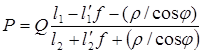 ,
, ,
, ,
,


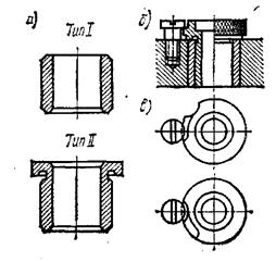
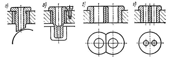
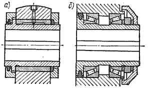
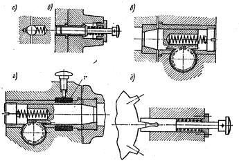
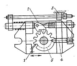


4.5 Tool housings
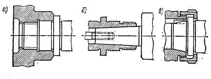

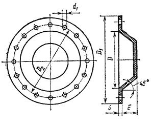
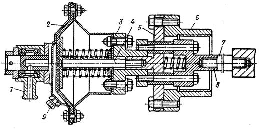
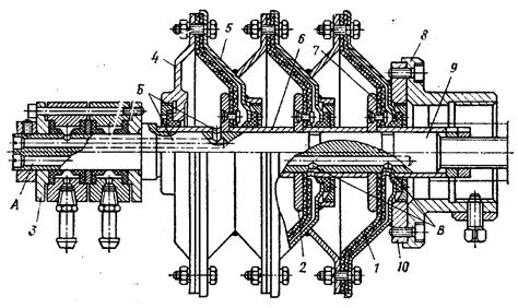
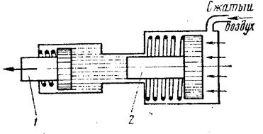
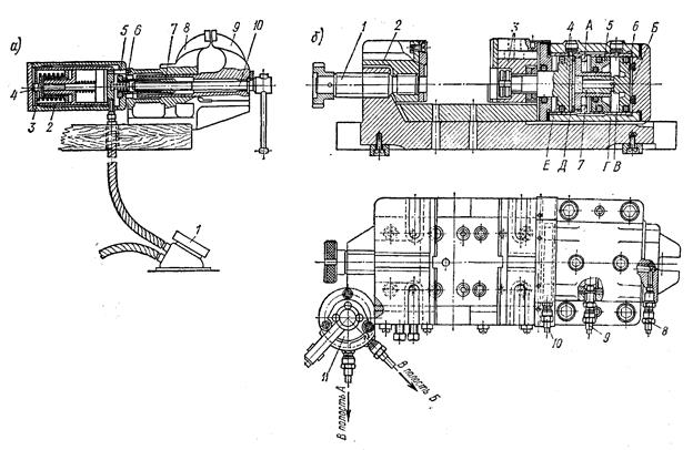
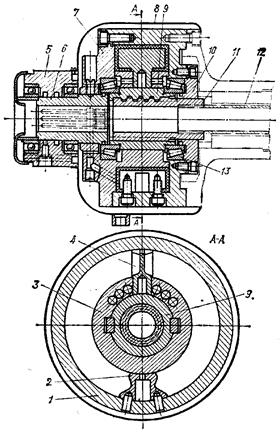
The USP system is successfully used at a number of single and serial production plants. USP kits are used for drilling, turning, milling, boring, gear shaping, grinding and other types of processing, as well as welding work and control operations. During machine work, with the help of USP, parts with sizes up to 2500 X 2500 X 1000 mm are processed. 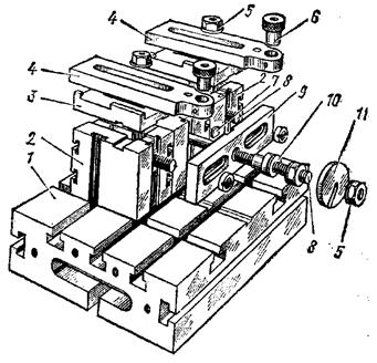
![]() ,
,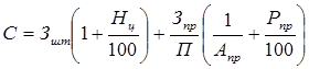 ,
,


How to cook ham in the oven at home
Pain in the lower abdomen during pregnancy, reasons for what to do Can the lower abdomen hurt if pregnant
Protein for muscle gain
The best vitamins for men according to customer reviews
How to lose weight on a vegan diet?