It happens that the bearing in the crankcase has turned, its seat in the engine block or in the crankcase of some unit (gearbox or rear axle) is weakened, and it is impossible to operate a car or motorcycle with such a malfunction, since the bearing seat will break even more. Such a malfunction can occur from repeated or incorrect installation of the bearing in the hole (socket) of the crankcase, lack of lubrication (the bearing wedges and it turns), or simply from inaccurate manufacturing of the bearing hole. And owners of any vehicle, or just some kind of machine or unit. How easy it is to get rid of such a malfunction at home, without having galvanizing equipment, even the simplest one (for zinc coating), we will consider in this article.
Of course, you can increase the diameter of the outer race of the bearing if you cover it with chromium, or a layer of zinc, and I already wrote about this (you can read it here). But for this you will need to make special plugs (so that the coating layer does not fall on the balls, separator and internal surfaces clips), and you have to tinker with chemicals.
In the same article, we will consider another, even simpler way to increase the outer diameter of the clip, which can be done both in his garage and in the field by any person, even a schoolboy.
First, let's look at the more common traditional methods restoring a broken mounting hole in a bearing, maybe one of the beginners does not know about them and they will come in handy for someone. And after that we will analyze a rarer method that most repairmen do not know about.
1 - crankcase, 2 - sleeve, 3 - outer race of the bearing.
So, if the bearing is mounted in the crankcase of some unit or its cover, and the mounting hole is broken, then the cover is fixed through the faceplate in a lathe, and the crankcase in a cardine boring machine, and the diameter of the mounting hole is bored by about 3 - 4 mm and after this, a repair sleeve is pressed into the bored place, in which inner diameter a little more (with an allowance for finishing) and after screwing, bore the inner diameter of the sleeve to the diameter of the outer race of the bearing (see Figure 1).
This method is quite common, despite the fact that many craftsmen have to look for a cardinal boring or lathe and also produce a fixture for precise fixing of the part. In addition, this method will not work if the thickness of the metal of the housing wall becomes thin after boring and does not provide sufficient rigidity to the bearing bore. And this stops many, and you can’t find a competent machine operator everywhere.
Some "masters" generally try to get by with just punching the landing surface, but it is hardly worth hoping that such a "repair" will last for a long time, usually for a couple of hours. After all, the bearing cage with this method will not lie on the entire surface of the mounting hole, but only on scanty areas (pimples), which have a scanty area. Yes, and the pinned places are quickly crushed already during the installation of the bearing (especially in a soft aluminum crankcase), and the bearing cage again begins to hang out and turn.
most accessible and effective ways repair, this is when the enlarged bearing hole is not touched at all, but only increases the thickness of the bearing race. And there are also several ways, this is the spraying of metal with special installations, which are still very rare, this is the coating of the clip with chrome, well, the coating of the clip with zinc, which is more accessible at home, which I already wrote about (link above in the text).
But there is another little-known, but very simple way to increase the size of any round metal part, and in this case, bearing races, which is not difficult to implement at home, in the garage and even when traveling (on the side of the road). Moreover, special qualifications or some kind of secret skill are not required, and any driver who is able to open the hood on his car will cope with this simple operation quite easily, especially if an assistant will help.
The principle of building up metal with this in a simple way, is based on the principle of resistance welding. And for work, we need only a couple of springs, for example, from Moskvich or the Volga, a couple of pieces of thick wire (cables with a crocodile clip, for lighting are suitable), and a well-charged battery, or a welding transformer (a powerful starter can also Charger).
1 - battery, 2 - springs, 3 - bearing, 4 - table with stands.
And in order to increase the diameter of the outer race of the bearing, this bearing will need to be rolled between two springs, connected to the springs electricity(See Figure 3). And as I said, springs from our domestic cars will do, but if the bearing is much larger, for example, from a truck, then the width of the springs needs to be chosen wider, from the same truck (you can find old springs at scrap metal collection points, or in car fleets) .
The length of the springs also depends on the diameter of the bearing, but as a rule, the length of one spring is about a meter, and the second can be cut to half a meter (it will be more convenient to work this way). We connect each spring with a cable to the pole pieces of the battery or transformer, ensuring good contact.
You can use the terminals from the car to tightly connect the cables to the battery, but you can clamp the cables to the springs using bolts with washers, or powerful alligator clips (such as welding). Moreover, the polarity when connecting the springs can be any.
a - surfacing thickness 0.1 mm, b - surfacing thickness 0.25 mm, c - surfacing thickness 0.5 mm.
Rolling is performed several times, and at the same time, the surface of the outer cage is gradually covered with a large number of small tubercles welded from the metal of the springs (see photo on the left). And it is enough to make several rollings, and the surface of the outer race of the bearing is already growing to such a diameter that the cage will no longer hang out in its broken hole.
It is useful to wear rubber gloves on the ends of the upper spring and tape them, or simply wrap them with electrical tape. This will avoid a short circuit of the springs and damage to the battery if the upper spring touches the lower spring with its end during rolling.
This often happens if the diameter of the bearing to be remanufactured is small. And if the bearing is already of a very small diameter, then it is useful when working on the contrary to deploy the upper spring with a deflection upwards.
When working with a battery, in order not to spoil it, it is useful not to protect rust on the springs at all, since rust has additional resistance that will prevent excessive current growth. But if you wish, you can also connect a rheostat, with which you can accurately select the desired current strength.
If a welding transformer is used instead of a battery, then of course it is better to use one that has a current adjustment. The welding current is set within 100 - 150 amperes, and the larger the current, the faster the metal will build up, but the deposited particles will also be larger.
Therefore, it is useful to choose golden mean so that the particles of the deposited metal (inclusions) are not large, and you don’t have to mess around for a long time. You can practice first on an unusable bearing. But as a rule of thumb, to normally increase the diameter of a 110mm bearing by 0.5mm would require 150 amps of current and about five minutes of knurling. And at the same time, the bearing heats up only up to 100 degrees, which means that the structure of its metal does not change.
 After knurling, as can be seen in the photographs, the surface of the clip has a somewhat rough appearance, which is even better, since it will never again rotate in its hole (the grip of a rough surface is better than a smooth one). But still, if someone wants to restore the surface of the outer clip in this way to the factory smooth state, then it is quite possible to make the coating twice as thick (instead of 0.5 mm, make 1 mm). And after that, give the bearing to the turner, who will polish the clip to a smooth state, removing about 0.5 mm from the surface.
In the method described in this article, the landing of the bearings that turned in their places was restored not only for cars and motorcycles, but also for trucks, and a lot of money was saved, since the crankcase or rear, hub, or engine block no longer needed to be changed, what I wish you too; Good luck everyone.
Seats often cannot be repaired and then the question arises of replacing the part associated with the bearing and having lost the nominal parameters of the seat. Such a repair option is quite economically impractical. The way out in this situation is to repair using Dimet technology.
Let's consider examples of repairing seats by the method of cold gas-dynamic spraying.
Motorcycle wheel bearing seat.
The defect of the seat is that the outer ring of the bearing rotates during operation, which gives additional loads on the axis of the inner ring and on the bearing itself.

Image 1. Seat for the outer ring of the bearing on the wheel of a motocross motorcycle.
To eliminate this problem, it is necessary to add a layer of metal to the inner diameter of the hub. The hub is made of aluminum alloy. Before applying the composition, we pre-treat the surface with an abrasive compound K-00-04-16. An additional layer is applied in the third mode of the Dimet-405 apparatus. Spraying is done with a margin. The final processing of the coating is carried out at a low cutter feed at high speeds.


Image 2. Stages of repair (a - aluminum layer applied with a margin, b - final version of the finished seat)
Crankshaft half ring seat
The seat of the remote half-ring of the crankshaft of the cast-iron Mercedes-Benz cylinder block was repaired using the Dimet technology. The final processing was carried out with a special cutter.


Hub bearing seat
The repair of the seat of the Ford cast-iron hub was carried out by applying an aluminum layer, 0.3 mm in size. These manipulations provided the necessary tightness in the connection.


Image 1. Stages of repair (a - initial, b - final)
Motor bearing seat
The repair of the bearing seats in the motor housing was carried out by the apparatus, aluminum composition, spraying mode - "3". The images show the stages of repair.
Choice proper fit, ensuring the required cleanliness and dimensional tolerances of surfaces for bearings is a key factor in ensuring the durability and reliability of mechanisms.
Proper fit is essential for bearing performance.
Based on the characteristics of the bearing, the ring that rotates must be fixed on the supporting surface motionless, with an interference fit, and the fixed ring should fit into the hole with a minimum clearance, relatively freely.
An interference fit of the rotating ring prevents it from turning, which could lead to wear of the supporting surface, contact corrosion, unbalance of the bearings, flaring of the support, excessive heat. So, basically, the bearing is mounted on a shaft that operates under load.
For a fixed ring, a small gap is even useful, and the possibility of turning no more than once a day makes the wear of the supporting surface more uniform and minimizes it.

Basic terms
Let us consider in more detail the basic terms and concepts that determine the fit of bearings. Modern mechanical engineering is based on the principle of interchangeability. Any part made according to one drawing must be installed in the mechanism, perform its functions, and be interchangeable.
To do this, the drawing determines not only the dimensions, but also the maximum, minimum deviations from them, that is, tolerances. Tolerance values are standardized unified system for tolerances, landings ESDP, broken down by degrees of accuracy (qualities), are given in tables.

They can also be found in the first volume of Anuryev's Handbook of Mechanical Engineer, and GOST 25346-89, as well as 25347-82 or 25348-82.
According to GOST 25346-89, 20 accuracy qualifications are defined, but in mechanical engineering they are usually used from 6 to 16. Moreover, the lower the qualification number, the higher the accuracy. For landings of ball and roller bearings, 6.7, less often 8 qualifications are relevant.

Within the same qualification, the size of the tolerance is the same. But the upper and lower deviations of the size from the nominal are located in different ways and their combinations on the shafts and holes form different landings.
There are landings that provide a guarantee of clearance, interference and transitional, realizing both the minimum clearance and the minimum interference. Landings are indicated in Latin lowercase letters for shafts, large for holes and a number indicating quality, that is, the degree of accuracy. Landing designations:
- with clearance a, b, c, d, e, f, g, h;
- transitional js, k, m, n;
- with interference p, r, s, t, u, x, z.
According to the hole system for all qualifications, it has a tolerance of H, and the nature of the fit is determined by the shaft tolerance. This solution allows you to reduce the number of required control gauges, cutting tools and is a priority. But in some cases, a shaft system is used, in which the shafts have a tolerance h, and the fit is achieved by machining the hole. And just such a case is the rotation of the outer ring of a ball bearing. An example of such a design can serve as rollers or tension drums for belt conveyors.

Selecting a fit for rolling bearings
Among the main parameters that determine the fit of bearings:
- the nature, direction, magnitude of the load acting on the bearing;
- bearing accuracy;
- rotational speed;
- rotation or immobility of the corresponding ring.
The key condition that determines the landing is the immobility or rotation of the ring. For the stationary ring, a close clearance fit is selected and gradual slow turning is considered a positive factor that reduces overall wear, preventing local wear. The rotating ring must be planted with a reliable tightness, excluding rotation in relation to the seating surface.
Next an important factor which the bearing fit on the shaft or in the bore must correspond to is the type of loading. There are three key types of loading:
- circulating during rotation of the ring relative to a radial load constantly acting in one direction;
- local for a fixed ring with respect to radial loading;
- oscillatory with a radial load oscillating relative to the position of the ring.

According to the degree of accuracy of the bearings in the order of their increase, they correspond to five classes 0,6,5,4,2. For mechanical engineering with loads of low and medium magnitude, for example for gearboxes, class 0 is common, which is not indicated in the designation of the bearings. For higher accuracy requirements, the sixth grade is used. At higher speeds 5.4 and only in exceptional cases the second. Sixth Grade Example 6-205.

In the process of actual design of machines, the fit of the bearing on the shaft and in the housing is selected in accordance with the operating conditions according to special tables. They are given in volume two of the Handbook of the designer-machine builder Vasily Ivanovich Anuriev.

For the local load type, the table suggests the following fits.

Under conditions of circulation loading, when the radial force acts on the entire raceway, the loading intensity is taken into account:
Pr=(k1xk2xk3xFr)/B, where:
k1 – dynamic overload coefficient;
k2 is the attenuation coefficient for a hollow shaft or a thin-walled housing;
k3 is the coefficient determined by the effect of axial forces;
Fr - radial force.
The value of the coefficient k1 with overloads less than one and a half times, small vibrations and shocks is taken equal to 1, and with a possible overload from one and a half to three times, strong vibrations, shocks k1=1.8.
The values of k2 and k3 are selected according to the table. Moreover, for k3, the ratio of the axial load to the radial load, expressed by the parameter Fc/Fr x ctgβ, is taken into account.

The bearing fits corresponding to the coefficients and the loading intensity parameter are given in the table.

Processing of seats and designation of landings for bearings in the drawings.
The seat for the bearing on the shaft and in the housing must have lead-in chamfers. The roughness of the seat is:
- for a shaft neck with a diameter of up to 80 mm for a class 0 bearing Ra=1.25, and for a diameter of 80…500 mm Ra=2.5;
- for a shaft neck with a diameter of up to 80 mm for a bearing of class 6.5 Ra=0.63 and for a diameter of 80…500 mm Ra=1.25;
- for a hole in the housing with a diameter of up to 80 mm for a class 0 bearing Ra = 1.25, and with a diameter of 80 ... 500 mm Ra = 2.5;
- for a hole in the housing with a diameter of up to 80 mm for a bearing of class 6,5,4 Ra = 0.63, and with a diameter of 80 ... 500 mm Ra = 1.25.
The drawing also indicates the deviation of the shape of the bearing seat, the end runout of the shoulders for their stop.
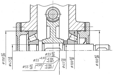
An example of a drawing showing the fit of the bearing on the shaft Ф 50 k6 and the shape deviations.

The values of form deviations are taken according to the table, depending on the diameter that the bearing has on the shaft or in the housing, the accuracy of the bearing.

The drawings indicate the diameter of the shaft and housing for fit, for example, F20k6, F52N7. On assembly drawings, you can simply indicate the size with a tolerance in the letter designation, but on the detail drawings, it is desirable, in addition to the letter designation of the tolerance, to give its numerical expression for the convenience of workers. The dimensions on the drawings are indicated in millimeters, and the tolerance value is in micrometers.
Restoration of seats for bearings using metal polymers by gluing.
The essence of this method lies in the fact that the process of restoring the seat is combined with the assembly operation of the bearing assembly. As a result, a fixed connection between the bearing and the shaft (bearing housing) is formed, which by many times exceeds in its strength characteristics the interference fit recommended in such cases, which more reliably prevents the bearing rings from turning, eliminating wear and providing more reliable performance node. At the same time, gluing, unlike an interference fit, does not lead to the appearance of stresses and deformations of the bearing rings, which also contributes to its more comfortable operation.
To dismantle the bearing assembly restored in this way, it is necessary to heat the metal-polymer layer formed at the place of gluing to a temperature above 300 0C or burn it out, for example, using a gas burner.
The main stages of the process of restoring seats using pasting.
I.Restoration of seats with insignificant (up to 0.25 ÷ 0.3 mm in diameter), uniform wear (without preliminary machining restored surface).
1. Prepare the surface to be restored in accordance with general recommendations(clean from dirt, oil, etc., roughen with sandpaper, degrease).
2. Wipe and degrease the bearing seat.
3. Carry out a control assembly: the bearing should be installed on the seat quite easily, without significant effort.
4. Protect the bearing separator with adhesive tape or electrical tape from possible ingress of metal polymer into it during gluing.
5. Prepare the required dose of metal polymer.
6. Apply the necessary layer or layers of metal polymer to the seat of the shaft (housing), thoroughly wetting the surface to be restored.
7. Lubricate, literally wetting, with a thin layer of metal polymer the bearing seat.
8. Install the bearing on the shaft (in the housing), carefully pressing it against the restrictive collars, bushings, circlips.
9. Remove the squeezed-out excess metal polymer, clean unprotected places on the shaft (in the housing) with acetone if metal polymer accidentally gets on them, remove the protection from the separator.
10. After polymerization of the metal polymer, the unit is ready for further operation.
Note:
With the indicated wear values, the centering of the bearing relative to the shaft (housing) during gluing is ensured both by the particles of the metal polymer filler falling into the gap, and by additional methods, for example: etc.
2. Restoration of seats with minor (up to 0.1 ÷ 0.15 mm in diameter) wear.
When restoring by gluing the seats of shafts (housings) with a wear value of less than 0.1 ÷ 0.15 mm in diameter (the size of the gap is commensurate with the size of the filler particles), it is necessary to pre-boring the seat by 0.5 ÷ 1.0 mm, with cutting "torn threads" or grooves. To ensure bearing centering during gluing, boring is carried out leaving bands along the edges of the seat and along its length (the total width of the bands should not exceed 50% of the entire gluing surface) - see Figure 1.
font-size:11.0pt;font-family:Arial">Fig. 1. Restoration of the seat on the shaft using metal polymers by gluing the bearing:
D no. - d 1 = 0.1 ÷ 0.15 mm;
D 1 - d 2 \u003d 0.5 ÷ 1.0 mm;
I - places for cutting “torn threads” or annular grooves.
The remaining recovery steps are similar to the operations in paragraph 1.
3. Restoration of seats with significant (over 0.5 ÷ 1.0 mm in diameter) and uneven wear.
When restoring by gluing seats with significant and uneven wear, the issues of centering and ensuring the alignment of the bearing and shaft (bearing housing) are of particular importance. These problems can be solved in the following ways.
1. On the worn surface along the forming lines, metal gaskets of various thicknesses are installed (approximately 0.05 ÷ 0.08 mm thinner than the wear in this place) in the form of narrow metal strips that are longer than the wear site. The free ends of these strips are fixed with adhesive tape, thread, etc. near the place of gluing (preferably on the section of the shaft with a smaller diameter). The control installation of the bearing is carried out (the bearing should be installed on the seat quite easily, without significant effort). After that, a metal polymer is applied to the place of wear (the places under the gaskets are also coated). The bearing is installed. After the polymerization of the metal polymer, the incoming ends of the gaskets are cut off.
2. On the places of wear along the diameter by welding, small point(to avoid overheating of the shaft) sagging in the form of rings. After that, they are turned to the nominal bore diameter of the bearing. The bearing is being tested. After that, the insert is made according to the schemes described above.
3. On worn surfaces, a groove is made to install two or more centering rings. Rings (split) are fixed in the prepared grooves by welding or gluing using a metal polymer. Installed rings are machined to the nominal bore diameter of the bearing. Further, the insert is made according to the schemes described above.
Other methods of centering the bearing can be used in the process of restoring the seat by gluing using metal polymers.
Attention!
When restoring by gluing seats for bearings, before applying the metal polymer, it is necessary to protect the existing oil channels with adhesive tape, adhesive tape.
Landings
The importance of a proper fit
If a rolling bearing with an inner ring is fitted onto the shaft only with an interference fit, dangerous annular sliding can occur between the inner ring and the shaft. This sliding of the inner ring, referred to as "slippage", causes the ring to slip annularly against the shaft if the interference fit is not tight enough. When slippage occurs, the fitted surfaces become rough, causing wear and significant damage to the shaft. Abnormal heating and vibration can also be caused by abrasive metal particles penetrating the inside of the bearing.
It is important to prevent slippage by securely fastening with sufficient interference the ring that rotates, either to the shaft or in the housing. Slip cannot always be eliminated by axial tightening through the outer surface of the bearing ring. however, it is generally not necessary to preload rings subjected to only static loads. Fitting is sometimes done without any tightness on either the inner or outer ring to accommodate specific operating conditions, or to facilitate installation and disassembly. In this case, lubrication or other applicable methods should be considered to prevent damage to the fitting surfaces due to slippage.
Loading and landing conditions
| Load Application | Bearing performance | Load conditions | Landing | ||
| inner ring | outer ring | inner ring | outer ring | ||
| rotational | static | Rotational load on inner ring, static load on outer ring | Interference landing | Loose fit | |
 |
static | rotational | |||
 |
static | rotational | Rotational load on outer ring, static load on inner ring | Loose fit | Interference landing |
 |
rotational | static | |||
| Load direction not detected due to direction change or unbalanced load | Rotational or static | Rotational or static | Interference landing | Interference landing | |
Fits between radial bearings and housing bores
| Load conditions | Examples | Tolerances for housing openings | Axial displacement of the outer ring | Notes | ||
| One-Piece Enclosures | Large bearing loads in thin-walled housings or heavy impact loads | Automobile wheel hubs (roller bearings), crane, working wheels | R7 | Impossible | - | |
| Car wash wheel hubs (ball bearings), vibration screens | N7 | |||||
| Light or fluctuating loads | Conveyor rollers, rope pulleys, idler pulleys | M7 | ||||
| Load direction not defined | Heavy shock loads | Traction motors | ||||
| One-piece or split housings | Normal or heavy loads | Pumps, crankshafts, main bearings, medium and large motors | K7 | Usually not possible | If axial displacement of the outer ring is not required | |
| Normal or light loads | JS7 (J7) | Maybe | Axial displacement of the outer ring is required | |||
| Loads of all kinds | General application of bearings, railway axleboxes | H7 | Easy possible | - | ||
| Normal or high loads | Insert bearings | H8 | ||||
| Significant rise in temperature of the inner ring in the shaft | Paper dryers | G7 | ||||
| One-Piece Enclosures | Precise operation desirable under normal or light loads | Grinding spindle rear ball bearings, high speed centrifugal compressor swivel bearings | JS6 (J6) | Maybe | For larger loads, a tighter fit than K is used. When high accuracy is required, very close tolerances should be used for the fit. | |
| Load direction not defined | Grinding spindle front ball bearings, fixed bearings (mounts) of high-speed centrifugal compressor | K6 | Usually not possible | |||
| Desirable precise functioning and high rigidity under fluctuating loads | Cylindrical roller bearings for machine tool spindle | M6 or N6 | Impossible | |||
| Minimum noise level required | Appliances | H6 | Easy possible | - | ||
Table notes:
- This table applies to cast iron and steel housings. For housings made of light alloys, the fit should be tighter than in this table.
- Not applicable for special landings.
Fits between radial bearings and shafts
| Load conditions | Examples | Shaft diameter, mm | Shaft tolerance | Notes | |||
| ball bearings | Cylindrical and tapered roller bearings | Spherical roller bearings | |||||
| RADIAL BEARINGS WITH CYLINDRICAL BORE | |||||||
| Slight axial displacement of the inner ring on the shaft is desirable | Wheels on static axles | All shaft diameters | g6 | Using g5 and h5 where precision is required. In case of large bearings, f6 can be used for light axial movement | |||
| Slight axial displacement of the inner ring on the shaft is not required | Idler pulleys, rope pulleys | h6 | |||||
| Rotational load on the inner ring or indeterminate load direction | Electrical household appliances, pumps, fans, vehicles, precision machine tools, metal cutting machines | <18 | - | - | js5 | - | |
| 18-100 | <40 | - | js6 (j6) | ||||
| 100-200 | 40-140 | - | k6 | ||||
| - | 140-200 | - | m6 | ||||
| Normal loads | General bearing applications, medium and large motors, turbines, pumps, engine main bearings, gearboxes, woodworking machines | <18 | - | - | js5 (j5-6) | k5 and m6 can be used for single row tapered roller bearings and single row angular contact bearings instead of k5 and m5 | |
| 18-100 | <40 | <40 | k5-6 | ||||
| 100-140 | 40-100 | 40-65 | m5-6 | ||||
| 140-200 | 100-140 | 65-100 | m6 | ||||
| 200-280 | 140-200 | 100-140 | n6 | ||||
| - | 200-400 | 140-280 | p6 | ||||
| - | - | 280-500 | r6 | ||||
| - | - | over 500 | r7 | ||||
| High loads or shock loads | Railway axle bushings, industrial vehicles, traction motors, structures, equipment, crushing plants | - | 50-140 | 50-100 | n6 | Bearing internal clearance must be greater than CN | |
| - | 140-200 | 100-140 | p6 | ||||
| - | over 200 | 140-200 | r6 | ||||
| - | - | 200-500 | r7 | ||||
| Axial loads only | All shaft diameters | js6 (j6) | - | ||||
| RADIAL BEARINGS WITH TAPERED BORES AND BUSHINGS | |||||||
| All types of loads | General application of bearings, railway axle boxes | All shaft diameters | H9/IT5 | IT5 and IT7 mean that the deviation of the shaft from its true geometric shape, for example round or cylindrical, must be within tolerances IT5 and IT7 respectively | |||
| Transmission shafts, woodworking machine spindles | H10/IT7 | ||||||
Note: This table only applies to solid steel shafts.


Chocolate biscuit: the secrets of cooking in a slow cooker and oven
Chemical composition and nutritional value
Apple chips at home
Braised cabbage with white beans, recipe
How to reduce the ass, hips and stomach at home?