Screw compressor device
This article will focus on the design of screw compressors, the interest in which has grown significantly in recent years. This is understandable. A screw compressor has a number of advantages compared to piston or centrifugal compressors, which were traditionally used earlier at Russian factories.Let us once again briefly recall the main advantages of screw compressors:
- high reliability;
- long service life;
- the possibility of continuous round-the-clock operation;
- ease of installation and connection;
- relatively low operating costs;
- system availability automatic control;
- low noise level;
- high purity of the resulting compressed air;
- low level of energy consumption per cubic meter. meter of produced air.
How does a screw compressor work?
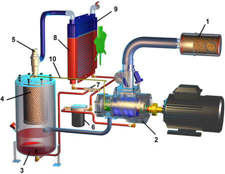
Consider the most common layout option shown in Fig. 12.Rice. 1.2 Screw compressor device

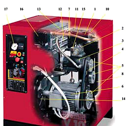
Air through the suction valve (2) and the air filter (1) enters the screw pair (3), which is the "heart" of the compressor. Here it is mixed with oil circulating in a closed circuit, and the resulting air-oil mixture is injected into the pneumatic system using a screw block. Separation of oil and air takes place in the separator (8.9). The oil-free air through the cooling radiator (13) enters the compressor outlet, and the oil returns to the screw pair. Depending on the temperature, it passes either in a small circle, or in a large one, through the oil cooler (12). Adjustment is carried out using a thermostat (11). The screw pair is driven by an electric motor (6), and automatic switch on and shutdown of the compressor is carried out using the pressure switch (16).
Now let's take a closer look at constituent parts compressor, their purpose and device.
The basis of a screw compressor is a screw group, its design is clearly visible in Fig.3.
Rice. 3 Screw block in section
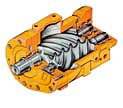
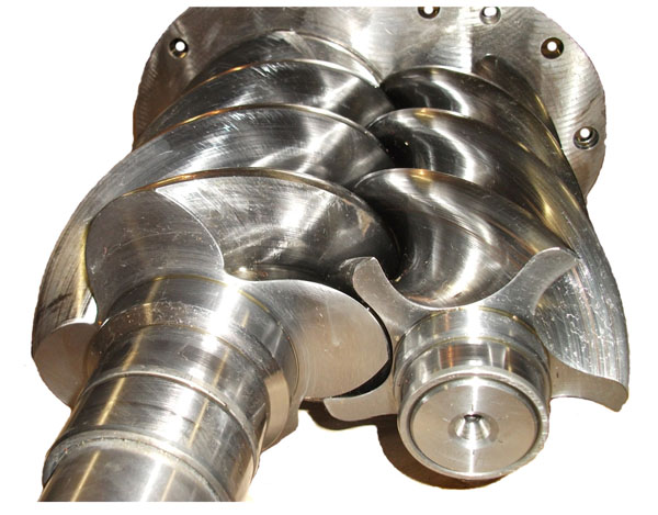
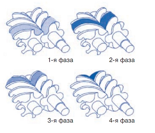
The working element of the screw group is a screw pair consisting of two interlocked "worm" rotors. Usually, the leading rotor is made as a screw with four threads (coils), and the driven one with six (Fig. 4).
Rice. 4 Scheme of operation of the screw block
Such a gear ratio is considered optimal and is done in order to reduce the load on the drive screw. The compression volume is formed between the turns of the screw group and the body (highlighted by a bold line). A full working cycle of compression is carried out in one revolution of the lead screw. From all that has been said, it follows that this design can only work if all parts of the working element (body and two mutually fitted rotors) are very precisely executed.
Such a device is fundamentally different from a reciprocating compressor, which is characterized by the reciprocating movement of the piston in the cylinder, leading to increased heating and strong vibrations. That is why the use of industrial reciprocating compressors requires laying a massive foundation to compensate for vibrations and the use of water cooling, that is, the organization of a circulating water supply system with bulky cooling towers.
Of particular note is the role of oil in a screw compressor, which performs several functions at once:
- creating an oil film and providing a gap between the rotors of the screw group;
- air transportation;
- lubrication of the bearings of the working element;
- heat dissipation.
To ensure temperature control, the oil circulating in the compressor is pumped through a cooling radiator (12). The fact is that at very high temperatures, above 110 ° C, it loses its density, and this threatens to jam the rotors of the screw pair. At the same time, at low temperatures, the oil has an excessive viscosity, and, in addition, a cold air-oil mixture can lead to the formation of condensate, which degrades the air quality at the compressor outlet. A thermostat (11) is used to ensure that the oil temperature reaches the operating temperature as quickly as possible. That is, there is a small circle of oil circulation when it, bypassing the radiator, returns to the system. As it heats up, a large circle of circulation through the radiator is turned on. The thermostat opens when the oil temperature reaches about 70°C. The air-oil radiator (12.13) is a two-section, combined one. In addition to cooling the oil, it also serves to cool the air. As a result, the difference between the temperature environment and air temperature at the compressor outlet does not exceed 7°C. This allows for further efficient work dryer and the entire air preparation system.
The radiator is cooled by the air flow passing through it, which is forced into the compressor by a fan (14) mounted on the motor shaft (6). All compressor panels must be closed during operation, this is how the most efficient direction of air movement is set, ensuring the removal of heat generated during compression. It is possible to reuse the heated air, for example, for space heating in winter. It follows from the above that the screw pair can only work if it is constantly in the air-oil mixture.
The resulting problem of separating air from oil is solved with the help of the following elements
- oil collecting receiver (8);
- oil separator filter (9);
- oil return device.
The oil separation system has three stages of cleaning, which ensures its maximum efficiency. As a result, the residual oil content in compressed air does not exceed 3 mg/cu. m. At the first stage, separation occurs due to centrifugal forces and gravity. The air-oil mixture comes from the screw group through the connecting hose to the oil separator receiver (8). Hitting the walls of the vessel, heavier oil particles under the influence of gravity and centrifugal forces sink to the bottom. For the second stage of mechanical cleaning, a dividing wall is used, located in the middle of the receiver above the inlet. The air-oil mixture, rising, passes through the holes in the partition, on which oil particles also settle. The final element of the internal cleaning is the oil separator filter (9), which is a conventional ceramic filter element. The oil that is retained by the filter accumulates in a special recess and returns to the screw block through the connecting tube. For visual control of oil return to the system, a cylindrical thickening (19) was made on the transparent tube (Fig. 5. The importance of this element lies in the fact that it allows you to check the efficiency of the oil separator, which decreases as the amount of oil increases.
The oil sump receiver (8) is equipped with safety valve(10), which protects it from overpressure.
The oil is cleaned from contamination by means of an oil filter (7). It prevents solid particles from entering the working surfaces of screws and bearings.
Let's move on to consideration of other functional elements of the compressor (Fig. 5).
Rice. 5 Functional diagram of a screw compressor
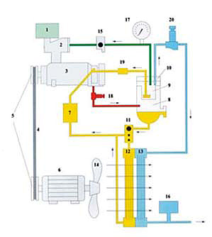
The air filter (1) installed at the compressor inlet is designed to clean the incoming air. It protects the screw pair from the ingress of foreign particles and thus ensures the reliability and durability of the compressor. Premature clogging of the air filter can cause the motor to overheat and activate the emergency stop system. The suction valve (2) serves to prevent compressed air and oil from being blown out when the compressor stops. In fact, this is a conventional spring-loaded pneumatic valve that is constantly open when air is drawn in. The operation of the suction valve is controlled by a pneumoautomatic device - an electro-pneumatic idle valve (15). The task of this device is to reduce the pressure inside the compressor to 2.5 bar before the motor stops. This avoids oil surges caused by the inertia of the suction valve and unpleasant water hammer that occurs when the compressor suddenly stops. The valve opens a channel connecting the area of the oil separator filter with the suction area of the screw pair through the orifice. The effective orifice section is adjusted at the factory so that the pressure in the area of the suction valve drops to 2.5 bar within a given time. With this residual pressure in the system, the suction valve has time to close and the drive motor can be switched off.
Another device that ensures the operation of the compressor in idling mode is the minimum pressure valve (20). It is closed as long as the pressure inside the compressor remains within 4-5 bar (hence the name). At the same time, it acts as a check valve, separating the compressor from the pneumatic line when it is stopped or idling.
The pressure switch (16) ensures automatic operation of the compressor. When the pressure in the network reaches a predetermined maximum value (for example, 10 bar), it sends a signal to the idle valve, which operates and switches the compressor to idle. When the pressure drops to the minimum (for example, 8 bar), the idling valve is closed by a signal from the relay, and the compressor starts again to pump air into the pneumatic line. If the compressor has already switched to standby mode, then a signal is given to start the electric motor.
The screw group is driven by an electric motor (6) through a belt drive (4). The gear ratio, and, consequently, the speed of rotation of the screw block is set by the dimensions of the pulleys (5). The higher the maximum pressure of the compressor, the lower the possible rotation speed of the screw group, the lower the compressor capacity.
The emergency protection system consists of two independent devices.
The thermal protection sensor is installed on the electric motor. When the limit values of the consumed current are reached, the relay is activated and the engine is disconnected from the network.
Another sensor is installed in the screw pair in the area of the outlet pipe (18). The signal from the temperature sensor is fed to the input of the analog-to-digital converter and output to the display device. If the temperature at the outlet of the screw pair exceeds 105°C, the protection is activated and the engine is switched off.
The operation of a screw compressor can be conditionally divided into the following modes:
Start mode.
Necessary to minimize the load on the network at the time of compressor start-up. After pressing the "START" button, the electric motor is switched on according to the "star" scheme, which ensures the minimum load on the network at the time of switching on and starts the timer (2 seconds). After the set time (2 seconds), at the command from the timer, the engine switches to the operating mode, i.e. to the triangle pattern.Work mode.
In this mode, the pressure in the system begins to increase. The pressure gauge (17) located on the front panel shows the pressure inside the compressor, that is, in the area between the suction valve and the minimum pressure valve. The pressure in the line can be controlled by the pressure gauge located on the receiver. When first turned on, the pressure inside the compressor and in the line is almost the same. When the maximum pressure is reached, for example 10 bar, the pressure switch is activated and the compressor switches from operating mode to idle mode.idle mode.
Unlike a piston compressor, a screw compressor can operate in idle mode, the duration of which is set by a timer. In this mode, the compressor motor and screw group rotate, driving air through the internal circuit of the compressor, thus ensuring its effective cooling. The idle mode is transient and is used to put the system into standby mode or completely turn off STOP.On command from the pressure switch, the pneumoelectric idling valve is turned on, and the time relay is started (set, for example, for 4 minutes). The idle air valve opens the bypass between the suction valve and the oil separator filter. From this point on, the pressure in the line differs from the pressure inside the compressor, i.e. in the area between the suction valve and the minimum pressure valve, it begins to fall. The opening of the bypass channel is adjusted by the manufacturer in such a way that in a set time (4 minutes) the pressure drops to a minimum value of 2.5 bar. In this case, the engine shutdown occurs painlessly without oil ejection through the suction valve into the air filter area. After the set time (4 minutes) has elapsed, the electric motor is switched off by a command from the time relay and the system goes into standby mode. If the pressure in the line drops to the minimum (for example, 8 bar) before the time switch is triggered, the compressor switches back to operating mode.
Standby mode.
This mode lasts until the pressure in the working line becomes less than the minimum (8 bar). The system can be in standby mode for an arbitrary time, which depends on the air flow in the system. When the pressure in the system drops below the minimum, the pressure switch is activated, and the system again switches to the starting, and then to the operating mode. The pressure inside the compressor quickly reaches the value of the pressure in the line, its further growth occurs synchronously before switching to idle mode.STOP mode
The "STOP" mode is used for regular shutdown of the system. If the system was in operating mode at the time the STOP button was pressed, it is forced into idle mode and then turned off."ALARM-STOP" mode
The system can be switched to this mode by pressing the emergency shutdown button located on the control panel. It is used in case of urgent need to turn off the electric motor. On this command, the electric motor is switched off without switching to idle mode.As we can see, there is nothing complicated in the device of a screw compressor. At the same time, its design is reliable and designed for long-term trouble-free operation. In this article, we have considered only one of the most common and frequently encountered options. It gives a fairly complete picture of the operation of the compressor, however, it should be borne in mind that each manufacturer may make additional changes and additions to the design of their product. Of course, the reliability and service life of the compressor depends on many factors: compliance with operating conditions, timely execution of routine maintenance work, and, most importantly, the quality of all components and, first of all, the screw block, which is the most precise and expensive element of the system. We recommend buying equipment only known for a long time present on the market. Russian market companies that have their representation and service center here. Only in this case you can forget about the problems associated with providing air to your enterprise for a long time.
Recently, there has been a significant increase in interest in the use of screw compressors in the production. And there is nothing strange in this, because the screw compressor has undeniable advantages over other types of compressors - piston and centrifugal, which were previously used in all industries, and even now they still work in the old fashioned way at most Russian factories.
The main advantages of screw compressors are:
- increased work resource
- ease of installation and maintenance
- lower noise level
- high reliability
- possibility of continuous operation
- relatively low operating costs
- an automatic compressor control system is provided
- economical mode of operation, in terms of m3 of produced air
- resulting high purity compressed air
The device and principle of operation of a screw compressor is quite simple.
Air filter (1) through which atmospheric air, is cleaned in it, and through the suction regulator enters the screw block (2).
The most important and, accordingly, expensive part of any screw compressor is the screw block. Air is compressed directly in it, to the pressure necessary for specific purposes. This is due to the fact that open cavities, reciprocally engaged with teeth, rotating in opposite directions of the driving and driven worm rotors and the body of the screw block itself form a volume. It is in this volume, due to the vacuum that has arisen in it, air enters. Due to the rotation of the rotors, open cavities are closed, the volume between them decreases, and, as a result, the discharge pressure increases. At this point, to prevent unwanted contact between the metal surfaces of the rotors, as well as lubricate the bearings and remove the heat generated during the compression process, a carefully calculated, dosed oil injection is performed. Further, the resulting air-oil mixture enters the separator tank (3). Then, when passing through the air-oil separator (4), it is separated into oil and air.
The compressed air filtered from oil passes through the air cooler (9) and enters the compressor outlet.
The oil separated in the separator passes through the thermostat (7) and then enters the oil cooler (8). Then, in the oil filter (6), it is cleaned of all kinds of solid particles and again enters the screw block (2).
The screw block is driven by an electric motor. To ensure the cooling air flow inside the compressor, a fan is mounted on the motor shaft. Also, in some models of screw compressors, separate fans with their own electric motors are installed. The minimum pressure valve (5) ensures that the screw compressor operates in idling mode. It simultaneously acts as a check valve, thereby blocking the compressor from the pneumatic line.
Such an implementation is fundamentally different from the device of a reciprocating compressor, which is based on reciprocating movements of the piston in the cylinder, which results in increased vibration of the compressor and strong heating. As a result, when reciprocating compressors are used in industry, it becomes necessary to lay a powerful foundation that will be able to compensate for the resulting vibrations. Also, you need to use water cooling, for the arrangement of which you will need a bulky system of circulating water supply.

The role of oil in a screw compressor that performs several functions at once should be mentioned separately. Its main functions:
- the formation of an oil film, which provides the necessary clearance between the rotor and the screw group
- air transport
- lubrication of bearings of working elements
- cooling by heat dissipation
The screw compressor is designed to reduce pressure using rotors. They belong to rotary compressor devices. Despite the fact that the equipment appeared in the mid-30s, it is currently one of the most popular. Its main advantages are small dimensions, automatic operation, economy, etc. When installing it, a special foundation is not used, since the vibration level is low compared to other models. The air screw compressor has replaced other types of machines.  It is capable of up to 15 atmospheres. At the same time, the productivity reaches 100 m³ / min.
Advantages
Compared with other devices, the screw compressor has several advantages:
- Low which directly affects the quality of the supplied air. It is used in purified form for various pneumatic equipment. Moreover, installation of additional filters is not required.
- Low and vibration. As mentioned earlier, thanks to small size installation is carried out without a special sound-absorbing foundation. This feature helps to equip various portable devices with air.
- The screw compressor is air-cooled. It helps not only to cool different elements, but also to heat the premises due to the recycled heat.
- The ability of automatic operation, ease of installation and operation. The equipment is controlled by special automatic systems.
Flaws
Among negative sides can highlight the high cost and complexity of the design. In addition, the device requires additional equipment for the removal of hot air, which is necessary for heating the room. It is forbidden to use screw compressors in an environment with aggressive gases.
Screw compressor device
The simplest equipment has the following elements:
- A filter that serves to purify the air that enters the working element. As a rule, it consists of two parts. The first is installed on the body, the second is in front of the valve.
- suction valve. When the compressor stops, it serves to ensure that oil and air are not removed from the unit. It is controlled by pneumatics. By appearance is no different from a conventional spring valve.
- The main part is a screw block. Here are two connected rotors made of high quality steel. The cost of such an element is quite high. Its design provides for a thermal protection controller, which serves to stop the operation of the engine when the temperature reaches 105º degrees.
- Drive unit. It consists of two pulleys installed in the motor and rotor, serves to increase or decrease the speed of rotation. The higher it is, the more air will be compressed. However, the working pressure is reduced.
- The rotor speed depends on the pulleys.
- Motor. Rotational movements are carried out by a belt drive. It is equipped with a thermal protection sensor that turns off the engine when high temperatures are reached. In addition, it prevents the occurrence of various emergency situations.
- Oil filter. Purifies oil for screw compressors before it enters the engine.
- Oil separator. Serves to separate air from oil due to centrifugal force.
- Oil separator filter. Cleans the grease after separation from the air.
- It is triggered when the pressure in the oil separator exceeds the allowable limits.
- Thermostat. Regulates the temperature of the oil composition.
- Oil cooler. After separation from the air, the oil enters a special container, where it is cooled.
- Air cooler. To supply air in the room, reduce its temperature to 20º degrees.
- A fan is used to pump the above component.
- Relay. Provides automatic operation of the unit, performs the function of an electronic control system.
- A manometer is installed to control the pressure inside the unit.
- Minimum pressure valve. It is in the closed position until the pressure exceeds 4 bar.
The screw compressor is placed in the case. It is made from high quality steel.  Its surface is treated with a special substance that is not exposed to oil and other substances.
Screw compressor: principle of operation
Air from the atmosphere enters through the valve into the rotary mechanism, before being cleaned in the filter. Next comes the mixing with oil. Then it enters a special container for compression, while performing the following purposes:
- eliminates gaps between the screws and the case, so that the occurrence of leaks is minimized;
- makes sure that both rotors do not touch each other;
- removes the heat generated during the compression process.
The compressed mixture enters the oil separator, where it is separated into components.  The separated oil is cleaned in the filter and returned to the block, if necessary, it is cooled. Air also enters the air cooler and then is supplied from the compressor.
What operating modes are there?
A screw compressor, the principle of operation of which is described in the previous paragraph, can operate in the following modes:
- start. In this mode, the screw compressor is started and connected to the power grid according to the "star" scheme. After a few seconds, he switches to the "triangle" pattern.
- Work mode. The pressure in the compressor begins to rise. When a certain mark is reached, the idling of the unit is switched on.
- Idling. In this mode, the rotor rotates, during which the gaseous medium necessary for cooling the air moves. It allows the compressor to be put into standby mode before turning off the unit.
- Standby mode. The screw compressor will perform this function until the pressure indicator drops to the minimum value.
- stop. When this mode is enabled, the compressor equipment goes to idle, and then completely turns off.
- alarm-stop. It is used when it is necessary to urgently disable an air screw compressor.
Device repair
With good maintenance, the element can function for more than 50 thousand hours. Like any device, screw compressors need to be repaired over time. This equipment contains complex mechanisms and various configurations. 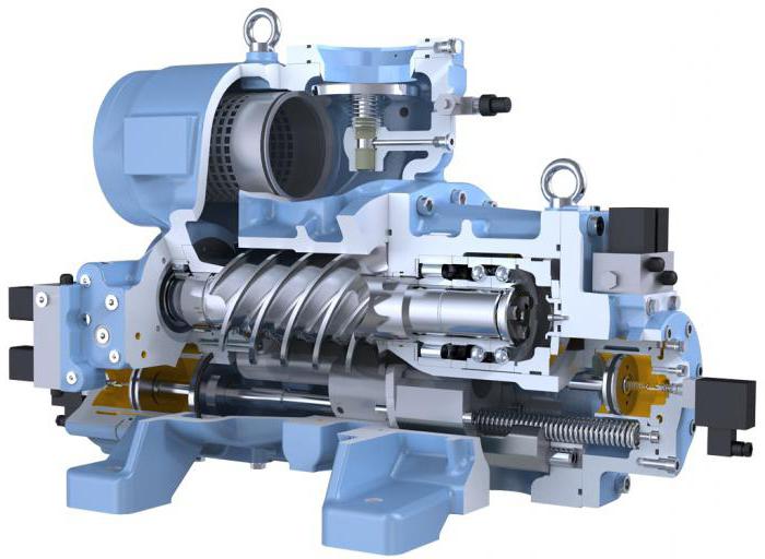 Quite often, electronics fail in such a device. have complex electronic systems which may burn out. Therefore, it is necessary to repair it, and in more difficult cases- replacement. This can be done by highly qualified professionals. The cost of the control unit is quite high. If there is a dryer in it, the repair of screw compressors will be even more expensive, since the equipment is a complex mechanism.
Price
As mentioned earlier, screw compressors are on the market in a very wide range.  The cost depends on the capacity of the equipment, as well as specifications. Its price range ranges from 250 to 700 thousand rubles.
In this article, I will talk about some key points about screw compressors.
I will also answer the following questions:
- Screw compressor - what is this mechanism?
- What is the design (or device) of a screw compressor?
- What is the working principle of a screw compressor?
Screw compressor - what is this "Beast"?
Screw compressors belong to the class of volumetric compressors. Those. compression of air or other gas occurs due to a change in volume. This type of compressor also includes reciprocating, diaphragm compressors, blowers, etc.
If to speak in simple words, then a screw compressor is a device that converts electricity through an electric motor into air / gas energy.
Compressed air/gas is one of the most common energy carriers. Compressed air/gas actuates various valves, pneumatic cylinders and other actuators.
When was the screw compressor invented?
A patent for the invention of the screw compressor was issued in 1934 to the Swedish engineer Eliot Lysholm. Since then, the design of the compressor has been repeatedly changed and improved in order to improve its performance. But the principle itself remained unchanged.
Scheme of a screw oil-filled compressor.
Schematically, the device of a screw oil-filled compressor is shown in the figure below.
Blue indicates the direction of air flow inside the compressor.
The yellow color indicates the oil flow inside the compressor.
The numbers in the figure indicate the main components of the screw compressor:
1 - air filter 10 - drain cock
2 - suction valve 11 - oil filter
3 - screw block 12 - thermostat
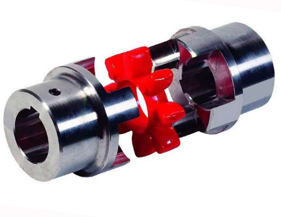
4 - drive clutch 13 - oil cooler
5 - electric motor 14 - air cooler
6 - minimum pressure valve 15 - fan
7 - separator 16 - temperature sensor
8 - unloading valve 17 - pressure sensor
9 - oil tank 18 - shut-off valve
When describing the principle of operation of a screw compressor, it is customary to separate the concepts "air flow" and " oil circuit».
Let's consider them in more detail.
Air flow.
When the compressor is running, atmospheric air through the filter1 and suction valve2 enters the screw block3 , in which air is compressed by rotating rotors (screws).
The screw block is the "heart" of the compressor. The reliability and durability of the entire compressor depends on the quality of its manufacture.
As a rule, the engine life of the screw block is up to overhaul is 36,000 - 40,000 hours. Overhaul consists in replacing bearings, shaft seals and setting clearances inside the screw block.
In our practice, there were screw compressors that worked for more than 70,000 hours without major repairs. But this is most likely an exception to the rule.
The principle of air compression in the screw block is clearly shown in the figure:
Air enters the compression cavity, which is formed by two screws and a screw block housing. When the screw block rotates, the cavity "moves" and decreases in volume. Thus, air or other gas is compressed.
The rotation of the rotors is provided by a drive consisting of an electric motor 5 and drive clutch 4 (in some models of compressors, a belt drive or gear drive is used instead of a clutch).
The presence of a suction valve 2 distinguishes screw compressors from reciprocating compressors. It allows the compressor to be in two operating modes during the rotation of the rotors - (the valve is open, compressed air is supplied to the consumer) and "idling"(the valve is closed, there is no compressed air supply to the consumer).
The idle mode plays a significant role in improving the reliability of screw compressors. It reduces the number of motor starts. Frequent engine starts are “stressful” both for the engine itself and for the power supply system of the enterprise.
As a rule, the suction valve is installed directly on the neck of the screw block:
A mixture of compressed air and compressor oil enters the oil reservoir 9 where the primary separation of compressed air from oil takes place.
The role of oil is very important for screw compressor operation. It removes the heat generated by compressing the air in the screw block. In addition, the oil forms a film around the rotating screws, sealing the "working chambers". The oil also prevents the screws from touching and mechanical wear.
Residual oil is removed from the compressed air in a separator 7 . Depending on the capacity of the compressor, the separator can be mounted separately from the oil reservoir 9 , or be inside it:
Further compressed air through the minimum pressure valve 6 enters the air cooler 14 , in which it is cooled by an air flow created by a rotating fan 15 .
The fan capacity is calculated so that the temperature of the compressed air at the compressor outlet does not exceed the ambient temperature by more than 10 °C.
Photo of the fan and heatsink on top of the compressor.
It should be noted that screw compressors with air or water cooling are used. Separately, I will talk about the pros and cons of the type of cooling in a separate article in the "Helpful Tips" section.
The photo below shows the air cooling system:
Minimum pressure valve 6 is a so-called non-return (or non-return) valve, equipped with a spring of a strictly defined stiffness. It plays a dual role:
- does not allow compressed air from the pneumatic network of the enterprise to penetrate back into the compressor when it is stopped;
- due to the presence of a spring, the pressure in the oil reservoir 9 when the compressor is operating on an “empty” pneumatic network, it is maintained at the level necessary for normal oil circulation - about 4.5 bar.
Compressed air is supplied to the consumer through a shut-off valve 18 .
Oil contour.
Oil separated from compressed air in an oil reservoir 9, is under pressure. Minimum pressure valve 6 maintains this pressure at a level of about 4.5 bar when operating in the "load" mode.
Depending on the temperature, the oil can circulate either only through the “small” circuit (oil tank 9 → thermostat 12 → oil filter 11 → screw block 3 ), or along a “large” circuit (oil reservoir 9 → thermostat 12 → oil cooler 13 → oil filter 11 → screw block 3 ), or both at the same time.
Flow switching is carried out by a thermostat 12 . The presence of two oil circuits provides a quick exit of the compressor to the working temperature regime after launch and maintaining this mode during further operation.
In modern screw compressors, the thermostat is usually built into the screw block. This avoids the use of additional pipelines:
The temperature regime is very important for the normal operation of the screw compressor.
If the temperature is too low, the compressed air will condensate and mix with the oil. This will adversely affect the service life of the screw block.
High temperatures significantly reduce the life of the oil itself. More frequent replacement will be required, i.e. additional financial costs.
Control system.
Unloader valve shown in the diagram 8 , temperature sensor 16 and pressure sensor 17 refer to the compressor control system.
temperature sensor 16 performs a protective function. At its signal, an emergency shutdown of the compressor occurs when the oil overheats.
By pressure sensor signal 17 the compressor operation modes are switched ("load" - "idle"). Thus, the pressure in the consumer's pneumatic network is maintained within the established limits.
Unloader valve 8 serves to relieve pressure from the oil reservoir after the compressor stops. This facilitates the subsequent start of the compressor, as there is no "back pressure" (additional load on the motor shaft).
The compressor control system itself can be implemented different ways– from the simplest electromechanical to complex, based on a specialized controller with a text or graphical interface:
In conclusion, we note that from this rather superficial description of the principle of operation of screw compressors, one can single out their main advantages, which allowed screw compressors to displace reciprocating compressors almost everywhere in the segment of low (up to 15 bar) operating pressures:
- low noise level and almost complete absence of vibrations;
- continuous, pulsation-free compressed air supply;
- the possibility of long-term continuous operation (the presence of the "idle" mode can significantly reduce the number of starts of the electric motor, associated with "surges" of current and voltage in the enterprise's power grid);
- efficient oil separation system providing high quality compressed air;
- high efficiency;
- ease of maintenance.
no comments
In this article, we will address the question of the principle of operation of a screw compressor.
I repeat that the screw compressor refers to positive displacement compressors, where air / gas is compressed by changing the compression cavity.
A typical design of a screw compressor is shown in the figure below:
The numbers in the figure indicate:
1 - input filter
2 - suction valve
3 - screw block
4 - drive belt
5 - belt pulleys
6 - electric motor
7 - oil filter
8 - oil reservoir
9 - separator
10 - minimum pressure valve
11 - thermostat
12 - oil cooler
13 - air cooler
14 - fan
There are two main streams (or circuits) in screw compressors: air/gas stream and oil stream.
Let's consider them in more detail on the example of an air compressor.
Air flow
The air sucked in through the inlet filter 1 and the suction valve 2 enters the screw block 3. It is in the screw block, which is the "heart" of the compressor, that the air is compressed.
The main components of the screw block are the leading one (rotation is transmitted to it from the electric motor 6, the drive belt 4 and the pulleys 5) and the driven rotors:
The principle of air compression in the screw block is clearly shown in the figure below:
It should be noted that the rotation to the main rotor can be transmitted not only through a belt drive, but also “directly” through an elastic coupling:
The presence of suction valve 2 allows the compressor to operate in two main modes:
- idle (valve closed)
This distinguishes a screw compressor from, for example, a reciprocating compressor. The presence of the idle mode allows you to reduce the number of starts of the compressor engine and, thereby, increase its reliability and service life. After all, frequent starts negatively affect both the engines themselves and the power supply system of the enterprise as a whole.
The mixture of air and oil compressed by the rotors enters the oil reservoir 8.
The presence of oil in the screw block is necessary for a number of reasons:
- removal of heat generated during air compression
- screw block bearing lubrication
- compaction of compression chambers due to the formation of a film on the surface of the rotors
In the oil reservoir 8, the primary separation of the oil from the compressed air takes place (due to the rotational movement of the flow).
The remaining oil is separated from the compressed air in the separator 9 and returned to the screw block 3 through a special channel.
Oil-free compressed air through the minimum pressure valve 10 and air cooler 13 cooled by the fan 14 is supplied to the consumer.
The minimum pressure valve 10 is necessary to maintain the pressure in the oil reservoir 8 required for normal oil circulation, regardless of the pressure in the consumer network.
As a rule, the minimum pressure valve opens at a pressure at its inlet of 4-4.5 bar.
The fan 14 can be located both on the shaft of the electric motor 6, and be driven by its own electric motor.
The fan performance and the area of the cooled surface of the radiator 13 are calculated in such a way as to ensure that the temperature of the compressed air at the compressor outlet does not exceed the ambient temperature by more than 10 °C.
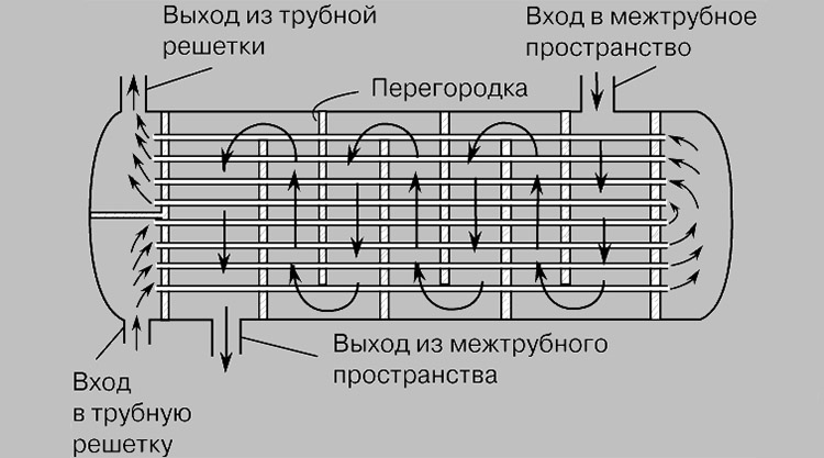
It should be noted that the screw compressor cooling system can also be water. In this case, the radiators 12 and 13 of the compressor are tubular heat exchangers in which the cooling of the working medium (oil, compressed air) is provided by the circulation of water (or other cooling agent) in the annulus of the heat exchanger.
The use of water cooling allows:
- reduce the noise level produced by the compressor during operation;
- refuse to install ventilation ducts to remove hot cooling air from the compressor.
Oil circuit
The oil from the bottom of the oil reservoir 8 returns to the screw block 3 under the action of the pressure maintained inside the reservoir due to the presence of the minimum pressure valve 10.
Depending on the temperature, the oil can move either along the "small" circuit (oil reservoir 8 - thermostat 11 - oil filter 7 - screw block 3), or along the "large" one (oil reservoir 8 - thermostat 11 - oil cooler 12 - oil filter 7 – screw block 3).
The oil temperature is very important for the long term trouble free operation of the compressor.
Too low temperatures can cause condensation from the air even during the compression stage and “emulsify” the oil, which will significantly impair its performance. Too high a temperature significantly reduces the life of the oil and also causes excessive thermal deformation of the compressor rotors, which can lead, in the worst case, even to seizing the compressor.
As you can see, there is nothing complicated in the device of a screw compressor. Modern screw compressors are undeniably reliable and efficient for the production of compressed air in both large industrial plants and small businesses.
That's all.
If you have any questions, you can ask them in the form below. We will respond within 1-2 business days.
Sincerely,
Konstantin Shirokikh & Sergey Borisyuk


History of sky lanterns
Job description: concept, purpose, structure, procedure for compiling and formalizing Purpose and content of job descriptions for managers
Interview questions What job are you going to work on?
What to do if the boss criticizes all the time If the boss does nothing
How to understand: will the kitten be fluffy?