Lecture 10
The principle of operation of a screw compressor. Screw compressors, like piston compressors, belong to the class of positive displacement compressors. The increase in gas (steam) pressure in them is achieved by reducing the closed volume formed by the cavity of the screws and the walls of the housing.
Depending on the phase state, the phase ratio and the composition of the working medium, screw compressors are divided into the following types:
1) screw oil-filled compressors (VMK);
2) dry screw compressors (VCS), in which the main parts can be cooled by steam or liquid;
3) wet compression screw compressors operating with the injection of a relatively small amount of liquid into the working cavities, mainly in order to reduce the temperature of the compressed gas.
Currently, screw compressors are mainly used in refrigeration machines. Oil-filled screw compressors have found their predominant application in refrigeration. The oil is injected into the working cavities of the VMK, where it seals the gaps between the working parts of the compressor, removes the heat of gas compression from heated parts, lubricates the compressor and reduces the noise level.
According to the number of main parts (rotors), screw compressors can be single-, double- and multi-rotor. The latter are not widely used. Single-rotor compressors have found some use. The most common are twin-rotor screw compressors. On fig. 10.1 shows a structural diagram of a twin-rotor refrigeration oil-filled compressor.
The compressor consists of a housing 2, having a vertical connector, front cover 1 with a suction chamber and a back cover 3. A master (VSH) 5 and a slave (VM) are placed in the cylindrical bores of the body 4 rotors rotating in support bearings 6. On the middle thickened part of the rotor, the teeth of the VSH and VM screws are cut, which are mutually engaged, like gear wheels. Axial forces acting on the rotors are perceived by thrust bearings 7. Part of the axial force is removed by unloading pistons 8. A spool is placed in the lower part of the body in the area of steam compression (in a cylindrical bore). 9, designed to control the flow of the compressor. The presence of a spool is characteristic feature screw compressors, which allows you to adjust the supply over a wide range.

Rice. 10.1. Twin-rotor refrigeration screw compressor (VMK)
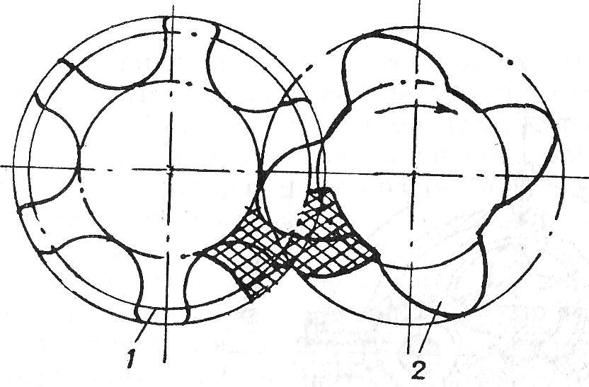
The compressor housing has a suction port and a discharge port located approximately diagonally when viewed from the side of the screw barrels. The screws are helical coarse-module spur gears of constant axial pitch with teeth of a special profile (Fig. 10.2). The teeth of the paired screws during mutual running-in form a theoretically backlash-free connection. In the cavity (depression) between the teeth of the sludge chamber, gas enters through the suction window. The suction window occupies only a part (albeit a large one) of the end area swept by the screw teeth (Fig. 10.3).
Rice. 10.2. Rotor profiles:
1 - slave; 2 - leading
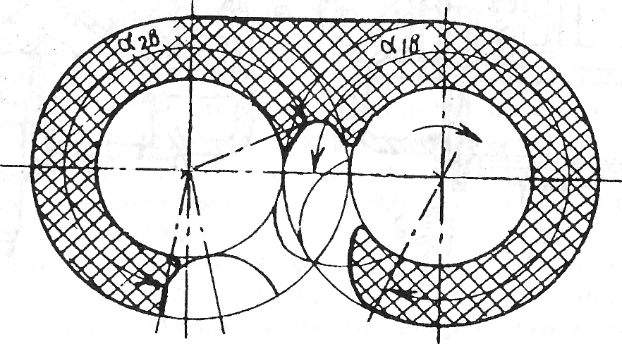
Rice. 10.3. Suction window (shaded)
Screw compressors modern design appeared relatively recently. In 1949, methods for calculating screw compressors and tools for manufacturing screws were created in our country, and in 1952, the first samples of air and gas machines were manufactured that worked with water injection into the working space.
In the late 50s and early 60s of the XX century. oil-injected screw compressors, called oil-filled compressors, appeared. Their designs are somewhat simplified compared to dry compression compressors and machines operating with the injection of a non-lubricating droplet liquid. The connection gears turned out to be redundant, since in the presence of lubrication, mutual contact of the compressor screws is allowed, which ensures their kinematic connection. The seals and bearings have been simplified.
The principle of operation of a twin-rotor screw compressor (both dry and oil-filled) is as follows.
When the next cavities of the VShch and VM screws approach and connect with the suction window, the process of gas suction begins (Fig. 10.4). By this time, only a part of the volume of the cavities was freed from the teeth. As the screws rotate, the volume of cavities released increases, and the suction process continues. After the screw cavities are detached from the suction cavity, the transfer process begins.
Rice. 10.4. Screw compressor operation scheme:
1 - discharge cavity; 2 - conditionally straightened gutter (helical cavity)
one rotor; 3 - tooth of the second rotor, which is included in the cavity of the first rotor;
4 - suction cavity
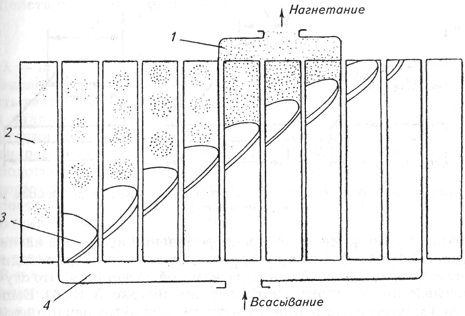
With further rotation, the cavities of the VShch and VM of the screws are gradually filled with the teeth of the paired screw. The volumes of the cavities filled with gas gradually decrease, because after the end of the processes of suction and transfer, the cavities have not yet approached the injection window, located at the opposite end of the screws, and have not connected with it. The gas, moving along the cavities of the screws towards the end face and the injection chamber, is simultaneously compressed and its pressure rises.
The injection window, located mainly at the end and partly on the side of the screws in the compressor housing, has such dimensions that, on the one hand, provide a given internal gas compression pressure in the cavities of the screws, and on the other hand, an acceptable gas flow rate through the injection window. At the moment of connection of the cavities with the injection window, the process of internal compression in the compressor ends and the process of injection (pushing out) of the working substance begins. It should be borne in mind that not a single pair of cavity formed by the VShch and VM screws can be connected simultaneously with the suction and discharge chambers.
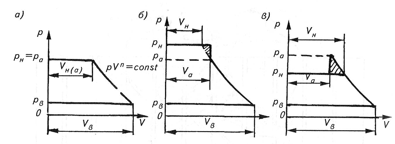
theoretical work cycle. The theoretical cycle of operation of a screw compressor consists of isobaric suction and discharge processes and an isentropic compression process (neglecting heat and mass transfer between the working substance and the external environment). Possible theoretical compressor cycles are shown in fig. 10.5. Unlike a piston compressor, there is no specific, structurally designed dead space in a screw compressor, so the suction process is conventionally depicted in the diagrams starting from the ordinate axis, and the injection process ends on the same axis.
Rice. 10.5. Theoretical screw compressor cycles for various operating modes
Due to the absence of self-acting valves on the discharge, the internal compression pressure r a may not match the pressure r n, which is reflected in the nature of the flow of injection processes (Fig. 10.5, b, c). If r a
then gas compression occurs at the moment of connection of the steam cavity with the injection chamber. This is a case of so-called out-of-geometric contraction (Fig. 10.5, b). If p a > r n, then at the moment of connection of the cavity with the chamber, the gas will expand, and the work expended on its "clamping" turns into heat. This is the most unfavorable mode of operation of the compressor. The shaded sections of the diagrams correspond to energy losses (Fig. 10.5, c).
The most economical is the mode in which the pressure r a= r n, i.e. they match. This mode is called the main one (Fig. 10.5, a).
Parameters of screw compressors. The theoretical volumetric flow of a screw compressor is determined by the design and kinematic parameters of the compressor:
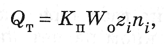
where K p- coefficient of use of the volume of the steam cavity
(K p \u003d W n / W 0); W 0 - the total volume of the steam cavity, determined by the formula
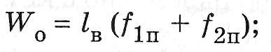
l in - screw length; f 1p, f 2p - the area of the depressions between the teeth in the end cavity, respectively, VShch and VM screws; W p- the volume of the steam cavity at the moment of the beginning of gas compression in it, i.e., at the moment of the beginning of its volume decrease; n i- propeller speed (i = 1,2); z i- the number of teeth of the screw (it is known that z 1 n 1 \u003d z 2 n 2). The formula for Q t can be represented as follows:
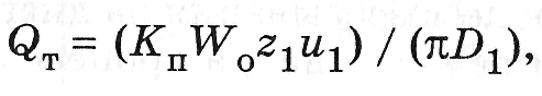
where u 1 - circumferential speed on the outer circumference of the lead screw; D 1 is the diameter of the outer circle of the same screw.
Actual flow of screw compressor
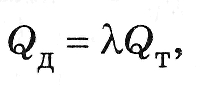
where λ is the feed rate.
The experimentally found value of the feed rate takes into account the influence of various factors on the feed. The main ones are:
leakage of the working substance through the cracks in the suction cavity;
Hydraulic resistance of the suction tract;
· heating of working substance on absorption;
thermodynamic properties of the working substance;
centrifugal forces acting on the working substance.
In a screw compressor, a geometric compression ratio ε g is distinguished, as well as an internal π a and external π n degree of pressure increase.
External pressure ratio in the compressor stage is equal to the pressure ratio in the discharge chamber r n to the pressure in the suction chamber r in, i.e. π n \u003d r n / r in. Under constant external conditions and steady-state operation of the machine, the external degree of pressure increase does not change with a change in the rotational speed of the rotors.
Internal boost rate pressure is equal to the ratio of the pressure in the steam cavity at the moment of its connection with the discharge window to the suction pressure r in, i.e. π a \u003d r a / r in
Assuming the compression process in the first approximation to be polytropic, occurring at a constant amount of working substance, the pressure ratio can be expressed in terms of the ratio of the corresponding volumes:
where W 3- the filled volume of the paired area of the screw teeth from the beginning of their geometric penetration into the cavity to the beginning of the connection of the cavity with the injection window. Volume difference W0 - W3 is the volume of the cavity at the moment of its connection with the injection port.
geometric compression ratio called the volume ratio. This degree is determined by the expression
ε g = W n /(W 0 - W 3).
This ratio is a function of only the geometrical parameters of the screws: the suction and discharge windows, i.e., the values embedded in the design of the compressor.
The compression ratio of domestic VMK lies in the range of 2.6 ... 5.0.
For dry compression screw compressor, indicated capacity
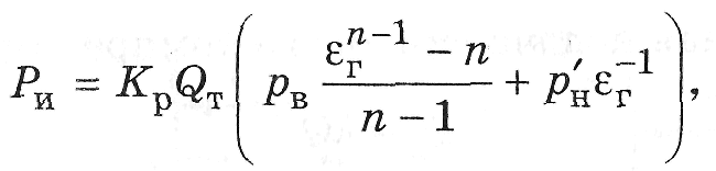
where K r - a coefficient that takes into account the influence of the deviation of the polytropic of the actual compression process from the conditional polytropic, as well as the influence of volumetric losses; r" n- pressure in the steam cavity (p "n \u003d p n + ∆p n), where ∆p n- losses in the discharge path). The effective power supplied to the compressor,
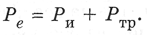
Power R TR depends on mechanical friction and other types of resistance that cause losses. Friction losses are taken into account using mechanical efficiency
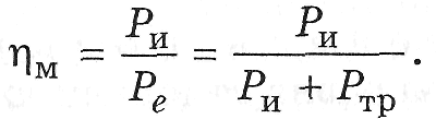
The energy perfection of the compressor is characterized by an effective efficiency equal to the ratio of the adiabatic power R a(taken as "reference") to power R e, connected to the compressor:
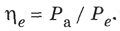
Compressor efficiency indicator
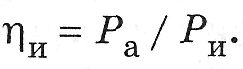
![]()
The nature of the dependence of the mechanical efficiency of screw compressors on the external degree of pressure increase π n is shown in fig. 10.6.
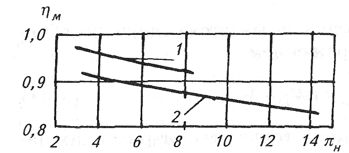
Rice. 10.6. Dependence of mechanical efficiency on external pressure ratio for screw compressors:
1 - dry compressors; 2 - oil-filled
The characteristics of the videoconferencing system are shown in Fig. 10.7.
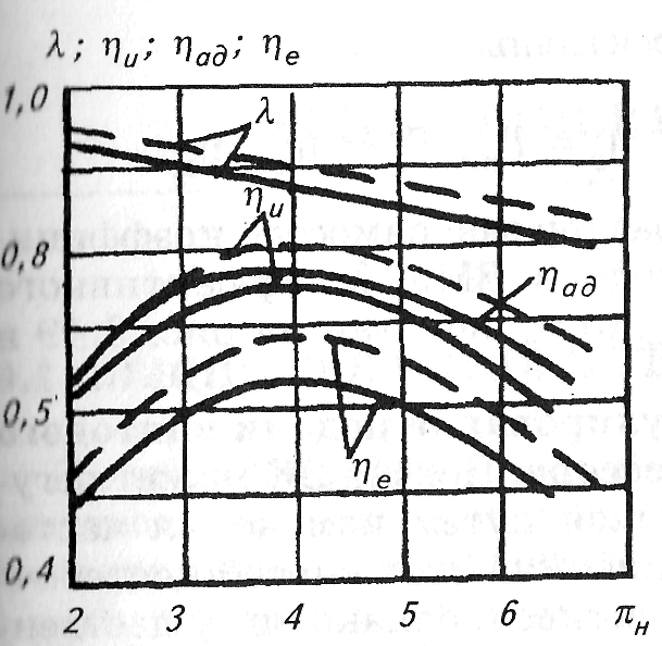
Rice. 10.7. Characteristics of dry screw compressor:
uncooled housing;---------cooled housing
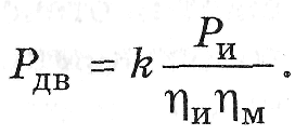
The power of the engine driving the compressor must take into account the losses in the intermediate gear, and also have some margin of 5-10% in addition (K = 1.05-1.10) to compensate for possible deviations of the calculated values from the true ones:
The power of screw oil-filled compressors (VMK) is spent on compressing and moving the working substance R and, to overcome the friction of the rotors on the steam-oil mixture R um, for transporting oil to the discharge side R m, for friction in bearings, mechanical seal, balancing pistons Р tr.
Thus, the equation for determining the effective power of the VMC can be written in the following form:
internal power
Estimated indicated power P and is determined by the equation
where Q m is the flow rate of the oil solution, which occupies part of the volume of the paired cavities on the suction side; p i- the average indicator pressure of the actual IUD, determined by the indicator diagram.
The energy efficiency of the VMC is determined by the following
internal adiabatic

mechanical
efficient
The nature of the dependences of the VMK feed rate λ, effective efficiency λ e from π n is shown in fig. 10.8 and 10.9.
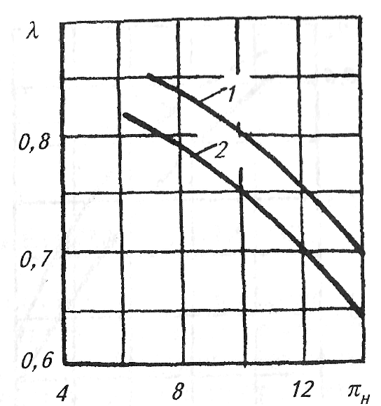
Rice. 10.8. Dependence of λ screw oil-filled compressor on π n
for various oils: 1 - XC-40; 2- XC-50
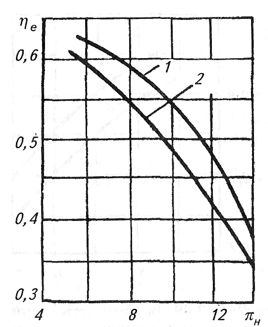
Rice. 10.9. Addiction η e oil-filled compressor
π n for various oils:
1 - XC-40; 2 - XC-50
Regulation of screw compressor supply. The supply of VC can be adjusted by changing the speed. This method is quite effective, but it significantly complicates the drive motor control system.
An important advantage of screw oil-filled compressors is the ability to regulate their flow in a wide range: from full to about fifteen percent due to the presence of a spool 9 (Fig. 10.1). Moving along the axis towards the discharge end, the spool opens up steam from the working cavities to the suction chamber, thereby actually reducing the working length of the screws and, consequently, the compressor supply. When starting the compressor, it is necessary to reduce the power consumed by it to a minimum. For this purpose, the spool is moved to the extreme position, towards the discharge cavity, thereby ensuring the minimum compressor flow and, accordingly, the minimum starting power.
The use of a control spool allows for one of the most cost-effective ways to control flow, resulting in significant energy savings in the long run.
Any type of compressors or compressor devices is used to compress and then supply a pressurized air or gas medium. Screw compressors or, as they are also referred to, screw air compressors, are a subtype of rotary compressor devices. Here, the compression of the medium is realized by the rotation of two rotors. The rotors are interlocked and equipped with helical teeth.
Compressors screw type, as mentioned above, belong to the class of rotary compressor units of volumetric action, the compression of the medium in which occurs with a decrease in the closed volume. The compressed air supplied from the compressor can be used as energy for actuators, for the implementation of various technological processes using compressed air.
Modern industry needs high-quality productive and economical equipment, in particular, compressor units, and this need is constantly growing.
The invention of screw-type compressor devices of various designs was facilitated by such factors as high demand and a variety of operating conditions. Screw compressor devices, like other compressor equipment, are different both in terms of performance and in many other criteria.
How a screw compressor works
Types of screw compressors
Today, many different types of screw compressor devices are manufactured. They should be grouped into two groups:
- with single screw
- with double screw
screw compressor design single screw involves the use of a central rotor, which acts as a screw. On both sides of the rotor there are two or one gear. The central screw causes the rotation of the rotors, which compress the gases or air entering the inlet of the compressor device.
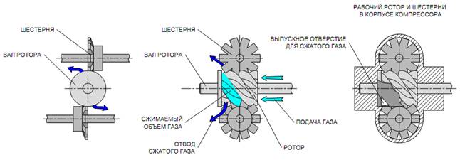
The principle of operation of a single screw compressor
twin screw the compressor is equipped with two rotors: working and driving or main and auxiliary. Screw type compressors do not have valves at the inlet and outlet. A medium, such as a refrigerant, is drawn into the compressor from one side and exited from the other side. Rotating in different directions, the rotor compresses the gaseous refrigerant. The rotation of the working rotors is facilitated by the rotation of the central drive rotor, the design of which is made in the form of a screw. Hence the name: "screw" compressors.
The refrigerant vapors, entering the inlet of the screw-type compressor device, cool the drive motor, then pass through special channels into the cavity of the outer zone. Here are the rotor gears that compress these channels. An outlet equipped with a valve releases the refrigerant from the compressor unit.
The compression of the medium, air, other gases or refrigerant occurs in compressors of this type according to the same principle as in the first case.
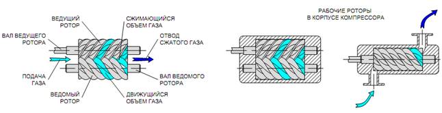
The principle of operation of a twin screw compressor
Differences of screw compressors by drive type
The design of screw compressors provides for the use of 4 types of drives: belt drive type, gear drive type, direct and direct type with frequency regulation.
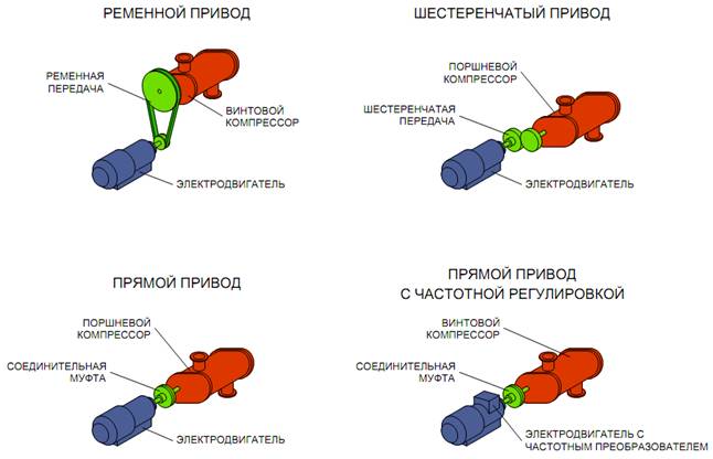
- Screw compressor equipped with belt drive, quite easy to operate. This is a great advantage, as there is no need to attract highly qualified personnel for its technical inspection. This type of compressor is serviced, as a rule, by the forces of the enterprise. Another plus of this category of compressors is the possibility of its adjustment. The number of revolutions of the screw of the compressor device is in no way related to the number of revolutions of the engine, there are variations in the gear ratio. The disadvantages inherent in this type of compressors should also be noted:
- rather low efficiency, which directly depends on the wear of the belt;
- strong noise in comparison with other types of screw compressor devices;
- rapid wear of the belts due to the presence of dust in the air.
- For screw compressor units with gear drive type is characterized by low noise level and smooth running of the drive. They have a very high efficiency (98% and above). High performance indicators contribute to the use of this type of compressor equipment in difficult conditions, for example, in industries where high level dust generation, such as the cement packaging department or the flour milling department. The disadvantages of this type of equipment include such moments as impossible adjustment, expensive repair work because knowledgeable specialists are required to perform these works. They are not always available at the enterprise, and the involvement of third-party organizations is worth the additional cost.
Screw compressor with gear drive type is suitable for enterprises with severe operating conditions. They can be installed both in small workshops and in large enterprises using compressed air. - Screw compressor equipment with direct drive have an extremely high efficiency (99.9%). It does not react to the ingress of dust particles or other impurities into the mechanisms, is not susceptible to aggravated operating conditions. The smooth running of the screw compressor drive is a consequence of the long service life of the motor. The service life of the compressor device itself can be tens of years without overhauls. Like any type of compressor, the direct drive screw compressor has both negative points as an impossible adjustment (because the RPM of the motor is the same as the RPM of the compressor head). The maximum operating pressure of the compressor cannot be changed.
The screw compressor with direct drive is suitable for enterprises with severe operating conditions. It can be installed both in small workshops and in large enterprises where compressed air is used, but not in enterprises where it is necessary to change the maximum working pressure of compressor equipment. - Screw compressor devices with direct drive with frequency control are today one of the most advanced types of compressors. This fact is recognized by both compressor manufacturers and consumers. They are characterized by extremely high efficiency (99.9%), they are adjustable in capacity and pressure, they are suitable for any application, they have a smooth drive. It can rightly be stated that a screw compressor of this type is practically devoid of shortcomings, perhaps only a high price of equipment can be attributed to a small number of them, which is not an obstacle to the growing demand from consumers. Screw compressor devices with direct drive with frequency regulation can be applied in any enterprise using compressed air.
Among other types of screw compressor equipment, there are diesel And rotary screw compressors.
Diesel screw compressors are used mainly when performing work in open areas without access to electricity. These compressors are powered by diesel fuel. Their design is very compact, they are maneuverable, they are easy to transport, they can operate in extreme weather conditions, at elevated temperatures, humidity, dust, their reliability and high quality indicators captivate. These advantages have contributed to the fact that diesel screw compressors have gained such popularity among users.
Rotary screw compressors were mastered in the 30s of the 20th century and have long been used in various fields industry. They are also very popular among users due to many positive factors. This type of compressor has its own characteristics:
- they are equipped with worm rotors, which stabilize the operation of the compressor and ensure its endurance;
- this type is designed without valves, which reduces the load on the compressor itself;
- with an increase in the speed of rotation, the productivity of the compressor increases;
- rotary screw compressors have a screw section of various shapes;
- rotary screw compressors are distinguished by their small form.
Screw compressors are also distinguished by the location of the cylinders: vertical and angular.
According to the type of refrigerant used by the compressor, they are divided into: freon, ammonia, chloromethyl and sulfur dioxide. Freon compressors (small) are the most widely used today.
According to the conditions of use, compressors are distinguished as conventional, operated under normal conditions, and special, which are made in a tropical version.
The boiling point of the refrigerant defines compressors as low, medium and high temperature.
According to the type of cooling, water-cooled compressors and air-cooled compressors are distinguished.
Compressor equipment is known for the variety of its design, different in design, performance, principle of operation, etc. Hence the division into the following types according to signs:
- stationary and mobile;
- horizontal, vertical and inclined cylinders;
- single-stage and multi-stage;
- single-cylinder and multi-cylinder.
According to the medium used for compression, compressors are divided into the following types:
- gas, intended for gas or a mixture of several gases;
- air, designed for compression air environment;
- special compressors or multipurpose compressors used to compress a variety of gases alternately;
- multi-service compressors, these are also special compressor devices designed to simultaneously create an excess pressure of various gases;
- circulation compressors designed to provide continuous circulation in a closed circuit.
- Oil-flooded compressors: for such types of compressor equipment, one rotor is the leading one, and the other acts as a driven rotor. Such types are installed in working production shops.
- Oil-free compressors used in industries such as food, pharmaceutical and chemical industries. They are divided into two subspecies:
- Screw compressor devices for dry compression. They are equipped with synchronous motors. These engines are driven by both propellers. Their performance is lower than that of oil-filled compressors. They do not have oil, which means they do not have heat dissipation.
- Water-filled compressors, which are rightfully considered the most technologically advanced model. They combine all the positive aspects of oil-free and oil-filled types of compressor equipment. Water-filled compressors have optimum performance. This model is considered clean in terms of environmental damage. Instead of oil, she uses ordinary water, which is not an expensive product. Internal cooling also works, making the thermal load on the compressor components minimal. From here, the service life of the compressor device increases, its reliability and safety as a whole, the reduction in energy costs by almost 20%, therefore, the device is cheaper, because it does not have oil filters, containers for used oil liquid.
Design and principle of operation of a standard screw compressor.
With the simplest and most common arrangement, air passes through the suction valve and air filter (1) with pollution sensors, entering the screw pair (2). Screw pair (2), in which air is mixed with pre-cleaned oil, is the "heart" of the compressor. The air-oil mixture formed as a result is sent by means of a screw block to the pneumatic system. The compressor is equipped with a separator in which oil and air are separated. The air separated from the oil enters the outlet part of the compressor, after passing through the cooling radiator device (9). The oil flows back into the screw pair. The temperature determines the further course of the oil: it moves either in a small circle, and if it needs to cool, then it goes through the radiator in a large circle. The temperature is controlled by a thermostat (7) which controls the oil as it flows through the radiator (8). The oil remaining in the separator is transferred through the branch pipe (10) to the screw mechanism. An electric motor drives a screw pair. The compressor is turned on and off automatically by a controller or pressure switch. In the diagram below, you can clearly see the layout of a standard screw compressor described above.
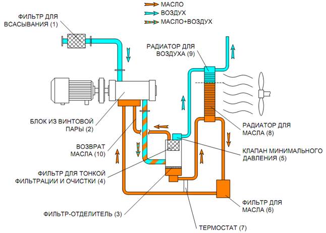
1. Suction filter; 2. a block of a screw pair; 3. Filter separator; 4. Filter for fine filtration and purification;
5. Valve min. pressure; 6. Oil filter; 7. Thermostat; 8. Oil cooler; 9. Radiator for air.
All kinds, types and models of screw compressors in their various designs have many advantages in comparison with other types of compressor equipment. And it is precisely because of their advantages that screw compressors are most widely used today in various fields of production. The use of a screw compressor in production areas significantly reduces the cost of producing compressed air and thereby increases the profitability of the entire production as a whole.
So speaking of positive aspects screw compressors, it should be mentioned, first of all, their following advantages:
- they are reliable;
- able to work for a long time without recharging (around the clock);
- easy to install and connect;
- low operating costs of a screw compressor;
- low noise level;
- equipment automatic system management;
- high purity of the resulting compressed air;
- low energy consumption for cubic meter produced air;
- quite high performance and
- high rate of energy savings.
A significant advantage of the above advantages of screw compressors is the fact that these devices are quite small in size. Screw compressors are used in conditions small industries where there is little compressed air consumption. This type of small-capacity screw compressor units is very economical, with good reliability in use and is quite easy to maintain.
The modern market for compressor products today offers variants of screw compressors, which, in terms of performance and power, correspond to centrifugal or reciprocating machines of the same purpose.
The disadvantages of screw compressor equipment include the following negative points:
- the constructive complexity of the mechanisms for regulating the degree of compression of the air obtained at the outlet;
- the need to equip an effective oil separator and oil cooler;
- underestimated performance (up to 20% of the maximum value) entails a decrease in the efficiency of the intermediate suction device.
Screw compressors are widely used today in the chemical and petrochemical fields, in the field of gas processing, in the oil field. A typical application criterion is the cooling of hydrocarbons, fluorocarbons, ammonia refrigerant. The second criterion for the use of these compressors is the capture of vapors and gases, in the process of compressing fuel gases, natural gas, as well as gases from organic waste, tail gases, helium and CO2.
Over the last twenty years screw devices began to be widely used in the gas industry when using them as booster equipment, for collecting gases, in the field of gases dissolved in oil.
Screw compressor devices are used, as a rule, for a large amount of process gases, they are used for cooling during technological processes. In the gas industry, screw compressors are used as stand-alone well boosters, low-stage boosters for reciprocating compressor machines, to collect gases with low pressure. They are used in the compression of flue gases, associated petroleum gas. In industries dealing with purified and raw gases as well as sour gas (with H2S and/or CO2 concentration > 80%), for volatile gases (hydrogen) and for gases with high molecular weight and specific viscosity up to 2.0, they can also be apply.
Oil-free screw compressors have been used for process gases since the 1970s. Oil-flooded screw compressors are used in many applications. production processes since the 1980s
The staff of Intech GmbH (Intech GmbH) is always ready to provide additional technical information on the proposed compressors of various types and types.
Vacuum compressor systems, vacuum compressors
Fans. Turbo fans. Calculation and selection of fans
Screw compressors
Booster compressor station
Compressor units for acid gas, hydrogen, corrosive gases, coke oven gas, oxygen
Diaphragm compressors
The main characteristics of the compressor. Compressor performance. Compressor capacity Application of reciprocating compressors Central site and supplied equipment
Lecture 5
Topic– «Screw compressors»
Target: Study of the device and principle of operation of screw compressors for traction rolling stock.
Plan:
Screw type compressors.
The principle of operation of screw compressors.
5.3. Locomotive screw compressor units of OAO Transpnevmatika.
5.4. The principle of operation of the pneumatic source system of the electric locomotive KZ4A.
1. Kurilkin D.N., Panchenko M.N., Bazilevsky F.Yu., Grachev V.V., Grishchenko A.V. Automatic rolling stock brakes. Electronic textbook. // St. Petersburg, FGOU VPO PGUPS, 2010.
2. V. I. Krylov, V. V. Krylov "Automatic brakes of rolling stock". Moscow, Transport, 1983.
For today air compressors represent a wide range of installations that differ from each other in the principle of operation, equipment and device, operating and other characteristics. Each type of equipment has its own advantages and features that make the choice of a particular installation the most optimal. However, the most popular are screw compressors, the design of which ensures high efficiency and reliability of the equipment.
Screw type compressor device
The units included in the group of screw compressors may be different, but at the same time they have equipment common to all types of equipment of this type. The devices included in the screw compressors perform certain functions, while ensuring the efficient and uninterrupted operation of the installations.
So, the composition of screw compressors includes the following components:
Suction air filter - performs the function of cleaning the air that enters the compressor unit. It often consists of two elements - a pre-filter located in the place where the air is taken in, as well as a filter located in front of the inlet valve.
Inlet valve - provides regulation of the performance of the entire compressor and is equipped with pneumatic control. The regulation of the operation of the installation is ensured by the transition of the valve to idle.
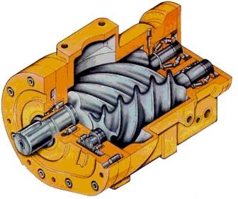
Screw block - is one of the main working elements of the screw type installation. The screw block consists of two rotors located parallel to each other, one of which has a concave screw profile, and the other has a convex one. It is the presence of rotors that distinguishes the device of screw compressors and the principle of their operation from other types of installations.
Belt drive - consists of two pulleys that set the required speed of rotation of the rotors. One of the pulleys is located on the screw pair, and the other is on the engine.
Electric motor - provides rotation of the screw pair by means of a clutch, gearbox or belt drive.
Oil filter - cleans the oil before it returns to the screw block.
Oil separator - a tank made of metal, in the middle of which there is a partition with holes. The force of inertia that occurs when the flow swirls leads to air purification from oil by a special filter.
Thermostat - provides the most optimal temperature regime. At low oil temperatures, the thermostat allows oil to pass without affecting the cooling radiator, which allows you to quickly obtain the most optimal temperature in the installation.
Oil cooler - performs the functions of cooling the oil after it has separated from the compressed air.
Aftercooler - cools the compressed air to the required level before it is supplied to the consumer.
Safety valve– provides safe work device and prevent damage. This valve is activated by a significant increase in the pressure level in the oil separator tank, which can damage all equipment.
Piping system - has different piping for air-oil mixture, air and oil.
Pressure switch - sets the parameters and mode of operation of the installation, depending on the indicators of the pressure level. So, when the maximum pressure value is reached, the operation of screw compressors switches to idling. When the pressure drops, the unit starts working again.
Control unit - required for electronic control and control over the operation of the equipment, and also allows you to transfer to the display all the necessary operating parameters and characteristics of the compressor.
Fan - designed to take air into the compressor with simultaneous cooling of working parts and equipment.
Screw compressors are a type of positive displacement compressors. Despite the fact that many screw compressors may have various design differences, the principle of operation of most of them is the same. Consider, as an example, the device and principle of operation of the AIRBLOK BD series compressor.
AIRBLOK BD screw compressor sucks atmospheric air through the air filter 1 with replaceable filter element. The purified air then passes through the multifunctional suction regulator. 2 and enters the screw block 3 . Here, the air is compressed and mixed with oil injected into the block in exactly the right amount. The resulting air-oil mixture is forced into the separator 4 where the separation of oil and air takes place.
Purified air passes through the air section of the combined air-oil cooler 5
and enters the compressor outlet.
The oil separated in the separator is returned back to the screw block. Depending on the temperature, it passes either in a small circle or in a large circle through the oil section of the radiator. The thermostat valve controls the flow of oil. Before injection into the screw block, the oil first enters the oil filter 6 where it is cleaned from solid particles.
The drive of the screw pair is carried out from the electric motor 7 through a belt drive 8 .
The automatic mode of operation of the AIRBLOK BD compressor is provided by the microprocessor control panel.
There are six main operating modes of the screw compressor.
· Start mode. This mode is necessary to minimize the load on the electrical network at the time of starting the compressor. At the moment of start-up, the electric motor is switched on according to the "star" scheme, which ensures the minimum load on the network. After 2 seconds, at the command of the timer, the electric motor switches to the “delta” circuit and the compressor goes into operating mode.
· Operating mode (pressure mode). In this mode, the compressor produces compressed air and the pressure in the system begins to rise. When the maximum pressure is reached, the pressure sensor (or pressure switch) is activated and the compressor switches from operating mode to idle mode.
· idle mode. The idle mode is transitional and serves to transfer the compressor from operating mode to standby mode or completely off. In idle mode, the compressor motor and screw group continue to operate, but without the production of compressed air. At the same time, the internal circuit of the compressor is unloaded - the zone between the suction valve and the minimum pressure valve. Thanks to the idling mode, the compressor is switched off without oil ejection through the suction valve into the air filter area.
After the idle time has elapsed, the motor is switched off and the compressor goes into standby mode (or shuts down).
If, during the operation of the compressor in idling mode, the pressure in the working pneumatic line drops to the minimum operating pressure (compressor cut-in pressure), then the remainder of the idling time is reset to zero, and the compressor switches back to operating mode.
· Standby mode. The standby mode continues until the pressure in the working pneumatic line drops to the minimum working pressure. The compressor can be in this mode for an arbitrary time, which depends on the air flow in the pneumatic line.
· Shutdown mode. The compressor switches to this mode, which is used for normal shutdown, when the button is pressed. STOP. If at the time of pressing the button STOP If the compressor was in operating mode, it first goes into idle mode, after which it turns off.
· Emergency shutdown mode. The compressor enters this mode when the emergency stop button is pressed. ALARM- STOP. This mode is used only in emergency cases to immediately turn off the compressor. When you press a button ALARM- STOP the compressor is switched off without switching to idle mode (respectively, without unloading the internal circuit). Therefore, as a result of an emergency stop, oil may be ejected through the suction valve into the area of the air filter.
Preparing the compressor for operation and putting it into operation
The procedure for preparing a screw compressor for operation is as follows. Let's analyze it using the example of NEW SILVER and MICHELIN compressors.
1. Open the package, check the completeness, make sure there are no mechanical damages. IMPORTANT! The operation of a compressor with mechanical damage is strictly prohibited!
2. Carefully read the instruction manual for the compressor. It is better if a specially appointed person (who has electrical engineering training and skills in working with hardware) takes care of this, who will continue to operate the equipment.
3. In accordance with the recommendations set out in the operation manual, select and equip a place where the compressor will be installed in the future. For normal operation of the compressor, the temperature environment indoors should be between +5°C and +40°C. The installation site of the screw compressor must be protected from moisture (precipitation), spacious and equipped with good natural ventilation. Compressor sucks a large number of air, which goes, among other things, to its own cooling. The compressor room must be free from dust, as dust trapped inside the compressor will clog the air filter and will also prevent heat from being removed from the cooling radiator.
For ease of maintenance, the compressor is installed at a distance of at least 1 m from the walls. Free space around the compressor is also necessary for the normal circulation of cooling air around it.
IMPORTANT! If the compressor room is small (the distance from the compressor to the walls is less than 1 m, and the ceiling height is less than 2.5 m), then you should contact a specialized organization that will prepare a project to provide the room with compressor forced ventilation.
4. Once you have chosen a place to install the compressor, lift it with a hoist (at least 900 mm long) and place it on four anti-vibration mounts.
IMPORTANT! Do not anchor the compressor rigidly to the floor.
5. Connect the compressor to the mains. The connection must be carried out by a suitably qualified person. The socket and circuit breaker must be installed no more than 3 m away from the compressor.
6. Check the voltage in the mains. It must correspond to the voltage indicated on the rating plate (tolerance +/- 6% possible). For example, if the label indicates a supply voltage of 400 V, then the minimum value of the mains voltage should be 376 V, and the maximum voltage should not exceed 424 V.
When starting the compressor for the first time, it is necessary to check the direction of rotation of the screw block. The correct direction of rotation must be indicated (in this case, it is indicated on the compressor housing panel and on the screw block housing). The phase sequence is very important. Even a small amount of reverse rotation of the motor and screw assembly can lead to compressor failure!
IMPORTANT! After purchasing the compressor, be sure to clarify whether a phase control relay is installed on it! This can be obtained from the Equipment Supplier, or checked by wiring diagram, which is necessarily presented in the compressor operating manual.
If the phase control relay is not included in the compressor design, then it must be installed additionally! This will avoid failure of the elements of the electrical part of the compressor and the screw block.
7. Connect the compressor to the pneumatic line. The connection of the compressor to the line must be made through a flexible hose. It is forbidden to connect the compressor directly to a rigid (stationary) pipeline!
Connection is made either through a valve installed on the receiver, or through the outlet on the dryer (on compressors with a built-in refrigeration dryer).
IMPORTANT! The flexible hose must have a larger diameter or the same diameter as the outlet fitting (outlet cock) of the compressor.
Do not install a non-return valve between the compressor and the pneumatic line. It is already installed inside the compressor.
8. Check the oil level. It should be in the middle line of the viewing window. If necessary, add oil to the required level, without allowing it to leak and get on the outer surfaces of the compressor.
9. Check the tension of the drive belts. Recommendations on the allowable tension of the drive belts and the rule for their control are given in the compressor operation manual.
10. Check if the compressor emergency stop button is blocked ( EMERGENCY- STOP or ALARM- STOP)? In case of blocking, unlock it (with a slight twist).
After turning on the screw compressor, check its performance. The method of experimental determination of compressor performance is discussed in detail in the previous issue of our journal (see "KiP", June 2014). The only caveat is that in technical specifications screw compressor, its volumetric productivity is indicated, equal to the volume of air produced per unit of time. Volumetric productivity is expressed in normal cubic liters(or meters) per unit of time, indicating the suction conditions. Therefore, if the compressor capacity is 1000 Nl/min at an ambient temperature of 0°C and a pressure of 1.013 bar, this means that the compressor produces an amount of air that, under the indicated suction conditions, occupies a volume of 1000 liters.
This is the fundamental difference between the performance of a screw compressor and the performance reciprocating compressor, for which the theoretical performance (suction capacity) is indicated in the technical data.
In the next issue of the journal, we will consider the features of the Maintenance screw compressor.


Living and dead water: myth or reality, what is the power of living and dead water?
Craniosynostosis, or premature fusion of the bones of the skull Frontal crest in a child
Beautiful hair How to achieve hair density at home: useful tips
Why mosquitoes bite some people, but not others
How to achieve beautiful hair