The use of screw compressors in refrigeration is due to the need for large values required cooling capacity. Screw are successfully used as part of medium, high and low temperature. They are popular with due to their reliability and high efficiency. The principle of operation of a screw refrigeration compressor is based on the continuous movement and compression of refrigerant vapors, thanks to the work of a screw pair.
The basic geometry of a screw compressor. The working cycle has three different phases: ¾ suction. Intake All screw compressors used in refrigeration use oil injection into the compression chamber for lubrication, sealing and cooling. The seal between different pressure levels contains a narrow strip between the rotor gear and its periphery in the compression chamber. Oil is injected directly into the compression chamber in sufficient quantity to minimize leakage and cool the gas. This oil is subsequently separated from the gas in an oil separator.
The working parts of a screw refrigeration compressor are screws, the so-called rotors. Compressors with two rotors in design are mostly common. One of them is the leader, the second is the slave. They rotate relative to each other in a closed housing and "engage" with each other with teeth made in the form of spirals. Torque is transmitted to the main rotor by an electric motor, which can be located in one compressor housing, or connected to it through a clutch or other gear.
Using the proper amount of oil allows it to absorb most of the heat from compression, resulting in a low outlet temperature even if the compression ratio is high. Currently, objects with a two-stage system are quite common. Work principles Screw compressor can be described as a positive displacement machine with a volume reduction device. This action is similar to that of the alternative compressor. It is helpful to refer to the equivalent process performed by an alternative compressor to better understand how compression works in a screw compressor.
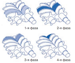
The compression process takes place in the space between the teeth of the screws. With mutual rotation in different directions, the tooth of one rotor enters the cavity of the other, thus reducing the volume of the working area. As the gas moves from the suction cavity to the discharge cavity, the volume decreases and the pressure increases. At the end point, the volume of the working area is reduced to zero, which indicates the minimum dead (harmful) space and the efficiency of the compressor. In screw compressors, the process of suction, compression and discharge takes place continuously.
The gas is simply compressed by the rotation of the associated rotors. This gas flows through the space between the petals as it is transferred in the axial direction from suction to discharge. Suction As the rotors rotate, the gaps between the petals open up and increase in volume. The gas is then sucked in through the inlet and fills the space between the petals as shown in the figure. When the gaps between beats reach their maximum volume, the entrance closes.
The principle of suction in a screw compressor. This process is similar to running a piston in an alternative compressor. The suction-approved refrigerant is stored in two helical cavities formed by the vanes and a chamber where the rotors rotate. The volume stored on both sides and along the entire length of the rotors is defined as the suction volume. This can be seen in the figure. Comparison of suction processes.
Screw refrigeration compressor.
Consider the device of a screw refrigeration compressor using the example of a semi-hermetic compressor from the company. The main elements of the screw compressor are shown in the figure.
The shapes of the profiles of the teeth of the rotors are adjusted so that during the compression process, constant contact is maintained between the screws to prevent gas leakage from the high pressure area to the low pressure area.
Volume displacement reciprocating compressor is determined by the volume of suction, multiplying the area of the cavity by the stroke of the cylinder and by the number of them. In the case of a screw compressor, this displacement is given by the suction volume per wire multiplied by the number of drive motor vanes.
Compression. The spade rotor blades will begin to insert into the grooves of the female rotor at the suction end located at the rear of the compressor. The point of intersection between the male rotor blade and the inner rotor groove is similar to the compression of gas by a piston in an alternative compressor. Unloading In the alternative compressor, this process starts after the opening of the first outlet valve. As the pressure in the cylinder exceeds the pressure above the valve, it opens, allowing compressed gas to be burned for unloading.
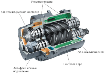
screw refrigeration compressors work with a lot of oil. Its use is necessary to lubricate the screw pair, reduce wear of working elements, seal the gaps between the screws, and also to remove the heat generated during the compression of the refrigerant. This condition requires the installation of oil separators and oil coolers as part of a refrigeration machine based on screw compressors. As a result of oil injection into the gas compression zone, friction in the screw compressor is minimized, and there is no mechanical contact between the rotors.
The screw compressor does not have valves to determine when compression is complete: the location of the discharge chamber is determined by what determines when this occurs, as shown in the figure. The volume of gas in the spaces between the vanes at the outlet is defined as the discharge volume.
Two holes are used: one for radial discharge at the end outlet of the spool valve and one for axial discharge at the outlet end wall. These two entail releasing compressed gas internally, allowing it to be ejected into the compressor unloading area. The positioning of the discharge is very important as it controls the compression as it determines the relationship between the internal volumes. To achieve the highest possible efficiency, the ratio between volumes must be related to the ratio between pressures.
To increase the cooling capacity of screw compressors, especially when used for low temperature purposes, manufacturers have made it possible to use a subcooler (economizer). The use of an economizer (refrigerant subcooler) allows one and the same compressor to obtain significantly greater performance characteristics.
In an alternative compressor, the unloading process ends when the piston reaches the top of the compression chamber and the exhaust valve closes. In a screw compressor, this happens when the space previously occupied by the gas is taken up by the male rotor vane.
Reciprocating compressors always have a small amount of gas that remains at the top of the compression cylinder and expands in the next cycle, thus taking up space that can be used to increase the mass of refrigerant sucked in. At the end of the discharge of the screw compressor, no “harmful” volume remains in the compression chamber, that is, all the gas is thrown out. This is one of the reasons why compressors.
Screw refrigeration compressors are widely used and the ability to control performance without the use of frequency inverters. Multi-stage regulation of cooling capacity is provided by changing the volume of suction gas.
To date, on Russian market, including in Chelyabinsk such manufacturers of screw compressors as Bitzer, Refcomp, .
Compressor screw compressors are capable of operating at higher compression ratios than alternative compressors. Volume ratio In an alternative compressor, the unloader valves open when the cylinder pressure exceeds the outlet pressure. Because the screw compressor has no valves, the location of the discharge chamber determines the maximum pressure that will be reached in fractions before the gas is forced out. Volume ratio is key design feature all screw compressors.
The compressor itself is a volume reduction device. The comparison between the volume of suction gas and the volume of gas in the compression chamber at the opening of the discharge determines the reduction rate of the compressor volumes, which determines the ratio of the compressor pressure to the ratios below.
Screw compressors are class of rotary equipment. The principle of operation of such devices is based on rotation of two rotors, which are called screws. The first sample was released back in 1934 by the Swede Eliot Lisholn. Since then, the invention has undergone many changes, but the principle of operation has remained the same.
Only the suction pressure and volume ratio determine the gas pressure level before opening the discharge chamber. However, in all refrigeration systems, the outlet pressure of the system is determined by the condensing temperature, and the evaporating temperature determines the suction pressure.
The amount of space between the petals. If the ratio between the compressor volumes is too high for a given operating mode, the gas discharge will become too long and the pressure will be higher than the discharge pressure. This phenomenon is called overcompression and is represented by a volumetric pressure diagram as shown in the figure. In this case, the gas is compressed above the discharge pressure, and when the discharge opens, the high pressure of the gas causes it to expand the refrigerant into the outlet pipe, from the compressor. This results in more work than if the pressing was interrupted when the internal pressure was equal to the pressure in the discharge chamber.
To date, screw units almost completely replaced other types of compressors from mobile stations, ship refrigerators, from food, glass, chemical production, and other industries.
We offer you to watch a video about the device and the principle of operation of screw compressors
When the ratio between the volumes is too low for the operating conditions of the system, this is called compression and is shown in the figure. In this case, the opening of the outlet occurs before the gas pressure reaches the outlet pressure. This causes the gas outside the compressor to invade the compression chamber, immediately raising the pressure to the discharge pressure. The compressor must run for more than high level pressure, instead of working with a gradual increase in pressure.
Understanding the basic principles of your work will help you correct use, preventing problems and achieving better overall plant performance. Construction A typical oil sealed screw compressor is a positive displacement machine that has two coupled rotors mounted in bearings to lock their positions in a working chamber with a narrow tolerance to a cylindrical cavity. The drive device is usually connected to the male rotor and this drives the female rotor with an oil film.
Advantages
Screw compressors are designed to increase the performance and life of small motors while cutting energy consumption in half. The advantages of this type of equipment are compact dimensions, not too burdensome weight, reliability, durability.
Using the right amount of oil allows it to absorb most of the heat from compression, resulting in a low outlet temperature even when the compression ratio is high. Unloading In an alternative compressor, this process begins with the opening of the first outlet valve.
Volume ratio In an alternative compressor, the unloading valves open when the cylinder pressure exceeds the discharge pressure. The compressor itself is a volume reduction device. The comparison between the volume of gas in the suction and the volume of gas in the compression chamber at the opening of the discharge determines the reduction rate of the compressor volumes, which determines the compressor pressure ratio through the ratios below. Only the suction pressure and volumetric ratio determine the level of gas pressure before opening the discharge chamber.
Screw units do not require continuous maintenance, as they are able to work offline for a long time. They are quickly mounted in their own frames without a specially equipped foundation, they vibrate minimally during operation.
Screw types are equipped with noise-isolating casings, they work quieter than others. In workshops with them, they are stored as much as possible comfortable conditions for people.
If the ratio between the compressor volumes is too high for a given operating mode, the gas discharge will become too long and the pressure will be higher than the discharge pressure. This causes the gas outside the compressor to invade the compression chamber, immediately raising the pressure to the discharge pressure. In both cases the compressor will still be running and the same volume of gas will be displaced but with more power required than will be used if the discharge ports are positioned correctly to match the volume ratio with the system demand.
Most representatives of the described class are equipped with a digital control board. Due to this, it is easy to change pressure, program process cycles on a timer, and regulate energy consumption. Actions can be performed remotely.
Among the main advantages is the low oil consumption. It takes about 2-3 mg per 1 m3 lubricant, which is several times less than that of modifications. This indicator is important for the quality of the outgoing air. The screw design works cleaner than others, which means it does not need additional filters, it can even be used for pneumatic machines.
This results in a higher energy cost. Variable volume designs are used to optimize the location of the discharge chamber and minimize the power required. Power control Power control in a screw compressor is used to change the amount of gas entering the chamber. This is necessary to ensure accurate control of the suction temperature as the heat load changes. Some common bandwidth control methods.
¾ Sliding valve controlling the unloading chamber; ¾ Rotary valve that controls the discharge chamber and the ratio between the volumes. ¾ The sliding valve does not control the discharge chamber. This type of valve operates through a recirculation duct opening in a high pressure area, which allows some of the gas located between the petals to return back to the suction cavity before compression begins. This method provides good efficiency at partial loads for two reasons. First, the recirculated gas only has to overcome a slight pressure drop before being sucked back until the recirculation chamber opens before compression begins, preventing loss of precompression.
The air cooling principle eliminates the need to build in a circulating water supply system and allows the compressor heat to be reused (for example, for heating workshops).
A story about compressors of one of the manufacturers from a specialist
Second, since the spool valve is movable, the radial discharge can also move. As the suction volume decreases, the opening of the discharge chamber is also delayed while maintaining a roughly equal ratio between partial load volumes and total load volumes for optimal partial load efficiency. A compressor designed to adjust power and change the volume ratio is shown in the figure. In this design, the movable slider is adjusted in the same way as a spool valve.
Device and principle of operation
Compressed air and gas make complex execution systems of pneumatic cylinders, valves and other mechanisms function. The screw compressor is engaged in the conversion of electrical energy into an air-gas push.
Components
Any screw compressor model includes fundamental details:
- Air filter - sucks air into the device, cleans it. Located at the inlet valve.
- Inlet valve - regulates the operation of the unit by switching to idling.
- The main screw block - consists of two rotors of concave and convex shape, located parallel to each other.
- Electric motor - starts and maintains the movement of the screw pair.
- Belt drive - engages the rotors with the engine, provides rotation, maintains speed.
- Oil separator - a tank with a baffle in which air is separated from the oil.
- Oil filter and cooler - cleans, cools the oil lubricant before it enters the rotor compartment.
- Thermostat - monitors the optimum temperature of the engine. At low heating, the oil passes it outside the cooling, speeding up the process.
- Pipelines - a system for passing and connecting departments of air, oil, and their mixtures.
- Safety valve and pressure switch - protect the motor from damage. They work with a significant overpressure in the separator, preventing the failure of the unit.
- The control unit is a system of displays and boards that provides electronic configuration, tracking equipment parameters.
- Fan - helps the air intake inside, at the same time cools the motor elements.
- Aftercooler - brings the compressed air to the optimum temperature before being discharged from the compressor.
 The rotors rotate towards each other, observing the principle of the sheet. The movement of the screws draws air through the inlet filter. The flow passes through purification, mixing with oil, cooling. The resulting mixture enters the system under a continuing screw thrust. Further, the separator separates the oil from the air, the latter exits the compressor into the consuming equipment.
Thus, the work of the screws does all the necessary process with air without outside interference.
Screw compressors have several possible operating modes with specific functions:
- Starting or Start - starts the engine of the device, optimizes the load from the mains. It is activated by pressing a special button, after a few minutes it goes into operating mode. It may be absent if the compressor capacity is minimal and direct start is provided.
- Working - increases pressure to the maximum allowable, then the idle switch relay is activated.
- Idling - characterized by the rotation of the rotors, the continuous operation of the engine. At this time, the gas is pushed through the entire device, the air masses are cooled. It serves to prevent breakdowns, wait for optimal performance, prepare the compressor for shutdown.
- Waiting - comes after idling, until the pressure mark drops to the minimum. The duration depends on the speed of the air outlet. This may be followed by the continuation of work to turn on the relay.
- Stop - regular shutdown of the device.
- Emergency shutdown (Alarm stop) - an urgent stop of the engine with a special button without intermediate modes such as idling.
Types of screw compressors
Screw compressors are characterized by a wide variety of modifications. They are classified according to several criteria.
By chamber filling
- - quiet models in which the action of the rotors is softened by oil injection. Requires a separation system.
- Oil-free or dry compression - do not use oil-filled cavities. Suitable for food, pharmaceutical, microbiological production, electronic devices.
By compressible medium
- Air - only air.
- Gas - compress ammonia, oxygen, hydrogen, but not air.
- Multipurpose - use gas and air alternately.
- Multi-service - can use several types of gas at the same time.
By drive
- Belt - torque is carried out using a belt between the engine and the block of rotors.
- Direct - the connection of a pair of screws and the motor is due to a special coupling, which saves electricity.
Energy type
- Diesel or autonomous - refuel. Suitable for field conditions.
- Electric - powered by the mains.
Pressure compression ratio
- Low - up to 1 Mn/m2.
- Medium - up to 10 Mn/m2.
- High - more than 10 Mn/m2.
Benefits of switching to screw compressor equipment
From piston and centrifugal devices, many enterprises switched to screw ones, explaining the phenomenon by the reliability of the latter. Benefits come from several factors.
Unit costs
By themselves, screw varieties are more expensive than the rest. The price difference with piston models will be up to 40% not in favor of rotary ones. At the same time, the purchase of equipment also includes the cost of installation with delivery. In this regard, piston modifications lose because they are much larger, heavier, and require a foundation for installation. The calculation of the total costs shows a clear advantage of screw options.
For maintenance and repair
Screw types do not have pistons, rings, liners, valves, and other wearing elements. Thus, the need for maintenance occurs less often, and scheduled maintenance is cheaper.
For electricity
Regardless of the type of construction, rotary models have high performance at low electricity absorption. With proper care, they serve up to 20 years, pay off energy costs several times over. In comparison, piston units for compressing an equal volume of air use twice as much power.
Repair and maintenance of the device
Rotary compressors are demanding on the conditions of "habitat".
They are not intended for rooms with sub-zero temperatures and heavy dustiness, they require a scheduled oil change, cleaning filters, and monitoring the state of the power supply. They do not imply the installation of additional oil purification systems, receivers.
Such equipment does not need the constant presence of a person nearby, it can turn itself off in the event of an accident, peak overheating or network failure. It has the ability to install electronic control. The program allows you to set work settings up to several weeks in advance. Maximum productivity is not associated with overexpenditure of technical and human resources.
Repair is carried out with the help of service centers.
Model overview
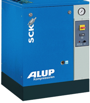
The video shows screw compressors from ALUP
Conclusion
Air compressors are not the best cheap option for purchase, but a worthy competitor to other types in terms of performance.
They are much more profitable in terms of the total cost of maintenance, energy, repairs, workers and are able to justify their price even before the end of the operating period. For large volumes of work, the rotary type of equipment is an economically reasonable solution.


Mixed Personality Disorder: Causes, Symptoms, Types and Treatments
GTA 4 control settings
FAQ on Smuggling in GTA Online
LSPDFR - welcome to the police
The huge map of Grand Theft Auto San Andreas and its secrets