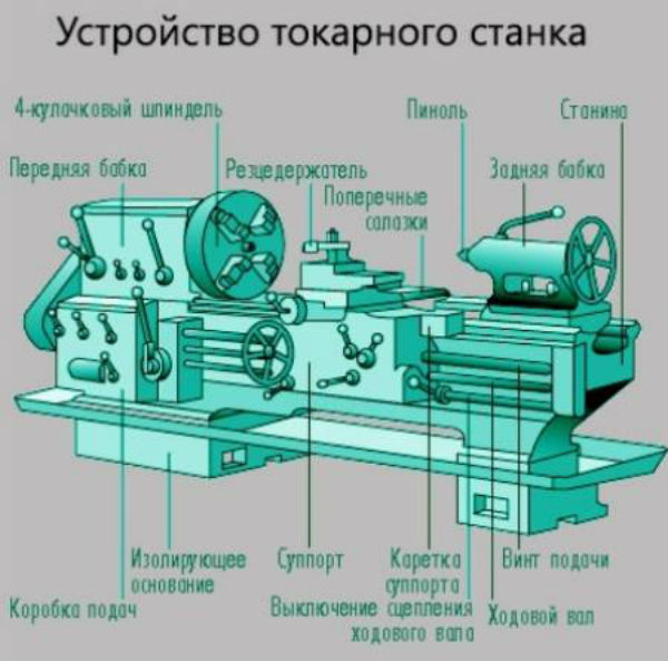
Lathes for metal, in their total mass, have approximately the same layout - the arrangement of nodes. In this article, we will list and describe the main nodes, the principle of their operation and purpose.
The main nodes are:
- bed;
- headstock;
- spindle;
- feed mechanism;
- caliper;
- apron;
- tailstock.

If you get to the point where your turning requirements exceed the Revo's capabilities, you didn't need to replace the lathe. You can purchase an optional bed extension that increases the span from 18 to an impressive 32 inches and spindle spacing to a whopping 56 inches.
The bed extension has a tool height extension that adds 7 to the height of the tool stop until you place the bottom level of the extension. While the bed extension is likely to be an accessory for future consideration, the halogen light accessory is one that fits into the "can't live without" category. Good lighting is, after all, essential to good work. on the headstock or tailstock, and it has a triple articulated arm that allows you to precisely position the bright white light exactly where you need it.
Video lesson on the device of lathes for metal
bed
The main fixed part of the machine is the frame, which consists of 2 vertical ribs. Between them there are several transverse crossbeams that provide rigidity and stability of the stator.
It is very well thought out and has the power and features to satisfy the most demanding woodworker. It is very convenient to have several of these accessories, which are very easy to make. It must be taken into account that if for some reason we need to pause the turn, it is not convenient to unscrew a piece from the slab, because when you want to place it again and continue it, it will need to be corrected, even if we have made location marks, since we it is almost impossible to stay in the exact previous position.
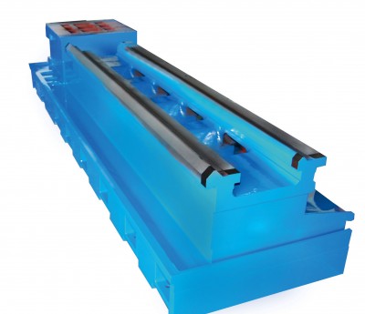
The bed is located on the legs, their number depends on the length of the bed. The design of the legs-curbstones is such that they can store the tools necessary for the operation of the machine.
The upper transverse rails of the bed serve as guides for moving the caliper and tailstock along them. Comparing the schemes of machine tools, it is easy to see that in some designs 2 types of guides are used:
Description of lathe spindle
This is why it is necessary to have "spare" inserts in order to be able to make several pieces at the same time, and also to use them with a grinding disc. Thus, the "pressed" nut is welded so that it does not move. There is no need for a full seam like in my utensils, two or three stitches on each side of the nut is sufficient and try to avoid warping due to excessive heat.
You make 5, 6 or more ground holes and remove all burrs with an angle grinder. If there are no beats and the instrument gently touches the plate, it's that the Tote Gods are smiling at us and the cymbal was good on the first try, something else unlikely.
- prismatic for moving the caliper;
- flat guide for tailstock travel. In very rare cases, it is replaced by a prismatic type.
Headstock
The parts located in the headstock serve to support and rotate the workpiece during its processing. Here are the nodes that regulate the speed of rotation of the part. These include:
Drive shafts and mechanisms
If the centering was done carefully before welding and the discs are not deformed, they will be less than the difference in mm. easy to improve. It is clear that this whole procedure is extremely dangerous and 100% homemade, and that it is ideal to correct these dishes in a mechanical lathe. But it is good to be clear that it is not necessary that they remain perfect, since in them you always have to screw a disk of intermediate or "sacrificial" wood, which is turned to face it with a chisel, and it is on this disk that the piece is stuck in the turn, which saves any not very serious defect of the metal plate.
- spindle;
- 2 bearings;
- pulley;
- gearbox responsible for adjusting the speed of rotation.
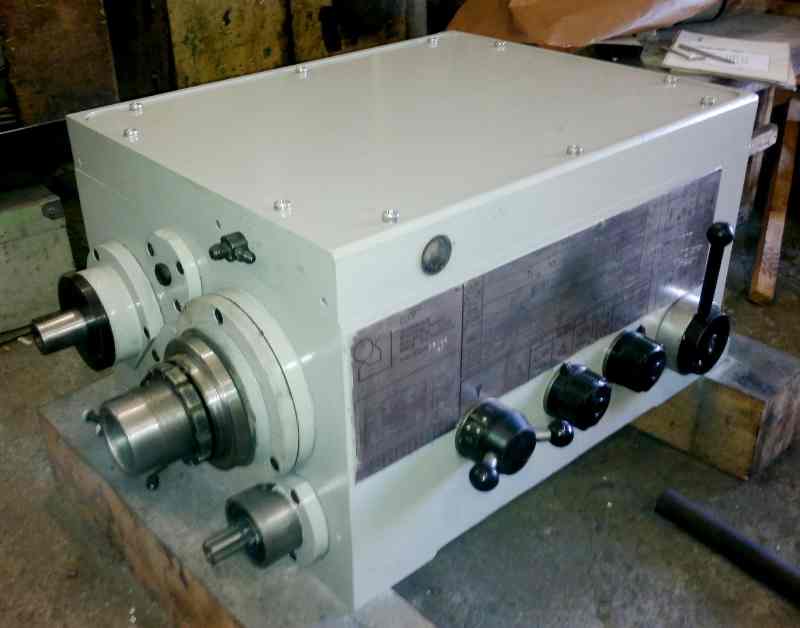
The main part of the headstock in the device lathe- spindle. On its right side, facing the tailstock, there is a thread. Chucks are attached to it, holding the workpiece. The spindle itself is mounted on two bearings. The accuracy of the work performed on the machine depends on the condition of the spindle assembly.
In the photo you can see one of the homemade dishes screwed to a wooden disc with sandpaper. The other is with a sacrificial disc made of poplar. Another large wooden sandpaper disc has a wooden "nut" attached to it for screwing directly to the shaft without the use of metal plates. The towing lug is a 1" nut that uses an angled grinding machine and the dremel made three ribs, and inside a piece of threaded rod in the tip stuck with epoxy putty.
If you want to add something to the topic, comment or ask a question, feel free to do so. Today we will learn how to make our own homemade wood lathe. Now we will prepare the same width and we will place it at the top. We have to glue it with wood glue.

Gearbox top view
In the headstock there is a guitar of interchangeable gears, which is designed to transmit rotation and torque from the output shaft of the gearbox to the shaft of the feed box for cutting various threads. Caliper feed adjustment is carried out by selecting and rearranging various gears.
Restoration of the tailstock with acrylic
Now we will go to a distance of 7.5 cm and insert the second tape in parallel. Something like this should be something like this. This piece, anger, placed on the motor shaft. Once we cut, we have to drill a hole on one side and 3 small holes on the other side. Now we place the contact adhesive on the motor shaft and we insert it into the piece with the face having one hole.
For the other side that we made, 3 small holes, we will do the following. take a nail and with a saw cut off from the tip about 6 or 7 mm. We have to repeat the operation until you have exactly 3 equal points. The next thing to do is place the contact adhesive inside the holes and very carefully present each of these tips in this way.
Guitar of interchangeable gears of the Optimum lathe Guitar of the Soviet lathe for metal
It is unlikely that you can still find a metal lathe device with a monolithic spindle. Modern machines have hollow models, but this does not simplify the requirements for them. The spindle housing must withstand without deflection:
At the same time, we will make a headdress. We already have a ready leader. Now, a little with the same bearing diameter, we will make a small hole right in the center, and with another small piece we will deepen it. This hole should stay like this. that we can place this piece, which is nothing but one of the screws crossing the bearing.
Lathe marking
With a marker, we mark 2 centimeters, and later, with a saw, we cut through the mark. With a little polisher or file, we shape the tip until you get something like this. Now we just need to make a small piece like this one with a center break line that we will place right behind the last one we made and stick with glue. For the last one, we just need to make some holes in the back of the base, right in the center of the rail, which we will separate 3 centimeters apart.
- parts with a large weight;
- maximum belt tension;
- cutter pressure.
Special requirements are imposed on the necks on which they are installed in bearings. Grinding them must be correct and clean, surface roughness is not more than Ra = 0.8.

The purpose of this is to skip the screw from below. Finally, you only need to attach the engine head to the base using wood glue. And adjust the counterpoint, that is, the opposite part, to the desired distance. To place the wood you want to cut, remember that you must have 3 small holes so that you can fit in well. You already know that if you want to appear in the next one, you must leave your comment in the same video. In the category we called "semi-professionals", we included lathes, which, like hobbies, became mass-production shop makers.
In the front part, the hole has a conical shape.
Bearings, spindle and axle must create a single mechanism during operation, not having the ability to create unnecessary beats, which can be obtained by improper boring of the hole in the spindle or careless grinding of the necks. The presence of play between the moving parts of the machine will lead to inaccuracies in the processing of the workpiece.
Tailstock for metal lathe
Therefore, instead of quality and technology, features that make work more comfortable. It follows that they do not have to cope with a higher workload, but they are close to a professional team. We include lathes in this category that offer free hands at work in the desktop lathe category and prices. Their designation is called 450 or 460.
Casting consists of a cast bed with a cast headstock. The horseshoe and support are also castings. Strengthening the tailstock and backrest is carried out with the help of eccentrics. Frequency transmissions typically change by 5 degrees. pulley. It usually comes with basic accessories: 4 prong drive, swivel tip, faceplate.
Spindle stability is provided by bearings and a preload adjustment mechanism. It is attached to the right bearing by means of a bored, neck-shaped, bronze bushing. Outside, its bore coincides with the socket on the body of the headstock. The sleeve has one through hole and a few notches. The bushing is fastened in the socket of the headstock with nuts screwed onto its threaded ends. The bushing nuts are used to adjust the split bearing preload.
Opinions and Experience: A nice little lathe with the ability to quickly change the position of the support or tailstock thanks to the final smooth speed control of a fairly robust motor. Engine Location - Hold on to it and drop it on the sawdust, it's placed under the most preferred part.
The motor power matches the size of the lathe. The base, as stated, allows you to rotate between the spikes or turn simple plates attached to the board with screws. For further work it is recommended to look for additional accessories.
The gearbox is responsible for changing the speed of rotation. To the right of the pulley, a gear is attached, to the right of the pulley, the gear is mounted on the spindle. Behind the spindle there is a roller with a freely rotating sleeve with 2 more gears. Through the neck, the roller fixed in the brackets, rotational motion is transmitted. Different size gears allow you to vary the speed of rotation.
Short Description: Nice advanced desktop lathe will satisfy even more demanding users and more advanced lathes. To work on smaller things, it will also satisfy the professional. These lathes already show technical specifications that make it difficult to stop.
Lathes are made on one belt, only the color of the machine or some minority. The substrate is made of castings. The speeds are mainly changed by stepless speed control. The machines are equipped with a digital speed indicator. It usually comes with basic accessories: 4 prong drive, rotating tip, faceplate.
The enumeration doubles the number of working speeds of the lathe. The structure of a metal lathe using enumeration allows you to select an average speed between the base ones. To do this, just throw the belt from one gear to the next or set the lever to the appropriate position, depending on the design of the machine.
The speed change system is not suitable for everyone - mosquito infestation. dust collector and its subsequent shutdown - the stock can only be rotated 90° or 180°. On newer lathes, the base is made from castings, greatly increasing the rigidity of the machine and giving it a solid construction. It is pleasant to work on and the machine runs smoothly. Thanks to the possibility of acquiring various accessories, not only "branded", the machine is a good starter model for small items.
A copier can be purchased for these lathes. The base accessory also includes an additional support arm that is designed to work on a 90° head to remove for normal operation to prevent weft picking. Rotating the spindles 180° or moving them around the bed gives you better access to front work when turning cavities.
The spindle receives rotation from the electric motor through a belt drive and a gearbox.
Feed mechanism
The feed mechanism tells the caliper the desired direction of movement. The direction is set by the snaffle. The snaffle itself is located in the headstock housing. It is controlled by external handles. In addition to the direction, you can also change the amplitude of the movement of the caliper using interchangeable gears of a different number of teeth or a feed box.
In the scheme of machines with automatic feeding there is a lead screw and a roller. When carrying out high-precision work, a lead screw is used. In other cases - a roller, which allows you to keep the screw in perfect condition for longer for complex elements.
The upper part of the caliper is the place of attachment of the incisors and other turning tool necessary for the processing of various parts. Due to the mobility of the caliper, the cutter moves smoothly in the direction necessary for processing the workpiece, from the place where the caliper with the cutter was located at the beginning of work.

When machining long parts, the travel of the support along the horizontal line of the machine must match the length of the workpiece being processed. This need determines the ability of the caliper to move in 4 directions relative to the center point of the machine.
Longitudinal movements of the mechanism occur along the sled - the horizontal guides of the frame. The cross feed of the cutter is carried out by the second part of the caliper, moving along vertical guides.
The cross (lower) slide serves as the basis for the rotary part of the caliper. With the help of the rotary part of the support, the angle of the workpiece relative to the apron of the machine is set.

Apron
The apron, like the headstock, hides behind its body the nodes necessary to set the machine mechanisms in motion, connecting the caliper with the gear rack and lead screw. The control knobs of the apron mechanisms are placed on the body, which simplifies the adjustment of the caliper travel.
The tailstock is movable, it is used to fix the part on the spindle. It consists of 2 parts: the lower one - the main plate and the upper one, holding the spindle.

The movable upper part moves along the lower one perpendicular to the horizontal axis of the machine. This is necessary when turning cone-shaped parts. A shaft passes through the wall of the headstock, it can be turned by a lever on the back of the machine. The headstock is fastened to the frame with ordinary bolts.

Each lathe is individual in its layout, the device and circuit may differ slightly in details, but in small and medium-sized machines this option is most common. The layout and schemes of heavy large lathes differ depending on their purpose, they are highly specialized.
If you find an error, please highlight a piece of text and click Ctrl+Enter.
The emergence of a large machine park, consisting of mechanisms various types and modifications, made it possible to automate the process of processing metal products to one degree or another. Lathes are one of the most common not only in production.
There are also on sale that do not have such capabilities as their "adult" counterparts, but, nevertheless, they are successfully used in everyday life or in small specialized workshops. Let's talk about how the machines for the production of turning work are arranged.
According to the classification metal cutting equipment, lathes belong to the 1st group. All of them differ in the specifics of technological operations, accuracy and a number of other parameters. Hence, there are some differences in the design of individual elements, as well as in the configuration. Therefore, below is only general information on the design of lathes designed for processing metal products.
Lathe design
Consider the example of a revolving model as the most common. Everything is clearly visible in the figures, so separate explanations will suffice.

Spindle (front) headstock, depending on the model and manufacturer, is made of cast iron or sheet (but thick) iron. On it, in addition to the spindle itself, there is a speed switch.
For a better understanding of the device, you should understand why and how this happens. The practice of operating lathes shows that this is one of the weakest points of any unit. By design, this part of the machine is not much different from the manual gearbox of a car. Inside - a set of gears mounted on axles located at different levels.
The combination by which they are connected to each other determines the speed of rotation of the spindle. On semi or fully automated machines, this parameter is set with a switch. Depending on the position of its lamellas, a voltage of +24 V is supplied to the control element - an electric / magnetic clutch, the operation of which allows you to switch from one mode to another.
The quality of turning work is significantly affected by the backlash of the spindle. As a rule, it is a consequence of the limiting development of one of the bearings - front or rear. Sometimes both need to be replaced.
caliper
It has a holder mounted on it. Its movement to the right-left can be carried out mechanically or manually.
Components of a lathe
- Carriage.
- Cross slides.
- Cutter holder.
- Apron. The execution of this constructive part different models can be very different.
- Slides are incisive.
tailstock
It performs a dual function. If a metal sample is fixed in the spindle, and a drill is in the tailstock, then the drilling operation can be performed by moving the carriage to the left. Having fixed the end of the overall metal blank in this part of the machine, it will be possible to carry out the corresponding turning work. In this case, the machining tool is a cutter, which the turner “leads” in the direction he needs.

Some designs of tailstocks have not the usual (traditional), but a rotating core. This allows you to increase the speed of turning work.
Box with automation elements (it is not available on manual machines)
It contains a motor, a transformer and a number of controls (start / stop button, warning lights, and so on). More modern models, belonging to the heavy category, are equipped with an electric cabinet.
All circuits of lathes are designed for low voltages (from 12 to 36 V). This is due to the fact that a probable breakdown of the insulation of the 220 V circuit (and all parts of the equipment are metal) will lead to the most unfortunate consequences.
Types of lathes
The classification is rather complicated, since it is carried out according to several parameters (type of work, degree of automation, weight, etc.). Therefore, only a general overview of the most famous varieties.

- Semi- and automatic.
- Single or multi-spindle.
- Revolver.
- Screw-cutting.
Multi-cutting

carousel

backing

Lathe marking
It is alphanumeric. The decoding of positions (from left to right) in the designation of products is as follows.
- 1st (number). For lathes - always "1".
- 2nd (number or letter). Type of equipment. For example, for a carousel machine this is “5”, for a windshield machine it is “6”, for a screw-cutting machine it is “I”.
- 3rd (number). Main parameter (in dm). It is usually taken as the height of the centers.
- 4th (letter). It is not always displayed. Indicates the features of a lathe. For example, the letter "T" indicates that it is modified; "P" - increased accuracy, and so on.

Main characteristics
Each lathe has its own capabilities. What to pay attention to first of all?
- The maximum cross section of a workpiece that can be clamped in the spindle.
- The distance between the centers of attendants at their extreme position. This determines the maximum length of the sample that can be processed.
- Limit thickness metal part. It is determined by the distance from the axis of the spindle - tailstock to the caliper.
There are quite a few modifications of lathes, but if you delve into their design, then there are no fundamental differences. The main difference is in the layout of the machines, the location of some nodes and their design (shape, dimensions, etc.). For each product, the manufacturer must attach a set of documentation, according to which, having general concept about the device of a lathe, it will not be difficult to deal with the nuances.


History of sky lanterns
Job description: concept, purpose, structure, procedure for compiling and formalizing Purpose and content of job descriptions for managers
Interview questions What job are you going to work on?
What to do if the boss criticizes all the time If the boss does nothing
How to understand: will the kitten be fluffy?