On the screw-cutting lathe simple principle of operation: the workpiece, which is clamped in a horizontal position, begins to rotate and the cutter, which is movable, is not removed desired material. But in order to implement this principle, a mechanism is needed, which consists of a large number precisely matched elements. Lathes unite nine types of machine tools, which differ in various ways: in design layout, in purpose, in degree of automation.
The use of special additional devices on machines (for milling, for grinding, for drilling radial holes) greatly expands the technological functionality of the equipment.
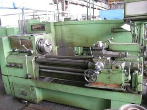
Lathes, automatic and semi-automatic, are divided into vertical and horizontal, depending on the location of the spindle, which carries a fixture for setting the workpiece of the part that is being processed. Vertical machines are mainly used for processing parts of large dimensions and weight, but of small length. The most famous lathes in the times Soviet Union- 16K20 and 1K62. The lathe is designed to process materials by cutting in order to obtain parts in the form of bodies of revolution. Today there are several main types of lathes. The most universal technique turning group is screw-cutting lathes used in small scale production. And screw-cutting lathes, in turn, are also divided into types:
Screw-cutting lathe device
Screw-cutting lathe has its own device. The main body of the equipment is fixed, and the tool starts its work by pressing special heads. The part that is obtained during the processing can be used in such operations. Now many people believe that the use of a screw-cutting lathe is not optimal. The processing of materials can be increased and carried out with greater efficiency. But the element received by manufacturers after work is usually satisfied.Screw-cutting lathe - axes
Axis screw-cutting lathe This is fairly new equipment. But, nevertheless, he has already managed to gain popularity among specialists in the industrial sector. The axis lathe, otherwise known as RAM, combines the features of conventional lathe tools with an axis style quill.On the lathe of this type, the principle of operation is quite simple and understandable even to those people who have never encountered industry. At the moment when the equipment is joined to the workpiece to be processed, it begins to slide on its surface. And so the processing becomes fast, easy, and of high quality.
CNC screw-cutting lathe
This machine is able to replace the old type of equipment. The multi-spindle and other CNC tools have a number of advantages: they are easy to install and easy to operate. This technique fully meets the trends of today's development of jobs.
The performance of CNC screw-cutting lathes is much higher than others existing types equipment this class. It can be noted that organizations that purchase such machines solve their productivity problems one hundred percent. A screw-cutting lathe can easily be considered the most universal machine from all existing machines of the turning group. It is used in the conditions of small-scale and single-piece production of various parts. Now, due to its versatility, it is in great demand in many organizations that work in the metalworking industry.
Lathes allow you to process internal and external surfaces. The technique makes it possible to grind parts of various shapes (shaped, conical, cylindrical), perform drilling, boring, reaming holes, trimming ends, knurling, threading and other operations. Also, the possibility of using special equipment will give you the opportunity to perform other work. For example, you can carry out milling, grinding, cutting teeth and others.
Screw-cutting technology, first of all, it is intended for single and small-scale production. But, if necessary, it can be equipped with additional devices and devices that will make it possible to expand to mass production. In mass production, turning and revolving semi-automatic machines and automatic machines are used. Maintenance of the machine involves periodic adjustment, supply of material to the machine and control of the workpieces.
In a semi-automatic machine, the movements associated with the removal and loading of blanks are not automated. Automatic workflow management of such screw-cutting lathes is carried out thanks to the camshaft where the cams are installed.
Any screw-cutting lathe (desktop, universal, CNC) is an equipment with which turning of metal products and other materials is performed.
1 The device of a screw-cutting lathe - the main components and mechanisms
Universal screw-cutting lathes make it possible to carry out such types of metalworking operations as:
- reaming holes;
- turning and boring of shaped, conical, cylindrical surfaces;
- reaming;
- processing and trimming ends;
- thread cutting;
- drilling.
All machines of this group have an identical device. Their main assembly units are the following nodes:
- caliper;
- front and;
- gearbox;
- bed;
- spindle;
- electric starting equipment;
- cabinets;
- guitar gears of interchangeable type;
- running roller;
- apron;
- gearbox;
- lead screw ( it is its presence that distinguishes a screw-cutting turning unit from a conventional turning).
It is noteworthy that all the constituent elements of the machines under consideration not only have the same purpose and name, but are also located in the same places.
This means that the 16K20 unit, produced by the Krasny Proletarian plant in the 1970s, and from the Chelyabinsk Stankomash OJSC are similar to each other, like two brothers. Even the scheme of a screw-cutting lathe with a numerical program management(for example,) differs from older models only in the presence of this same CNC.
In addition to the main units, the units of the screw-cutting group have a number of control handles with which the operator performs his work on the machine. The following handles are available:
- changes in spindle speed;
- setting the pitch and feed of the thread being cut;
- installation of increased or normal thread pitch;
- movement (longitudinal and transverse) of the sled;
- movement of the upper slide;
- start and disable the lead screw (its nuts);
- choice of the direction of thread execution (right- or left-hand);
- start and stop the main electric motor;
- quill fixation;
- start automatic longitudinal feed;
- movement of the quill (this handle is usually called the steering wheel);
- start and stop feeding;
- switching the caliper to the mode of rapid movement;
- fixing the tailstock;
- stopping the spindle and changing the direction of movement of this element of the machine.
2 Principles of classification of aggregates of the screw-cutting group
The described equipment is divided into several types according to three technical characteristics:
- machine weight;
- the maximum length of the product that can be processed on a particular unit;
- the maximum diameter of the part that the machine can handle.
The longest workpiece length that can be machined depends on the spacing between the centers of the lathe. The range of maximum processing sections for the equipment we are considering starts with a diameter of 100 millimeters and ends with a diameter of 4,000 millimeters. It is important to know that different machines same indicator allowable section of the workpiece are often characterized by different values of the length of the workpiece.
By weight, all screw-cutting equipment is divided into four classes:
- up to 400 tons - heavy machines (the largest diameter of the part for processing in them is 1600–4000 mm);
- up to 15 tons - large (diameter varies from 600 to 1250 mm);
- up to 4 tons - medium (from 250 to 500 mm);
- up to 0.5 tons - light (from 100 to 200 mm).
Light machines are usually understood as their desktop modifications used by home craftsmen for private purposes and small businesses:
- experimental and experimental sections of plants;
- watch companies;
- instrument companies.
Heavy and large units are usually used in power and heavy engineering. They are also used for special processing of various mechanisms:
- turbine rotors;
- wheel pairs of railway cars;
- elements in metallurgical plants.
Most of the turning operations are performed on installations related to middle group. They account for about 80 percent of all metalworking work. They allow you to carry out semi-finishing and finishing operations, to cut threads of various nature.
The design of such machines is characterized by a large range of feeds of the working tool and spindle speeds, sufficient rigidity. They are equipped with electric motors of acceptable power, which makes it possible to process metal and other products in very economical modes using tools made of superhard alloys and hard materials.
In addition, medium-weight units are supplied with a variety of special devices in order to expand their technological potential. Such "bells and whistles" increase the quality of workpiece processing on turning units and facilitate the work of turners. Due to these devices, the machines become many times more automated and convenient to use.
Lathes with program control (CNC) in the USSR were made quite actively. The production of such machines was carried out by the Leningrad plant (model LA155), Kuibyshev (16B16) and others. CNC units are usually used by large enterprises for multi-operational processing of a large range of products, which are produced in small batches (no more than a couple of hundred pieces). The high repeatability of metalworking and short changeover times make CNC machines indispensable in this situation.
3 Common methods of working on machines of the screw-cutting group
Most often, turning equipment produces processing (using through cutters) of cylindrical external surfaces. In this case, the part is inserted into the cartridge with an allowance of 7 to 12 millimeters (it is understood that the required length of the product will be less by exactly the specified value). The need for such a "reserve" is due to the fact that the turner will need to cut off the finished workpiece, as well as process its ends.
![]()
For trimming the end, use persistent or straight through, as well as trimming cutters. The metal layer is removed from the end surface by moving the through cutter in the transverse direction. If a scoring tool is used, the part is machined from its center in the longitudinal direction. To perform the operation of trimming and turning small ledges on the product, a thrust cutter is usually used.
When a screw-cutting lathe performs a grooving procedure on the outside of a workpiece, the operator uses special grooving tools. They work with them at low speeds (compared to the procedure for trimming the ends, the spindle speed is set 4–5 times lower). At the same time, the grooves are cut without any effort, as smoothly and softly as possible.
By a similar principle, the cutting of the finished product is carried out. This operation is completed at the moment when the section of the bridge on the workpiece is about 2.5 millimeters. After that, the unit stops, the cutter is removed from the slot, and then the product simply breaks off.
The screw-cutting lathe (TVS), before becoming what it is today, has come a long way of evolution. With each stage of development, this type of equipment changed in size, the power of the units grew, the functionality expanded, the parameters of accuracy, ergonomics and a host of other indicators improved.
Interestingly, the principle of operation of this technique has not actually changed since its invention. The device of a screw-cutting lathe is unchanged in the global sense of the word, as well as its fundamental components. The basic principles of working on this technique have also been preserved.
Let us consider in more detail what this equipment is, without which it is impossible to imagine not only individual industrial structures, but also entire sectors of the economy.
The essence of the work of TVS is quite simple and logical. The fixed part rotates along the longitudinal axis. This process is called the main movement. In turn, the tool is brought to the part and makes a transverse and translational stroke. Such manipulations allow you to remove part of the workpiece in the right places to obtain the finished part.
Home distinctive feature screw-cutting lathe from a conventional turning unit it is considered that its design provides for the presence of a special lead screw, which makes it possible to very accurately create new thread from the outside of the workpiece.
Key components of the unit
Screw-cutting lathes consist of several large units. The bed is the fundamental part of the machine, where all its other components are fixed. The bed is made of very strong cast iron. A heavy base with several guides at the top is a design that has proven itself many years ago. That is why manufacturers of screw-cutting lathes do not change this time-tested format. The guides move the tailstock and caliper.
Another important node in the design is the headstock, where the spindle is located, equipped with a chuck for fixing the workpiece. Also on the headstock there is a gearbox that transmits the rotation from the electric motor to the spindle.
The support is important element to feed the cutting tool. The design includes a special carriage, tool holder and apron. The tool holder is needed to fix the tool. The carriage moves the tool along the guides.
The design of the apron includes caliper control mechanisms and special slides that move directly along the apron in the longitudinal and transverse directions. The drive to the apron reports the feed box. The guitar built into the box makes it possible to adjust the thread pitch. The tailstock acts as a workpiece holder custom sizes. In addition, a tool is located on it, whether it be drills, reamers or countersinks.
It should be noted that this design of a screw-cutting lathe is considered a standard equipment for this type of equipment. This does not preclude the presence of optional nodes. In recent years, many manufacturers have equipped equipment with copying mechanisms and special milling nozzles, which significantly expands the functionality of a traditional unit.
Moreover, CNC screw-cutting lathes are a serious competitor to standard models. By the way, the latter are characterized by increased productivity, accuracy and ease of use.
Depending on the device of the screw-cutting lathe, it is possible to classify this equipment according to a number of features. This may be the degree of automation of workpiece processing processes, design features unit and intended purpose of a particular model.
Today, a rough division of this technique can be its classification into automatic and semi-automatic. Also, screw-cutting lathes are of horizontal and vertical type. It depends on where the spindle is located. Vertical type units are used when there is a need to process short, heavy parts.
One of the most important parameters that the master needs to pay attention to when choosing a machine is the level of load on the moving structural elements. The weaker each individual part of the machine, the higher the likelihood that the equipment will often fail and stand idle. This is especially true for those who use non-new technology.
Even after years of active use, the rigidity of the frame must remain at its original level, and each node must perform its function flawlessly. Only in this case can we talk about the high performance of the unit at the limit of its capabilities.
Today, screw-cutting lathes will please with high accuracy, incomparable with the units produced in the middle of the last century. The tools that this technique is equipped with are made from high-quality hard alloys of excellent strength. Almost all modern machine tools are the standard of accuracy and productivity. All this once again confirms that, although this technique has not changed so much outwardly, its performance characteristics progress every year.
conclusions
Screw-cutting lathes are equipment that is in stable demand in Russia. Today, the master has a huge selection of new and used units. Domestic manufacturers of such equipment fully meet the needs for it. At the same time, they also have serious competitors, especially among Asian and European brands.
Be that as it may, Russian manufacturing companies have everything to create high-quality competitive equipment. Affordable prices, high quality components and efficient engineering developments make this technique very popular in the post-Soviet space.
The purpose of the work: to study the general device of a screw-cutting lathe, tools, fixtures and types of work performed on the machine; learn to determine the machine time when turning.
Workplace equipment
1. Screw-cutting lathe.
2. A set of turning tools.
3. Attachments for a screw-cutting lathe.
4. Guidelines.
I. The device of a screw-cutting lathe
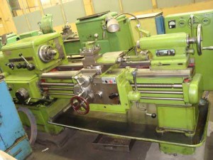
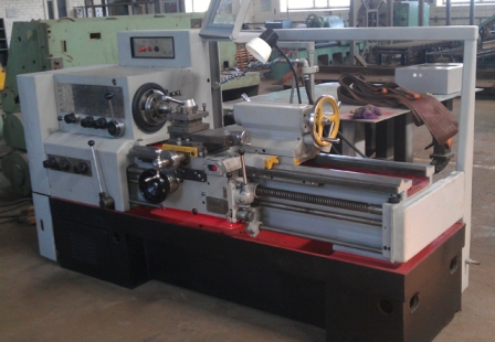
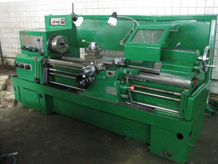
Screw-cutting lathes are high-performance and most common machines. The machine is designed for processing various metals and non-metal materials. All types of turning operations are performed on the machine: turning of external and boring of internal cylindrical and conical surfaces, cutting, drilling, countersinking and reaming holes, cutting various threads, etc. Using a hydrocopier on the machine, you can perform turning and copying work. Screw-cutting lathes, according to the classification of metal-cutting machines, belong to group I, type 6 (for example, machine model 16K20).
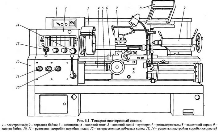
On fig. 2.1 shows a diagram of a screw-cutting lathe.
For the installation of all machine components, a frame 2 with longitudinal prismatic guides is used. The bed is fixed on the pedestals. In the left pedestal I, the electric motor of the main drive of the machine is mounted, in the right pedestal 12 - a tank for coolant and a pumping station. The headstock 6 is installed on the frame above the front pedestal. The machine speed box and the hollow spindle are mounted in the headstock. Mechanisms and transmissions of the gearbox allow you to get different speeds of the spindle, thereby ensuring the speed of the main movement (V). On the spindle, fix the clamping devices (cam chuck, driver chuck, plan-washer) to transmit torque to the workpiece being processed. On the front side of the headstock there is a control panel for 5 gearbox mechanisms.
5 6 7 8 9 10 11
Rice. 2.1. Scheme of a screw-cutting lathe
On the front side of the bed, under the headstock, a feed box 3 is attached. Mechanisms and gears are mounted in the box, allowing you to get different speeds of movement of the calipers. The feed box receives rotational movement from the gearbox with the help of interchangeable gears, called a guitar, located on the left end side of the frame in box 4.
A longitudinal support 7 moves along the guides of the frame, providing a longitudinal feed to the cutter (S pr). A transverse carriage moves along the guides of the longitudinal support perpendicular to the axis of rotation of the workpiece, on which the upper support 9 is mounted. The transverse carriage provides a transverse feed to the cutter (S p). The upper rotary support can be set at any angle to the axis of rotation of the workpiece, which is necessary when machining conical surfaces.
A four-position rotary tool holder 8 is mounted on the upper support, in which four cutters can be installed simultaneously. An apron 10 is attached to the longitudinal support. Mechanisms and gears are mounted in the apron that convert the rotational movement of the lead roller or lead screw into the translational movement of the calipers. The running roller (with a longitudinal splined groove) and the running screw (with an external thread) are located along the frame and receive rotational movement from the feed box. The apron mechanism is designed in such a way that the movement of the caliper can be carried out either from the lead roller for smooth turning, or from the lead screw for threading.
The tailstock 11 is installed on the right side of the frame and moves along its guides. The tailstock quill can be equipped with a rear center or a tool for processing holes (drills, countersinks, reamers). The body of the tailstock is displaced relative to the base in the transverse direction, which is necessary when turning the outer long conical surfaces.
To provide normal conditions work, the machine is equipped with individual lighting and a special protective screen that protects the worker from injury from falling chips.
Screw-cutting lathes have the following fixtures and accessories: chucks, centers, driving chuck, steady rests and copy rulers.
Laboratory work
Production and industrial technologies
Rice. Screw-cutting lathe The main components and movements of the machine 16K20 In the headstock 1 fig. Brief technical specifications machine The largest diameter of the workpiece to be machined above the bed mm 400 The largest diameter of the workpiece to be machined above the lower support carriage mm 220 The largest diameter of the machined bar mm 53 The largest length of the workpiece to be machined mm 71010001400 Spindle speed min1 1251600 Number of spindle speeds 22 threads:...
The device of a screw-cutting lathe, work performed on it, accessories and tools
Objective: to study the device of a screw-cutting lathe and the purpose of its main components and parts; get acquainted with the cutting tools used to perform various turning operations; Familiarize yourself with the types of turning and the accessories used for this.
Equipment. Screw-cutting lathe mod. 16K20; turning tools, drills, countersinks, reamers, taps, dies; cartridges, centers, lunettes;
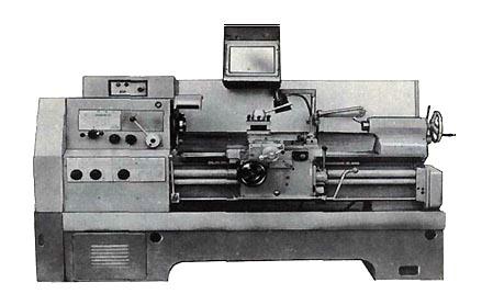
Universal screw-cutting lathe mod.16K20 is designed for processing workpieces in the form of bodies of revolution, as well as for cutting various types threads
Fig.1. Screw-cutting lathe
The main components and movements of the machine 16K20
In the headstock 1 (Fig. 1), placed spindle and gearbox.,designed to change the frequency and direction of rotation of the spindle with the workpiece. tailstock 2 supports the workpiece when working in centers and serves to secure instrument, processing hole(drills, countersinks, reamersetc.). When changing the length of the workpiece tailstock move along the guides. Caliper 3 carries a tool holder with a cutter and informs it of a longitudinal or transverse movement along the axis of the workpiece. Apron 4 is designed to transmit movement to the caliper from lead screw 5 or lead shaft 6 in the longitudinal and transverse directions. Gearbox 8 regulates the feed and turns on the lead screw.
On the bed 7 mounted the main components of the machine. When processing on a lathemain movement is an spindle rotationwith preparation. When turning a cylindrical surface, the caliper carriage with a cutter has a longitudinal feed, and when the caliper slide is moved,cross feed. When cutting the end surface, the transverse feed becomes a continuous movement, and the longitudinal one serves to periodically plunge the cutter into the workpiece. Atthreading main movement and longitudinal feed movement constitute a complex shaping movement.
The guitar of interchangeable gears 9 is used to set up the machine when cutting various types of threads with a cutter.
Brief technical characteristics of the machine
The largest diameter of the processed workpiece
above the bed, mm 400
The largest diameter of the workpiece being processed
above the lower caliper carriage, mm 220
The largest diameter of the processed
bar, mm 53
The greatest length of the processed
blanks, mm 710,1000,1400
Spindle speed, min-1 12,5-1600
Number of spindle speeds 22
Submission, mm/rev:
longitudinal 0.05-2.8
transverse 0.025-1.4
Cut threads:
metric, pitch in mm 0.5-112
inch, number of threads per 1 inch 56-0.5
modular, step in modules 0.5-112
pitch, in pitches 56-0.5
Spindle hole diameter, mm 55
Main motor power, kW 11
Main types of turning works
On lathes, turning cylindrical surfaces, trimming ends, turning external grooves, cutting off metal, drilling, reaming, countersinking, reaming, boring holes and internal grooves, centering, processing, "surfaces with shaped cutters, threading with dies, taps, cutters, thread rolling heads, processing of conical surfaces.
The main tools in turning are cutters. Depending on the nature of the processing, the cutters are rough and finish. Geometric parameters the cutting parts of these cutters are such that they are adapted to work with a large and small cross-sectional area of the cut layer.
According to the shape and location of the blade relative to the rod, the incisors are divided into straight ones (Fig. 2, a), bent (Fig. 2, b), and drawn (Fig. 2, c). In retracted incisors, the width of the blade is usually less than the width of the fastening part. The blade can be located symmetrically with respect to the axis of the cutter holder or be shifted to the right or left.
In the direction of feed movement, the cutters are divided into right and left. For right incisors, the main cutting edge is on the side of the thumb. right hand, if you put it on the incisor from above (Fig. 2, a). In the working movement, such cutters move from right to left (from the tailstock to the front). In the left incisors, with a similar imposition of the left hand, the main cutting edge is also located on the side of the thumb (Fig. 2, b). Such cutters in the feed move move from left to right.
 By purpose, turning tools are divided into through, boring, cutting, cutting, shaped, threaded and grooving.
To ensure the required accuracy and surface quality of the part while maintaining high labor productivity,
Left Right Left Right
Fig.2. Types of turning tools: a - straight
b - bent, c - curved, d - drawn
it is necessary to choose the correct geometry of the cutter. Plan angles play an important role here. The angles in the plan (Fig. 3) are the angles between the cutting edges of the cutter and the feed direction: φ is the main angle in the plan, φ 1 - auxiliary angle in plan, ε - angle at the top (ε = 180° - φ - φ one ). Angles φ and φ 1 depend on sharpening and installation of the cutter, and the angle ε depends only on sharpening. At a small angle φ, a large part of the cutting edge is involved in the work, heat removal improves, and the tool life increases. At a large angle φ, a smaller part of the cutting edge works, so the tool life decreases. When processing a long and thin workpiece, when there is a danger of its deflection, cutters with a large angle φ are used, since in this case the pressing force will be less. For shaping workpieces large diameter choose φ \u003d 30 - 45 °, for thin (non-rigid) - φ \u003d 60 - 90 °.
Auxiliary angle φ 1 is the angle between the secondary edge and the feed direction. If φ 1 small, then due to some pressing of the cutter, the auxiliary edge cuts into the machined
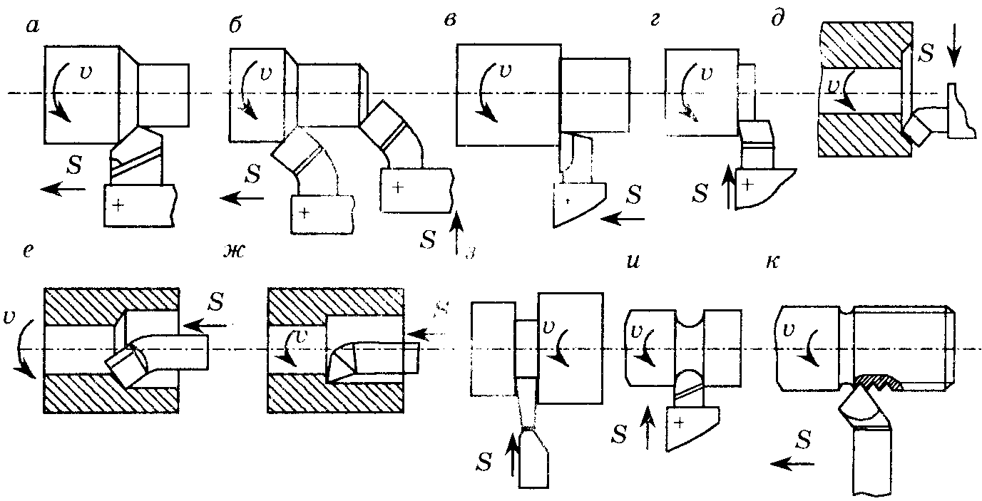
Fig.4. Types of turning tools: a - straight straight and b - through bent, v through-thrust, d, d - undercut, e - boring through passage, w - boring thrust, h - cutting, and - shaped, k - threaded
surface and spoil it. Large angle φ 1 unacceptable due to weakening of the incisor tip. Usually φ 1 = 10 - 30°.
Through straight lines (Fig. 5.5, a) and bent (Fig. 4, b) cutters are used to process external surfaces. For straight cutters, usually the main angle in the plan φ \u003d 45 - 60 °, and the auxiliary φ 1 = 10-15°. For through bent incisors, the angles in the plan φ \u003d φ 1 = 45°. These cutters work as pass-throughs during the longitudinal feed movement and as scoring cutters during the transverse feed movement.
For simultaneous processing of a cylindrical surface and an end plane, feedthroughs are used. persistent cutters(fig.4, v), working with longitudinal feed movement. The main angle in the plan φ = 90°.
Scoring cutters are used for cutting the ends of workpieces. They work with a transverse feed movement towards the center (Fig. 4, G) or from the center (Fig. 4, e) blanks.
Boring cutters used for boring holes, pre-drilled or obtained by stamping or casting. Two types are used boring cutters: through - for through boring (Fig. 4, e), thrust - for deaf (Fig. 4, g). They differ in the shape of the blade. For through boring cutters, the angle in the plan φ = 45-60°, and for thrust boring cutters, the angle φ is somewhat greater than 90°.
Cut-off cutters are used for cutting workpieces into pieces, cutting off the machined workpiece and grooving. They work with a transverse feed movement (Fig. 2, h). The cutting tool has a main cutting edge located at an angle φ = 90° and two auxiliary ones with angles φ 1 = 1-2°.
Shaped cutters are used for processing short shaped surfaces with a generatrix length of up to 30-40 mm. The shape of the cutting edge of the shaped cutter corresponds to the profile of the part. By design, such cutters are divided into rod, round, prismatic, and in the direction of feed movement - into radial and tangential. On the screw-cutting On machines, shaped surfaces are processed, as a rule, with core cutters, which are fixed in the tool holder of the machine (Fig. 4, and).
Threaded cutters (Fig. 5.5, j) are used to form external internal threads of any profile: rectangular, triangular, trapezoidal. The shape of their cutting blades corresponds to the profile and cross-sectional dimensions of the threads being cut.
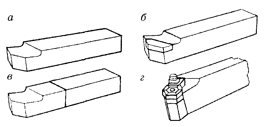 By design, one-piece cutters are distinguished, made from one workpiece; composite (with an integral connection of its parts); with soldered plates; with mechanical fastening of the plates (Fig. 5).
Fig.5. Types of turning tools but designs: solid(a, b) composite with soldered (in) or with mechanical fastening(d) plates
Toolholders are usually made from structural steels 40, 45, 50 and 40X with different sections: square, rectangular, round, etc.
Cutters with mechanically fastened carbide inserts have significant advantages over brazed cutters, since this design prevents the possibility of cracks in the inserts during soldering, and lengthens the service life of the mounting part of the cutter.
Multifaceted cutting inserts are made with three,four, five and six faces (Fig. 6). In order to create a positive angle on the front surface of the insert, holes and chamfers are made along the cutting edges by pressing followed by sintering.
The versatility of the metal cutting machine is extended by the use of accessories and fixtures. On a lathe, the main ones are: cartridges, centers (Fig. 7), lunettes. Auxiliary devices are also used: drill chuck, adapter sleeves, clamps.
Of the cartridges, the self-centering three-jaw chuck (Fig. 8) is most widely used. Its design provides simultaneous movement of three cams in the radial direction, due to which the workpiece is positioned along the axis of the spindle.
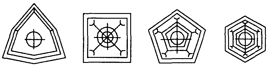
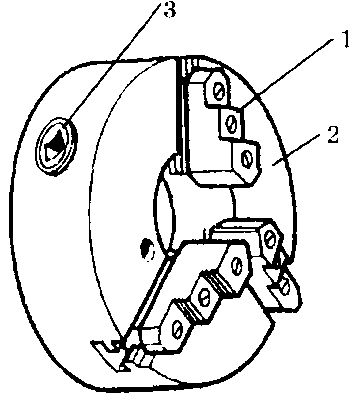 Fig.6. Multi-faceted inserts
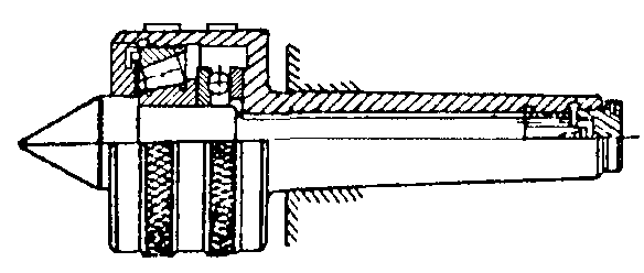
Fig.7. revolving center
Fig.8. Self-centering three-jaw chuck
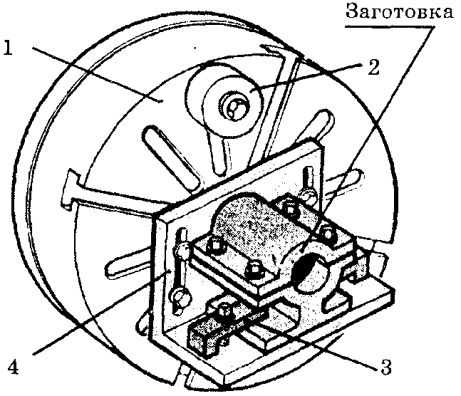 With an asymmetric section of the workpieces, when its correct fixing in three-jaw chuck impossible, a four-jaw chuck with separate jaw clamping or a faceplate is used (Fig. 9).
When processing in the centers, to impart rotation to the workpiece, use leash cartridges (Fig. 10). At outdoor processing long workpieces of small diameter, in order to prevent deflection, they use
Fig.9. Faceplate
fixed (Fig. 11, a) or movable (Fig. 11, a) lunettes.
 Conical surfaces on a lathe are processed in the following ways: with a wide turning tool, turning the upper slide,by shifting the tailstock body in the transverse direction and using a copier or tapered ruler.
Wide cutter (Fig. 12, a) usually short conical surfaces with a length of 25-30 mm are turned.
When processing conical surfaces by turning the upper support (Fig. 12, b), it is set at an angle,equal to half the angle at the top of the processed cone. Processing is carried out by hand. The angle of rotation is determined by the formula
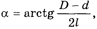
Fig.10. Processing in centers: 1 - driver chuck, 2 - front center, 3 - collar, 4 - rear chuck, 5 - tailstock quill
Fig.11. Processing long workpieces using a stationary(a) and movable (b) lunettes
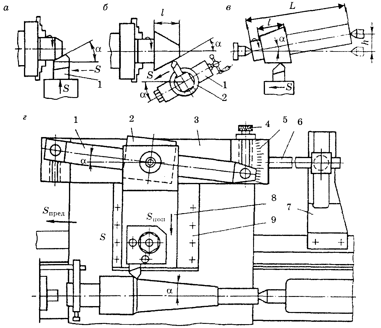
Fig.12. Ways of turning cones: a - with a wide cutter, b - turning the upper caliper, v - displacement of the tailstock body; G - using a conum ruler, 1 - rotary ruler, 2 - crawler, 3 - fixed ruler, 4 - screw, 5 - scale, 6 - rod, 7 - bracket, 8 - sled, 9 - housing
where D and d — diameters of processed conical surfaces, mm; l — cone height, mm.
By shifting the body of the tailstock in the transverse direction (Fig. 12, b), it grinds long conical surfaces with a small cone angle at the top (up to 12 °). At the same time, the displacement rear center in the transverse direction is determined from the expression
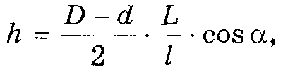
where L — the total length of the processed workpiece, mm.
The method of processing conical surfaces using a conical ruler (Fig. 12, G), attached to the machine bed, allows you to get conical surface with apex angle up to 40°. Processing is carried out with the inclusion of mechanical feed.
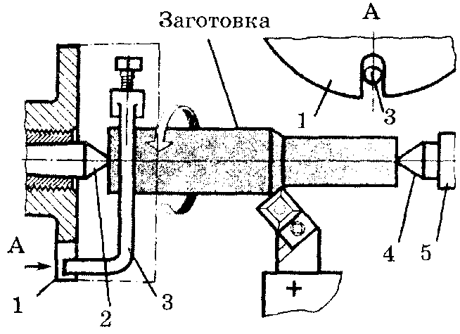
Depending on the shape and size of the workpieces, various ways their fastenings. When the ratio of the length of the workpiece to the diameter L/D < 4 заготовку закрепляют в патроне. При4 < L/D < 10 заготовку устанавливают в центрах, а при L/D >10 use steady rests.
A common method is processing in centers (Fig. 13), as it allows you to rearrange the part from machine to machine without subsequent alignment. At the same time, center holes are pre-drilled at the ends of the workpiece. The shape and dimensions of the center holes (Fig. 14) are standardized. When installed on the machine, the points of the centers of the front and tailstocks of the machine enter these holes.
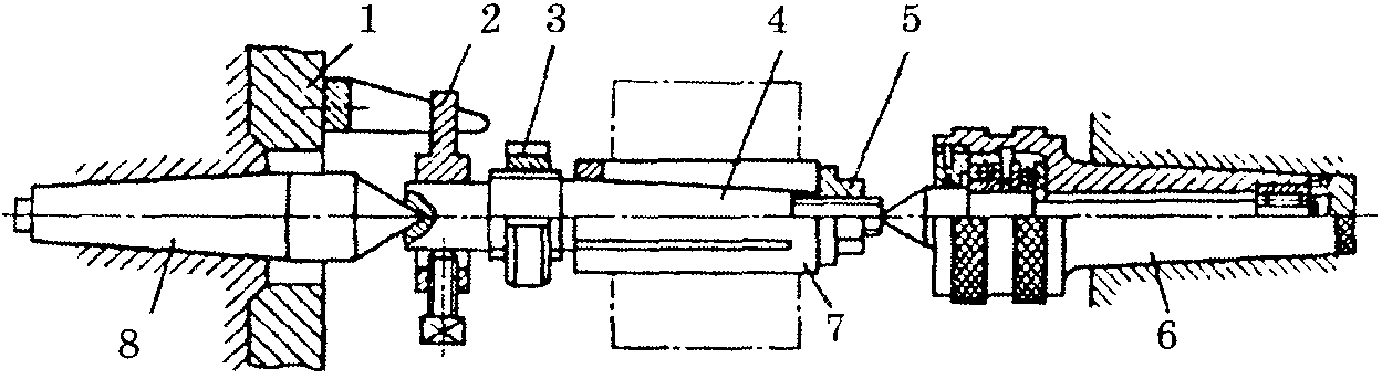
Fig.13. Processing in centers: 1 - driver chuck, 2 - collar, 3 - nut, 4 - rod, 5 - nut, 6 - live center, 7 - sleeve, 8 - front center
To transfer rotation from the spindle of the headstock to the workpiece, a driving chuck 1 is used (Fig. 13), set
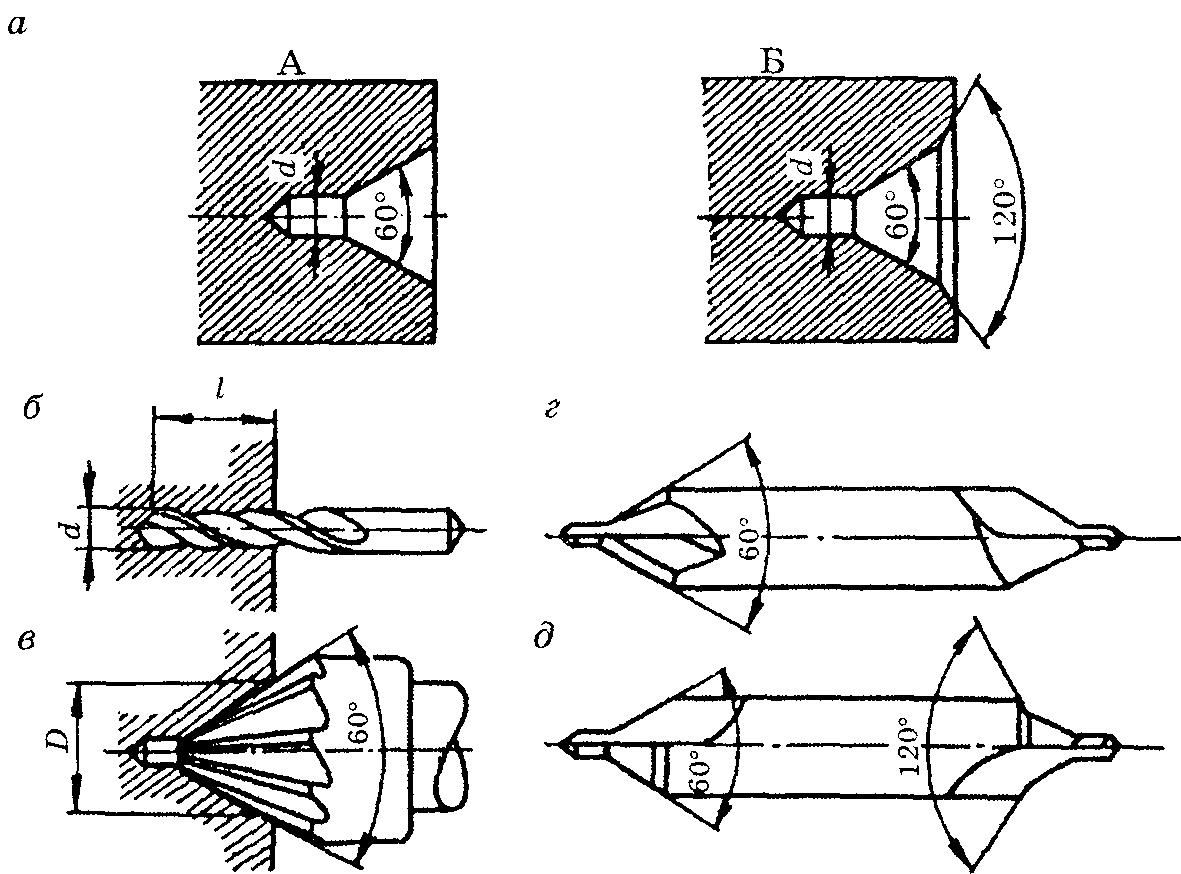
Fig.14. Center holes (a) and tool (b - cylindrical drill, c - countersink, d, d - drill combination)
cast on the spindle, and clamp 2, fixed on the workpiece.
The centers are installed in the machine spindle and tailstock quills. The center mounted in the spindle rotates with the workpiece. A simple center (Fig. 15, a) installed in the tailstock quill does not rotate, therefore it wears out itself and wears out the center hole of the workpiece. To prevent wear, a rotating center is used (see Fig. 7). Sometimes used: cut center when trimming the end; reverse center (Fig. 15, b) when turning workpieces of small diameter (up to 5 mm).
![]()
Fig.15. Turning centers: a - simple center (1 - cone, 2 - neck, 3 - cone, 4 - shank); b - reverse center
As well as other works that may interest you |
|||
| 58029. | Completion of the formation of world colonial empires. International Relations in the Last Third of the 19th Century | 122KB | |
| Objectives: To form an idea of India in the second half of the 19th century; to acquaint with the principles of British colonial policy in India; reveal the reasons for the course and results of the sepoy uprising; form their own judgments about the white man's burden ideology... | |||
| 58030. | India. Cultural - historical features. Economic and geographical characteristics | 118KB | |
| Purpose: to form students' general ideas about the culture and economic features of India; to improve the skills of students to independently select and analyze the material; continue the formation of skills to generalize and draw conclusions; cultivate responsibility... | |||
| 58031. | Old India | 78.5KB | |
| The word of the reader: Shanovnі uchnі shogodnі mi with you pomandruєmo on Skhid to tsіkavoї i enigmatic Іndії. Introduction of new material Geographical position of India Robot with a map. | |||
| 58032. | Zastosuvannya dієprikmetnik as a special form of dієslіv at the defense of projects "Particularities of surveillance behind the screen of pidlіtkіv" | 1.94MB | |
| META: turn into learning love before turning into Ukrainian language; I create an initiative and a vision of setting up to improve and protect your health; to develop the learning competence of learners and learners to communicate communicatively by means of language in different life situations... | |||
| 58033. | Simple and foldable tasks to include dimen- sions over units of area | 58.5KB | |
| Tsіlі: osvіtnі: form the number of smart and beginners, smarter solve problems, analyze mathematical problems; development: to develop logical and algorithmic ideas, knowledge and intellectual ability, to stimulate the development of learning to argue your opinion... | |||
| 58034. | Implementation of the integral to the modeling of processes | 2.54MB | |
| Initially: to study and systematize the knowledge of students with the topics “Integral and yoga study”; acquire consolidated knowledge about the geometric, physical and economic change of the integral; to form the mindfulness of the newcomers of the students independently to systematize and deepen the knowledge ... | |||
| 58035. | Application of the integral | 107KB | |
| Purpose: To generalize and systematize knowledge on the topic Application of the integral. Actualization of basic knowledge Definition of antiderivative; Definition of the indefinite integral; Definition of the integral... | |||
| 58036. | DESCRIPTION OF THE DESIGNATED INTEGRAL | 558.5KB | |
| To acquire consolidated knowledge about the geometrical and physical change of the integral. The teacher pronounces the end of the speech so that the formulating of the firmness will be true: Curvilinear trapezium is called Diya is wrapped up to differentiation First for one and the other functions are only revisited ... | |||
| 58037. | Arab conquest. Establishment of the Arab Caliphate | 248.5KB | |
| Consider the history of the creation of the Arab Caliphate and the emergence of Islam, get acquainted with the brightest achievements of Islamic culture; improve skills in working with a historical map | |||


How to cook ham in the oven at home
Pain in the lower abdomen during pregnancy, reasons for what to do Can the lower abdomen hurt if pregnant
Protein for muscle gain
The best vitamins for men according to customer reviews
How to lose weight on a vegan diet?