Job 1
Turning cutters
1. Parts and elements of the cutter
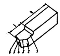
When cutting, cutting tools of various shapes and designs are used. The simplest form the cutting tool is a turning tool (Fig. 1). The cutter has a working part - head B, on which cutting elements are located, and holder A, designed to install and fix the cutter on the machine (in the tool holder).
Rice. one. Elements of cutting tools
Sharpening creates a wedge-shaped cutter head for better penetration into the material being processed. On the head of the cutter are its working elements (see Fig. 1): 1 - front surface 3 – main and 4 – auxiliary rear surfaces 2 – main and 6 – auxiliary cutting edges; 5 - the tip of the cutter.
2. Surfaces on the workpiece, coordinate
and cutting planes
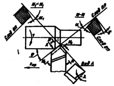
On the workpiece (workpiece), the following surfaces are distinguished (Fig. 2, a): 1 - processed, 2 – processed and 3 - cutting surface. To determine the angles of the cutter, the following coordinate planes are considered:
Main plane(OP) - a plane passing through the base of the cutter holder (Fig. 2, a).
cutting plane(PR) - passes through the main cutting blade of the cutter, tangent to the cutting surface of the workpiece.
Principal cutting plane (N – N) is a plane perpendicular to the projection of the main cutting blade onto the main plane (Fig. 2, b).
![]()
Rice. 2. Coordinate and cutting planes
Auxiliary cutting plane(N 1 – N 1) - a plane perpendicular to the projection of the auxiliary cutting blade onto the main plane. On fig. 2, b plane traces shown N – N and N 1 – N 1 .
3. Corners of the turning tool
The angles of the cutter determine the position in space of the elements of its working part. These angles are called incisor angles in static and shown in Fig. 3. The set of angles of the cutter makes it geometry.
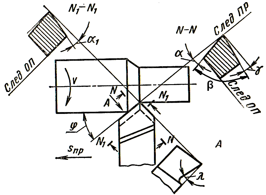
Rice. 3. Static cutter angles
Measured in the main cutting plane main rake angle γ, main relief angle α, taper angleβ and cutting angle δ(Fig. 3). Main rake angle- the angle enclosed between the front surface of the cutter and the plane perpendicular to the cutting plane, drawn through the main cutting edge. On fig. 3 is positive, but can be zero or negative.
Relief angle α- this is the angle enclosed between the main back surface of the cutter and the cutting plane.
taper angle β called the angle enclosed between the front and the main rear surfaces.
Angles γ, α and β are called main angles, as they define the geometry of the cutting wedge. The sum of these angles is 90˚, i.e. γ + α + β = 90˚.
The values of the angles γ and α are within: γ = –10…+15˚; α = 6–12˚.
The position of the auxiliary rear surface is determined by the auxiliary clearance angle α 1 (in the section N 1 – N 1).
Plan angles are measured in the base plane.
Leading angleφ – the angle between the projection of the main cutting edge onto the main plane and the feed direction.
Auxiliary lead angleφ 1 – the angle between the projection of the secondary cutting edge on the main plane and the feed direction.
Corner at the topε is the angle between the projections of the cutting edges on the main plane. The sum of the angles φ + φ 1 + ε = 180˚. For through cutters φ = 30–90˚; φ 1 = 10–45˚.
The position of the main cutting edge relative to the main plane is determined by the angle λ - angle of inclination of the main cutting edge. This is the angle enclosed between the main cutting edge and a line drawn through the top of the cutter parallel to the base of the plane. Angle λ measured in a plane passing through the main cutting edge perpendicular to the main plane.
a B C
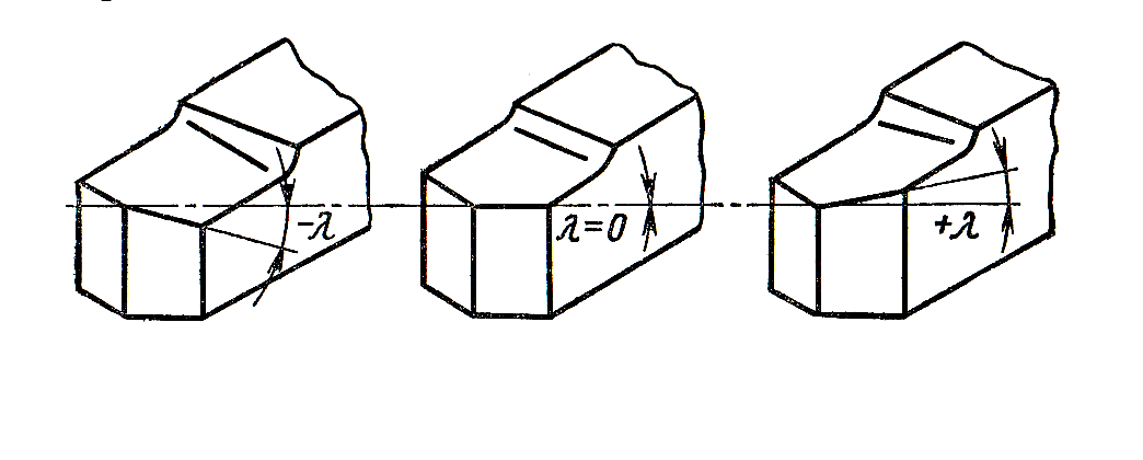 Rice. 4. Angles of inclination of the main cutting edge
The angle λ can be negative (Fig. 4, a) equal to 0 (Fig. 4, b) and positive (Fig. 4, v). For turning tools λ = -5…+15˚.
The angle λ affects the direction of chip flow and the strength of the cutting edge.
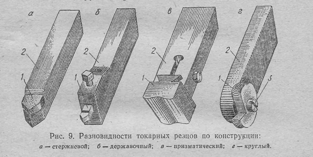
4. Classification of turning tools
Many types of processing are performed on lathes, which led to the creation of a large number of cutters for their intended purpose and design. The types of turning tools are mainly divided according to the following characteristics: type of processing, nature of processing, head shape, feed direction, manufacturing method and type of material of the cutting part.
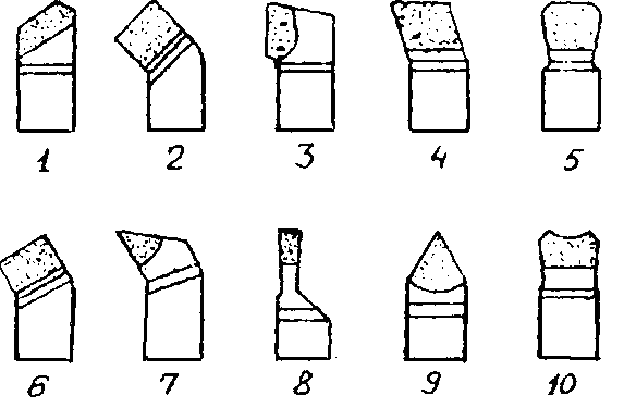
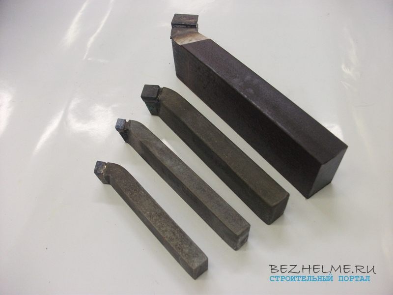
Rice. 5. Main types of turning tools
On fig. 5 shows the types of cutters by type of processing. Through cutters 1,2 and 3 are used for turning smooth cylindrical and conical surfaces. Scoring cutter 4 works with transverse feed when turning flat end surfaces. A wide through cutter 5 is used for fine longitudinal turning. The boring cutter 6 is used for boring through holes, and the boring stop cutter 7 is used for boring blind holes. The cutting cutter 8 is used for cutting the workpiece and for turning the annular grooves. For threading, a threaded cutter 9 is used, and for turning shaped surfaces, a cutter 10 is used.
According to the nature of the processing, the cutters are divided into roughing (roughing) 2, finishing 5 and for fine turning. According to the shape of the head: straight 1.3, bent 2, drawn 8 and curved.
According to the direction of supply, they are divided into right and left. The right ones work with the feed from right to left, and the left ones work from left to right. According to the manufacturing method, the cutters are whole, with a butt-welded head, with a soldered plate, with a mechanical fastening of the cutting plate. According to the material used, the cutters are made of high-speed steel, with plates made of hard alloy or mineral ceramics, with diamond crystals.
5. CUTTER ANGLE MEASUREMENT AND REPORTING
Angles γ, α, α 1 , φ, φ 1 , λ measured using a goniometer, and the angles β, δ and ε are determined by calculation using the formulas: β = 90 0 - (α + γ); δ \u003d α + β and ε \u003d 180 0 - (φ + φ 1).
The report should describe the main types of turning tools, provide a drawing of the turning through cutter designation of parts and elements of the cutter. Measure and calculate the angles of the through, scoring and cutting cutters and enter the data in Table. one.
Table 1.
|
Cutter name |
Cutter angles, deg. |
|||||||||
Make a drawing of a turning cutter with the necessary sections and put down all the angular designations.
CONTROL QUESTIONS
What movements are distinguished during cutting?
What is called the main movement and the feed movement?
Name the parts and elements of a turning tool.
What plane is called the main and what is the cutting plane?
What plane is called the main secant and what angles are measured in this plane?
Name the angles in the plan.
How to measure plan angles?
What angle is called the angle of inclination of the main cutting edge, and what does it affect?
Name the types of turning tools and their purpose.
10. How to determine the angles of sharpening of cutting and at the top?
Processing people metal parts with the help of cutters for a metal lathe, tool sellers know perfectly well what types they are divided into. Those who occasionally use turning tools for metal often experience difficulty in choosing suitable option. After reviewing the information below, you can easily choose the right metal cutting tool for your needs.
Design features
Each turning tool for metal consists of the following main parts:
- holder. Designed to be fixed on a turning device;
- working head. Used for processing parts.
The working head of the metal-cutting device contains various planes, edges. Their sharpening angle depends on the indicators of the steel from which the part is made, the type of processing. The tool holder for a metal lathe usually has a square or rectangular section.
Structurally, it is possible to distinguish the following types incisors:
- Direct. The holder and the head are either on the same axis or on two axes that lie in parallel.
- Curved. The holder has a curved shape.
- Bent. If you look at the top of such a tool, you will notice that its head is bent.
- Drawn. The head has a width smaller than the holder. The axes either coincide or are shifted relative to each other.
Varieties
The classification of turning tools is regulated by the rules of a certain standard. According to its requirements, these devices are divided into the following groups:
- Whole. Made entirely of alloy steel. There are fixtures that are made from tool steel, but they are rarely used.
- Devices, on the working element of which carbide inserts for turning tools are soldered. Most common at present.
- Turning cutters with replaceable inserts made of hard alloys. The plates are attached to the head with special screws, clamping devices. They are not used as often as other types of models.
Moreover, devices differ in the direction of delivery. They can be:
- Leftists. The feed goes to the right. If put on top of the instrument left hand, the cutting edge will be near the thumb, which is bent.
- Right. They are used most often, the feed goes to the left.
The types and purpose of turning tools form the following classification:
- carrying out finishing processing of the product;
- roughing (peeling);
- semi-finishing;
- execution of operations that require high precision.
From whatever category the metal-cutting tool is, it plates are made of hard alloy materials: VK8, T5K10, T15K6. Occasionally, T30K4 is used. Now there are many types of turning tools.
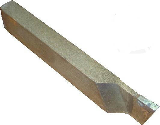
Straight through
Turning cutters have the same purpose as the bent version, but it is better to cut chamfers with a different device. Usually they carry out the processing of the outer surfaces of steel parts.
The dimensions, or rather, their holders, can be as follows:
- 25 × 16 mm - rectangle;
- 25×25 - square (these models are used for special operations).
Bent through
These types of turning tools, the working head of which can be bent to the left / right, are used for machining the ends of parts. In addition, by means of them it is possible to cut chamfers.
Holders have sizes:
- 16×10 - educational devices;
- 20×12 - non-standard size;
- 25x16 is the most commonly used size;
- 32×20;
- 40×25 - with a holder of this size, they are usually made to order, it is almost impossible to buy them in a store.
All requirements for turning mechanical cutters are prescribed in the state standard 18877-73.
Thrust bushings
These types of turning tools can have a straight or bent head, but this design feature is not taken into account in the marking. They are simply called stubborn walkers.
This device, with which the surface of cylindrical metal parts is processed on the machine, is the most popular type of cutting equipment. The design makes it possible to remove from the workpiece in 1 pass a large number of metal surplus. Processing is carried out along the axis of rotation of the part.
The holders of thrust turning cutters are available in the following sizes:
- 16×10;
- 20×12;
- 25×16;
- 32×20;
- 40×25
Bent scoring
It looks like a through passage, but has a different shape of the cutting plate (triangle). By means of such tools, parts are machined in a direction that is perpendicular to the axis of rotation. In addition to bent, there are persistent cutters, but they are rarely used.
Holder sizes are as follows:
- 16×10;
- 25×16;
- 32×20
Cut-off
The turning cutter is very common at the present time. According to its own name, it is used to cut parts at an angle of 90 degrees. Also, through it, grooves of different depths are made. It is quite easy to understand that you have a cutting tool in front of you. It has a thin leg with a hard-alloy plate soldered onto it.
Depending on the design, there are left- and right-hand cutting devices. It's easy to tell them apart. You need to turn the tool over with the cutting plate down and look at which side the leg is on.
Holder sizes are as follows:
- 16×10 - training equipment;
- 20×12;
- 20 × 16 - the most common;
- 40×25
Thread-cutting for external thread
The purpose of these devices is to cut threads on the outside of the part. Usually do metric thread, however, if you change the sharpening, it is possible to create a different type of thread.
The cutting plate, which is installed on this tool, has the shape of a spear. Materials of turning tools - hard alloys.
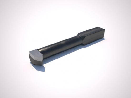
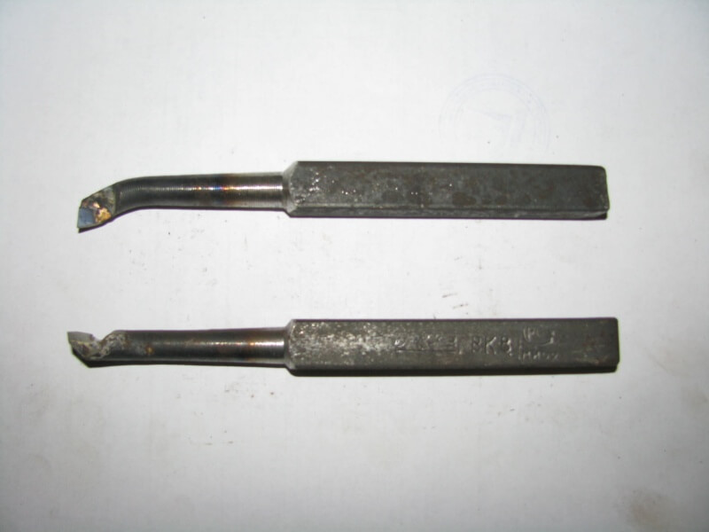
Thread-cutting for internal thread
With this tool, it is possible to make a thread only in a large hole. This is due to the design features. In appearance, it looks like a boring device for processing blind holes. However, these tools should not be confused. They differ significantly.
Holder dimensions:
- 16x16x150;
- 20x20x200;
- 25x25x300
The holder has a section in the form of a square. Sizes can be set by the first two numbers in the marking. 3rd number - the size of the holder. It determines the depth to which it is possible to thread the thread in the inner hole.
These instruments can only be used on devices equipped with a guitar (special accessory).
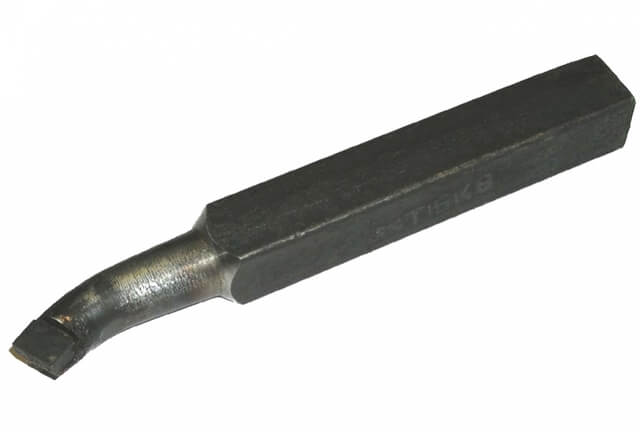
Boring for blind holes
The plate has the shape of a triangle. Purpose - processing blind holes. The working head is bent.
Sizes:
- 16x16x170;
- 20x20x200;
- 25x25x300
The largest hole radius that can be machined with a boring tool depends on the holder size.
Boring for through holes
Tools are designed for processing through holes that are created during drilling. The depth of the hole that can be created on the device depends on the size of the holder. The layer of material removed during the operation is approximately equal to the bend of the head.
Today in stores there are boring tools of these sizes:
- 16x16x170;
- 20x20x200;
- 25x25x300
prefabricated
When it comes to the main types of turning tools, it is necessary to mention prefabricated ones. They are considered universal, because they can be equipped with cutting plates for various purposes. For example, fixing cutting inserts on one holder different kind, it is possible to obtain tools for processing metal parts at a variety of angles on the device.
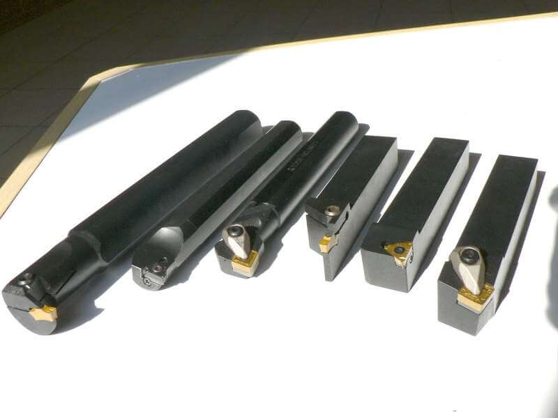
Typically, prefabricated cutters are used on devices with a numerical program management or special equipment. They are intended for turning contours, boring blind and through holes, and other turning operations.
Choosing a tool with which the processing of metal parts will be carried out on special device, special attention should be paid to the elements turning tool. The holder and working head are the most important parts of the cutting fixture. It depends on them how well the processing of the steel billet will be performed, what size holes can be made. If you choose the wrong working tool, you may encounter various complexities when processing a metal part. It is recommended to study the classification, to understand what this or that product is intended for. Based on the knowledge gained, you will be able to right choice metal cutting tool.
Download GOST
incisors can be divided into:
Pass-through 1-3 for turning external cylindrical and conical surfaces;
scoring 4 for turning flat end surfaces;
boring 5 for boring through and 6 for blind holes;
cutting 7 for cutting blanks;
threaded 8 for cutting external and internal threads;
blade 9 for finishing;
shaped round 10 and prismatic 11 for turning shaped surfaces,
slotted for turning circular grooves,
fillet for turning transitional surfaces along the radius, etc.
According to the nature of processing- roughing, semi-finishing, finishing and finishing blades.
According to the form of the working part- straight, bent, drawn and curved.
According to the manufacturing method- whole, with a welded or soldered plate; with interchangeable plates.
BY TYPE OF MATERIAL- from a quick cutter, with hard alloy plates, mineral-loceramics, with a diamond crystal. Cutters with multifaceted non-regrindable plates are widely used.
Feed direction- left and right.
Fitting size.
Turning straight through cutter: I- working part, II-rod. The stem may be square or rectangular shape The working part of the cutter performs the work of cutting.
1. Front surface- the surface on which the chips come off.
2. Back surfaces- facing the workpiece.
3. Main cutting edge formed by the intersection of the main back and front surfaces.
4. The top of the incisor - the place where the main and auxiliary cutting edges meet. The top can be sharp, rounded or in the form of a small straight line.
5. Auxiliary back surface facing the treated surface
6. Secondary cutting edge.
The cutting plane PR is a plane tangent to the cutting surface and passing through the main cutting edge of the cutter, the main plane OP is a plane parallel to the longitudinal and transverse feeds; main cutting plane NN ;Auxiliary cutting plane
Principal angles in the principal cutting plane.
The main angle α is the angle between the main flank and the cutting plane.
Taper angle β- front and main rear surface.
The rake angle γ is the front surface and the plane perpendicular to the cutting plane.
Cutting angle δ - angle between the front surface and the cutting plane; δ90-γ is negative.
Auxiliary corners measured in the auxiliary plane.
Secondary rear view α1- an auxiliary back surface and a plane passing through the auxiliary cutting edge perpendicular to the main one.
Auxiliary rake angle γ1- the angle is measured in the auxiliary plane.
Entering angle φ- projection of the main cutting edge onto the main plane and feed direction.
Auxiliary entering angle φ1- forms the surface roughness - by the projection of the auxiliary cutting edge on the main plane and the feed direction.
Angle of inclination of the main cutting edge λ- the main cutting edge and the plane drawn through the top of the cutter parallel to the main plane.
Angle at the vertex in the plan ε- projections of the main and auxiliary cutting edges onto the main plane.
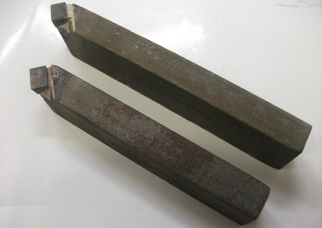
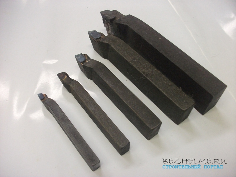
Very often, turning tools for metal are bought in our store, and if the suppliers who understand them correctly name each type of tool, then ordinary citizens often confuse the tools. In this article, I suggest that you familiarize yourself with the main types of turning tools - look at the photo, find out the size range and scope of each type.
All models are from the Kanash factory, their products are one of the highest quality on the market.
Important! All models of cutters are made with plates of different brands - most often these are VK8, T5K10 and T15K6. Other hard alloys are used quite rarely (for example, T30K4 and the like).
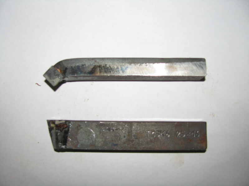
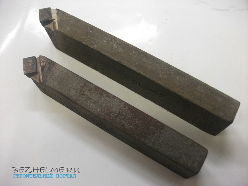
detachable
One of the most sought after incisors. Used for cutting workpieces. It cannot be confused with anything else - a thin leg with a soldered carbide plate. The scope is cutting at a right angle, they also cut thin grooves.
There are right and left handed. In the photo, you can clearly distinguish the right from the left - on the left, just the same left-sided. All others are standard right, in 90 percent of cases they are required for work. It is very easy to distinguish - take the cutter with the plate down (like a knife) and if the leg is on the right, then the cutter is right. Left means left (less common). Look at the photo, you can see everything there.
Dimensional range of holders:
- 16 * 10 mm - for small "school" machines
— 20*12 mm
- 25 * 16 mm - the most popular
- 40 * 25 mm - large incisors, rarely found on sale, only on order.
Straight bent
The name itself speaks of its scope - they process the ends of the workpieces, and also chamfer. The bent part, as it were, bends around the workpiece from the side. Photo:
The size range is also very decent:
- 16 * 10 mm - small for school machines
— 20*12 — custom size
- 25 * 16 mm - the most popular
— 32*20 mm
- 40 * 25 mm - rarely found on sale, only on order as a rule
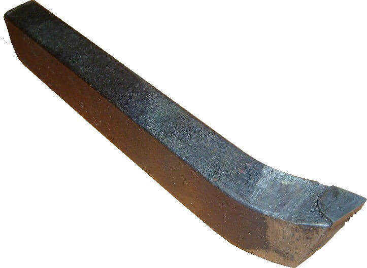
Through-thrust bent
The prefix "bent" is usually not used in everyday life, the incisors are simply called thrust through. But the bend can be seen, there are without it.
Scope - one of the most needed incisors. Used for processing cylindrical workpieces. The bend just allows you to grind round parts, removing as much metal as possible in one cut of the cutter. The processing of the part goes along its rotation!
The size range is also wide:
— 16*10 mm
— 20*12
— 25*16
— 32*20
— 40*25
There are also left and right. In the vast majority of cases, the right models are used.
straight through
The scope is the same as that of the bent through passage, however, it is more convenient to chamfer. And direct most often process metal surfaces. Rarely used in production.
Size range:
- 25 by 16 mm - standard with square holder
- 25 by 25 mm - non-standard holder, for some special work
Scoring bent
Most often it is confused with a persistent through passage. The undercut has a triangular plate, pay attention! Photo:
Scope: workpieces are processed across the axis of rotation (perpendicular). In addition to bent models, there may also be persistent ones (but they are not in demand as a rule).
— 16*10 mm
- 25 by 16 mm
- 32 by 20 mm
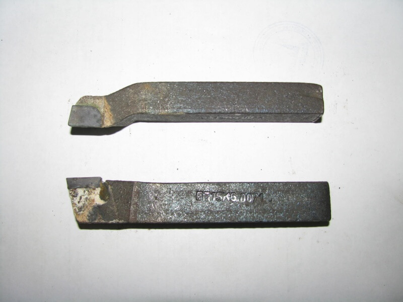
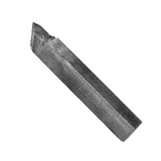
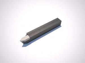
for cutting external thread
Scope: the name speaks for itself - they cut threads with such cutters. What? If you take a cutter from the factory, then, as a rule, it is “sharpened” for metric threads. For other types of threads, it will need to be reground.
The plate is installed “spear-shaped” (its correct name is cut-off, sold separately), it can be of a different alloy (brands are indicated at the beginning of the article). The resulting thread on the workpiece is external (the so-called "dad") - a bolt, stud, etc.
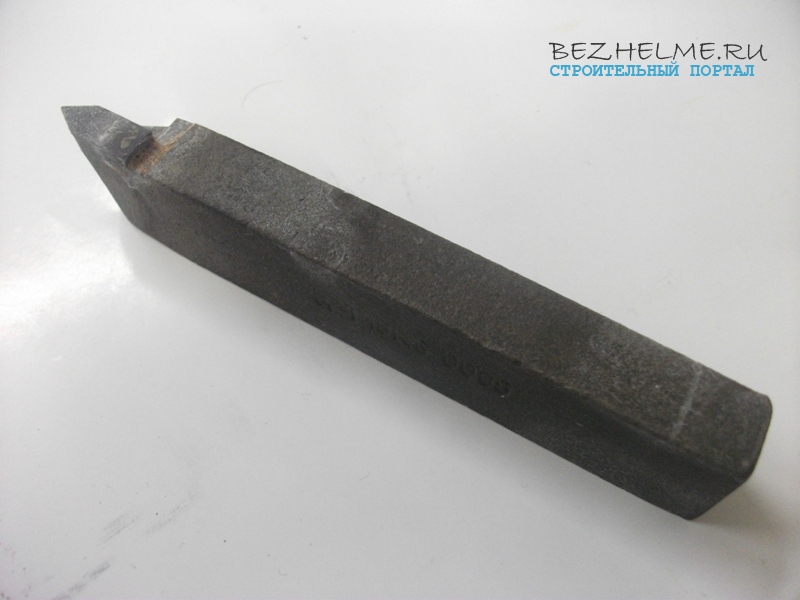
Most requested sizes:
16*10mm
25*16mm
32 * 20 mm - not used so often
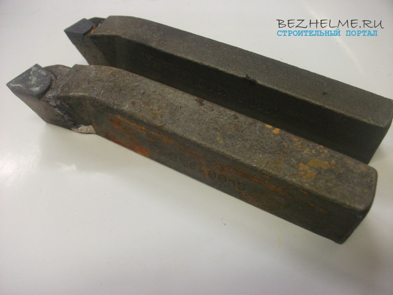
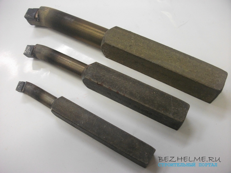
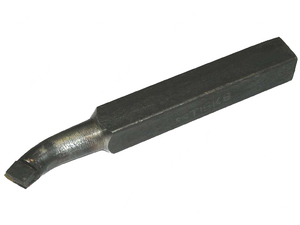
for cutting internal thread
If the outer thread can also be cut, then only the thread is cut with the inner one. large diameter. This can be understood by the size of the incisors themselves. Photo:
Important! Do not confuse this tool with boring tools for blind holes, they are similar in appearance, but fundamentally different! Boring below in the article, compare.
— 16*16*150
— 20*20*200
— 25*25*300 mm
The first and second digits are the size of the holder (it is square in cross section), and the third digit is the length of the holder. The longer - the deeper you can cut the thread inside the workpiece.
Please note that in order to use such a cutter, it is necessary that your machine be equipped with a fixture called "guitar".
Boring for blind holes
Scope - for boring blind holes. They work as if from the end, for which a sort of “bend” of the head is needed. Whereas the “internal” (see below) completely enters the workpiece with the holder.
- The plate of this cutter is triangular, the same as that of the scoring cutter (see above).
Photo: 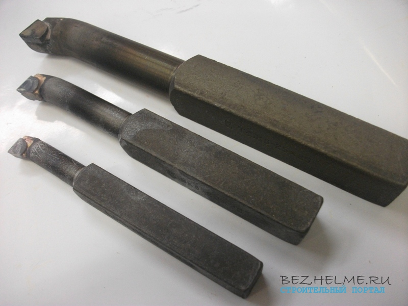
— 16*16*170 mm
— 20*20*200 mm
— 25*25*300 mm
The larger the cutter, the larger diameter holes can be bored!
Boring for through holes
Scope - they bore parts "inside" along the entire length. The longer the holder, the more inside you can bore. Most often, the part is bored after drilling it with a large drill, it is also possible to work according to existing dimensions.
The plate is straight, there is no protrusion, which means that the cutter easily enters the “tube” resulting from drilling and bores it from the inside, passing through. The layer of chip being removed is approximately equal to the curvature of the cutter head
— 16*16*170 mm
— 20*20*200 mm
— 25*25*300 mm
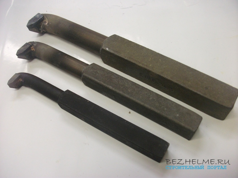
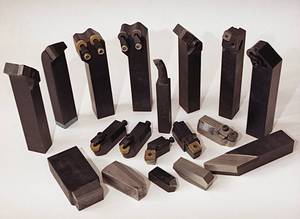
prefabricated
One of the rarest incisors. They are also called universal, because they are equipped with different plates, thanks to which it is possible to process workpieces of various shapes at different angles. They differ from each other both in the size of the holder and in the shape of the insert that can be clamped.
The photo below shows 3 different models:
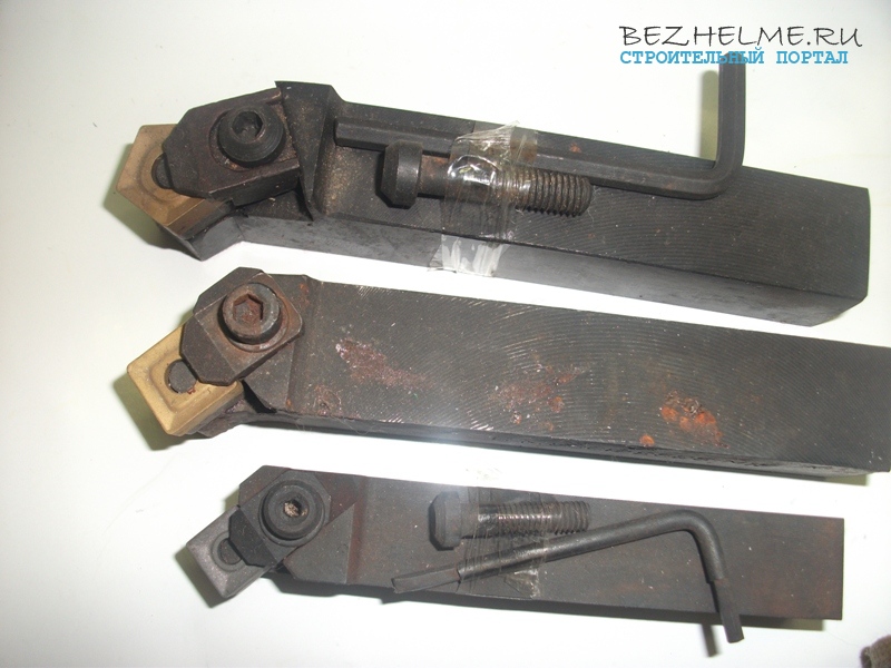
The smallest cutter has a 20 x 20 mm holder and is equipped with a 4-sided square insert.
A little more has a holder already 25 mm and the insert is also square, but larger in size.
Well, the third cutter is similar in parameters to the second one, it has a 5-sided plate by default, but you can get it and put it the same as on the second one - a large square one.
In terms of money, these cost around 300 rubles apiece, but it’s difficult to find them on sale, it’s sometimes problematic to even bring them to order.
The lathe is a brilliant invention of mankind. Now it is difficult, and even impossible, to do without it in almost any industry. Take, for example, the automotive industry. In one engine alone, how many round parts that must first be processed on lathe, and then put in its place in the "heart" of the car. And his wheels are round, and the cast disks need to be given a perfectly round shape.
Equipment for making or processing something without special devices It's a useless pile of metal. The lathe is no exception. To work on it, you need tools and, first of all, incisors.
Cutter design
![]() The cutter consists of a rod (holder) and a head.
The cutter consists of a rod (holder) and a head.
The holder is mounted in the tool holder of the lathe. It has a square or rectangular shape. The head is working part of the cutter with edges and planes, which are sharpened at certain angles, which is necessary for processing metal blanks in various ways.
Heads are divided into:
- whole;
- with soldered or welded plates;
- with mechanical fastening of the plate.
One-piece head is one piece with the holder (rod). Such cutters are made from a special steel called tool steel with a high carbon content, or from high speed steel. However, such a turning tool is used extremely rarely.
Most often, cutters with soldered or welded plates are used to process metal blanks on lathes. They made of hard alloy or high speed steel, which include metals: tungsten, titanium, tantalum and others, characterized by high strength and price, of course. Such a machining turning tool is used, depending on its brand, for machining parts made of cast iron, non-ferrous metals, non-metallic materials, as well as workpieces made of any steel.
Carbide inserts are very brittle and must be handled with care when handling complying with all technological requirements.
Are applied in turning of a head with mechanical fastening of a plate. Unlike soldered or welded, it is fixed in the head mechanically. It is convenient if the basis of the material from which the plate is made is mineral ceramics.
Thus, the materials of the working part of any turning tool are:
- high quality carbon steel;
- high speed steel;
- hard alloys.
Types of turning tools
They are of the following types:
- cutting;
- walk-throughs;
- undercut;
- threaded;
- boring;
- universal.
Cut-off
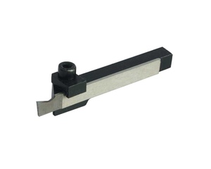 Any turner cannot do without a cutting tool. It is designed to cut the workpiece right size from metal blanks, rods, pipes, hexagons, etc., the length of which is greater than the required parameters of the future part. His difficult to confuse with others, since it has a thin leg, at the end of which a hard alloy plate is soldered. The narrower it is, the smaller the cut and, accordingly, less waste in the form of chips. The cut is made at a right angle. The cut-off cutter can cut thin grooves.
Checkpoints
 Passing cutters are divided into:
- bent;
- persistent bent;
- straight.
The bent through passage is designed for processing the ends of the workpiece, as well as chamfering. He got this name because during the processing of the part, the cutter, as it were, goes around it from the side.
Another type of through cutter for a lathe is a persistent bent one. It is one of the most necessary when turning a part from a cylindrical billet. Its bend allows you to remove a lot of excess metal in one pass when turning a round part. The cutter during processing moves along the rotation of the part. Passage bent are right-handed and left-handed. Most often in practice, right-handed ones are used.
The straight through passage is used in the same cases as the bent thrust through passage. Them most often the surface of the metal is processed, however, turners rarely use it in their work.
Scoring
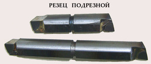 The next type of turning tool is a bent scoring tool. It should not be confused with a through-thrust. In the undercut, in contrast to the through thrust, the working part is, of course, also a plate made of hard alloys, but of a triangular shape, one of the sides of which is rounded, while in the through passage it is rectangular. undercut bent workpieces are processed across the axis of its rotation, holding the tool perpendicular. There are also scoring thrust cutters, but they are not in demand.
Threaded
 A tool kit for a lathe will be incomplete if there are no threaded cutters. They are of two types:
- for cutting external threads;
- for cutting internal threads.
First type designed for cutting external threads on workpieces such as bolts, studs, etc. The cutter plate resembles the shape of a spearhead. The cut thread can be of two types: metric or inch, depending on the design of the cutter.
The second type is used for cutting internal threads in the workpiece. Such a cutter has a different appearance, although the shape of the cutting insert remains the same as that of an external threading tool.
Boring
They are of two types:
- for boring blind holes;
- for boring through holes.
 In the first case, the cutter is used when there is no hole in the workpiece. The hole, of course, can be drilled in advance alternately with drills of different diameters, but on a lathe this operation will be easier and faster. For this, a boring cutter is used, in which the plate is triangular, like the undercut one, but, unlike it, the boring head has a bend. It is needed in order to be able to bring it from the end of the workpiece and start boring it from the center, going inward, making a hole desired diameter. You can bore holes of any diameter, but this requires large cutters.
For boring through holes on a lathe, a different type of cutter is used. A hole is pre-drilled in the workpiece with a large-diameter drill, and then it is bored to the desired size. However, at the same time government plays an important role the longer it is, the more you can bore the hole in the workpiece. The straight plate, which does not have a protrusion, allows the tool to easily go inside the tube drilled in advance in the workpiece and bore it, passing through.
Universal cutters are also called prefabricated, because different inserts can be mounted on one holder and, thus, workpieces can be machined. various forms at different angles. Tool holders are different sizes. This kind turning tool Rarely used, and therefore produced in small quantities. If it is found on sale, then the price is quite high, unlike other types.
Tool cost
 The price of each turning tool for metal depends on what material it is made of, the type of tool, that is, what it is intended for when processing metal parts and other factors.
For example, the design of a cut-off cutter is simpler than for threading, respectively, and its price will be lower. However, if the composition of the material from which the head is made includes expensive metal, then the price of the tool will be much higher.
You should not buy a machining tool for metal lathes cheaper. It has long been proven that the miser pays twice. It is better to buy a tool at a higher price, but a quality one that will last longer and not be disposable.


Mixed Personality Disorder: Causes, Symptoms, Types and Treatments
GTA 4 control settings
FAQ on Smuggling in GTA Online
LSPDFR - welcome to the police
The huge map of Grand Theft Auto San Andreas and its secrets