Our article is devoted to nostalgia for school workshops of labor training. Many people know how to carry out turning work on wood, but not everyone can afford to buy and maintain equipment for this. Is it possible to assemble a machine with your own hands that meets the technology and safety requirements - let's figure it out together.
What does GOST say
The good news is that you don't have to reinvent the wheel. The entire assembly process and drawings of each machine module are described in TU3872-477-02077099-2002, and although this document is not publicly available, it can be obtained upon individual request. Although this is unlikely to be needed: the device of the machine is so primitive that you can easily navigate the intricacies of its manufacture even from images from school textbooks.

Another positive fact - STD-120M, apparently, was designed with the expectation of manufacturing "on site", so you can either find almost all the components for assembly on sale, or make and modify it yourself. Naturally, if it becomes possible to inexpensively purchase components for this machine or its younger brother TD-120, do so. Factory-made parts are more reliable, easier to align, and the unified frame design allows you to assemble one machine from many donors.

Please also note that the standardization of modules largely determines the safety of equipment operation. The basic principles of industrial safety are announced in GOST 12.2.026.0-93, and the electrical protection rules are set out in GOST R IEC 60204-1. Conform to these standards any part or machine module that you manufacture.
Bed manufacturing
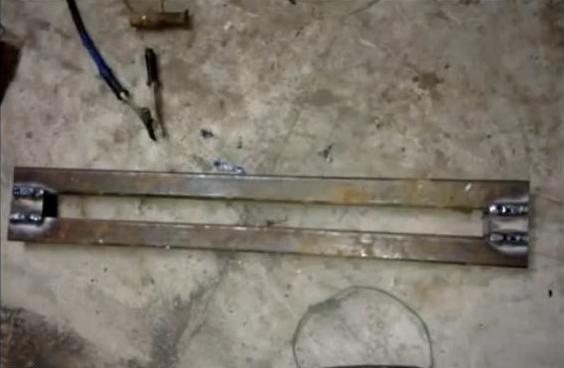
Instead of a cast iron bed, we offer a lighter welded construction. It consists of two segments of the 72nd corner steel 1250 mm long. The temptation is great to make the bed larger for processing more massive products, but remember that such changes require intervention in other parts of the machine. Perhaps you should take TT-10460 as a sample for a meter-long blank.
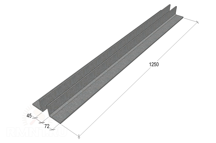
We place the corners on a flat horizontal plane with shelves to each other. We insert calibrated inserts between them so that the guide beds are located strictly parallel with a distance of 45 mm. To fasten the guides, we use two corners, the same as on the bed, 190 mm each, which we put from the front and rear edges. Before welding parts, it is recommended to squeeze them with clamps so that the metal does not lead when it cools.
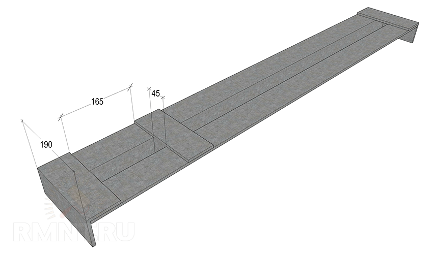
The guides are fastened with another 190 mm jumper, in the lower shelf of which there are cutouts for each corner. This part is installed with the formation of a cell, the dimensions exactly corresponding to the landing spike of the headstock, in the standard version it is 45x165 mm.
Such a bed can be attached in any way to a workbench or deck, but it is recommended to weld all fastening elements without violating the integrity of the base. If a separate corner is allocated for the machine, weld the legs from the pipe perpendicular to the corners of the frame and, for greater stability, make them a small “bracing” with a sledgehammer. Ultimately, the weight of the bed, fastened to the workbench, should not be less than 60-70 kg.

handcuff
This element conditionally consists of two parts. For both, one type of workpiece is needed - a 50 mm corner, inside of which another, 30 mm wide, is embedded. They are welded along the edges, as a result, two segments of 260 and 600 mm should be obtained.
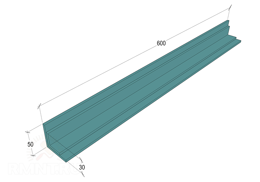
A short detail is an adjustable handrest base. One of the shelves is cut off, but not completely, a segment of 110 mm long with an oblique cut is left. The other shelf is cut at a right angle of 60 mm from the rear edge. From a thick steel plate, you need to make a reciprocal frame that will clamp the guide of the handstand rack.

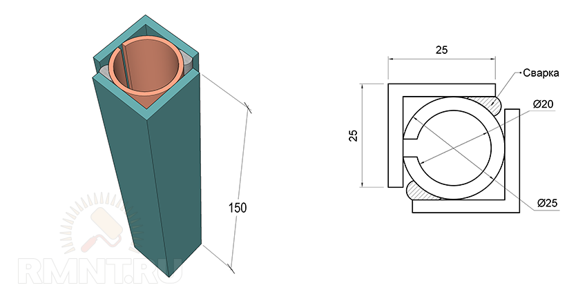
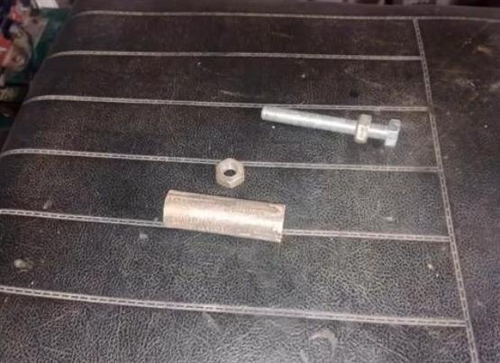
To make a guide with a clamp, take an ordinary pipe per inch and make a longitudinal cut in it with a grinder. The resulting sleeve should be about 150 mm long, we put it in a 25 mm corner, orienting the slot outward perpendicular to one of the shelves. We tighten the parts with a clamp and boil along the entire length closest to the slot of the shelf. We cover the workpiece with a second corner of the same length and attach it to the tube with reverse side.
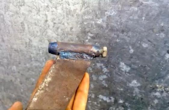
The guide is welded flat to the protruding shelf of the adjusting rail from its inner side. For fixing, a screw with a long handle and a nut welded to the rail are used. On the reverse side, the reciprocal plate is fastened with a cotter pin or even a welded bar.
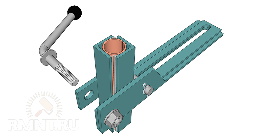
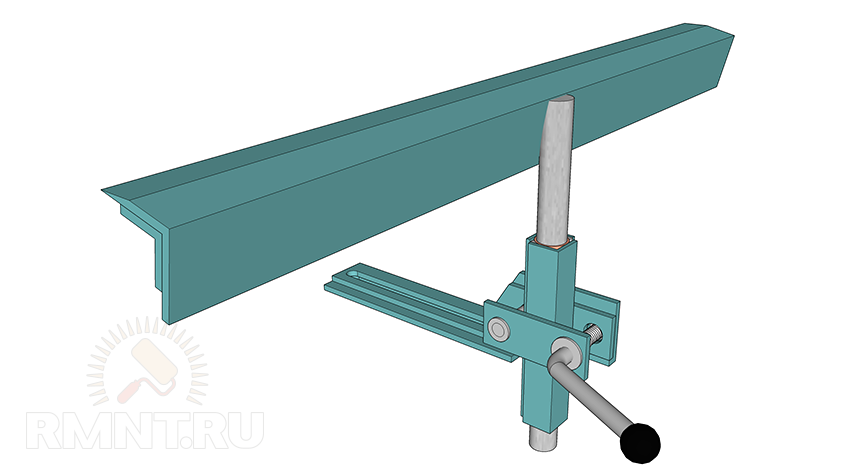
The handpiece is mounted on a 20 mm smooth reinforcement rod, which is located in the center on the outside of the corner blank. The rod fits snugly into the tube of the guide system, and when the screw is tightened, it is reliably compressed from all sides. A long corner blank 600 mm long is welded to the bar with a slight inclination towards itself and a slightly “sharpened” leading edge.

Drive and transmission
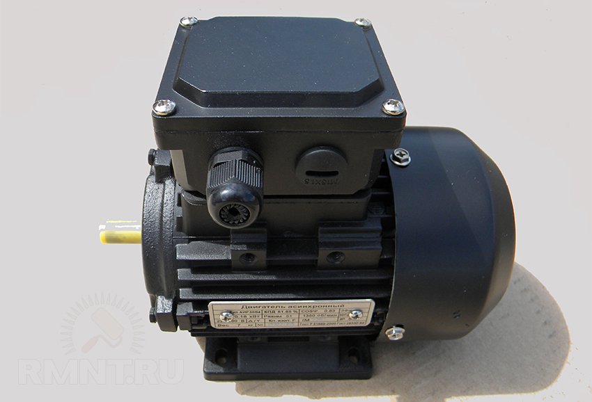
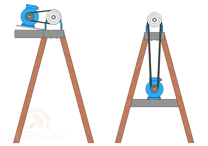
The standard drive option is an asynchronous three-phase motor with a power of up to 2 kW (usually 1.2 kW), connected to the headstock shaft by a V-belt transmission on two-grooved pulleys. The bed for fastening the engine can be located between the legs of the frame, or on an additional platform behind the headstock, which will complicate the assembly, but make it more convenient to transfer the belt.
It is far from always possible to use the engine with the desired shaft speed, so reaching the final speed is carried out by adjusting the diameter of the pulleys. For example, if you have a blood pressure at 1480 rpm, then in order to reach the coveted 1100 and 2150 rpm, the diameters of the leading and driven streams must be related as 1:1.5 and 1.3:1.
When placing the engine, it is useful to provide the frame with a plate fixed on the gate canopies. An engine installed according to such a system will always be in a suspended state and will ensure that the belt is tightly pressed by its own weight. And if you equip the platform with a pedal, the speed can be changed even on the go.
On the electrical side, there are no difficulties either. Switching is performed by a standard three-phase starting button with reverse, for such a low-power motor there is no need to install a starter. The only moment is the inclusion of DC braking while holding the stop button, for which you need a powerful diode bridge (on KD203D) according to a typical switching circuit.
The frequency controlled motor can be used as a direct drive, eliminating the need to design a headstock. To do this, you need to fix the engine on the transition platform, in the lower part of which there is a longitudinal mounting spike 45 mm wide as a regular alignment tool for the STD120 frame.

Headstock
Looking ahead, we note that both the headstock and tailstock include parts that can be made only with access to a metal lathe. Otherwise, it makes sense to think about purchasing ready-made modules, or at least their cast consoles.
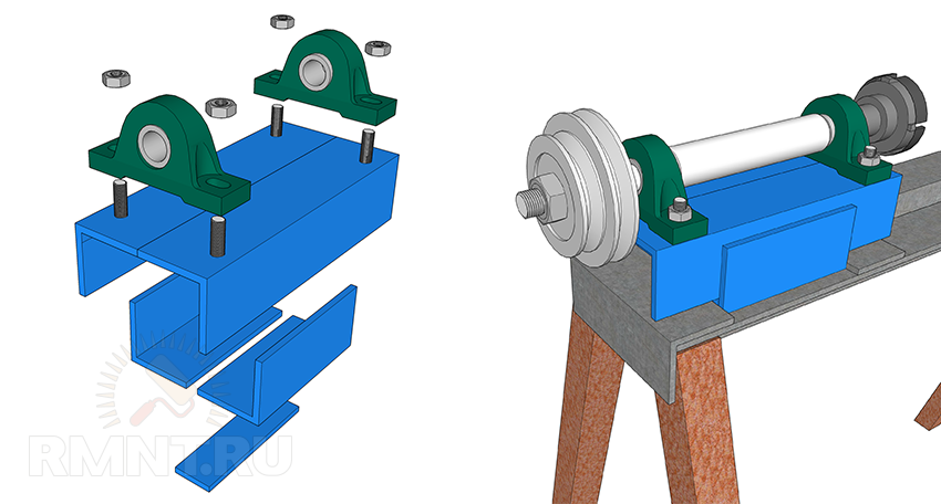
At the base of the headstock are two S, V or U type bearing housings permanently mounted on an angle steel frame. Unfortunately, it is impossible to predict which sizes will be available, however, in overall result the height of the spindle axis above the frame must be at least 120 mm. Given that the diameter of the spindle shaft is about 25 mm, the bearing assembly will be of most interest with a total height dimension of about 70 mm.

The shaft is machined from round timber carbon steel with a diameter of 40 mm with a tolerance of not more than 0.05 mm. There are two main variations of the shaft. The first is the simplest: the shaft pillar remains in the center, then descents are made to the bore diameter of the bearing units, then threads are cut at the ends. For axial fixation, four grooves are machined on the shaft for retaining rings.
 1 — seats for bearings; 2 - grooves for retaining rings
The second variation has an extension in the form of a skirt just behind the thread of the cartridge. It is designed to install a flanged thrust bearing mounted on the ledge of the headstock base. This approach reduces bearing wear if the machine is processing massive parts.
The base of the headstock is two pairs of corners or two channels turned towards each other. By bringing the vertical flanges together and apart, you can adjust the height of the base to the axial height of the existing bearing units. From below, a 45 mm strip is welded to the base, which acts as an adjustment groove. The assembly order is important: first, bearings are pressed onto the spindle, then the shaft is mounted on a frame with a substrate of adjusting steel plates.
tailstock
Making a tailstock is not an example easier. It consists of four parts:
- Angle steel base 100 mm high, following the same principle as for the headstock. Two 50 mm corners are bolted on top across the top, in their shelves in the center there are cutouts of 40 mm wide squares.
- The guide (external) is a thick-walled square tube 40 mm wide, 150 mm long and with an internal clearance of 20x20 mm. In the back, you need to install a plug with a thickness of 6-8 mm and with a hole in the center of 8 mm, it is fastened with two screws through the walls of the tube.
- The inner tube, also known as the quill, is made from a 20 mm profile tube, preferably thick-walled and milled exactly under the guide clearance. An M14 nut is welded in the back of the quill, a metal rod is inserted and welded into the front, widened up to 5 mm to fit a double-row bearing.
- The drive screw has a thread for a nut in the quill (it is desirable to make it trapezoidal), in the rear part there is a transition to an 8 mm thread for fastening the flywheel.
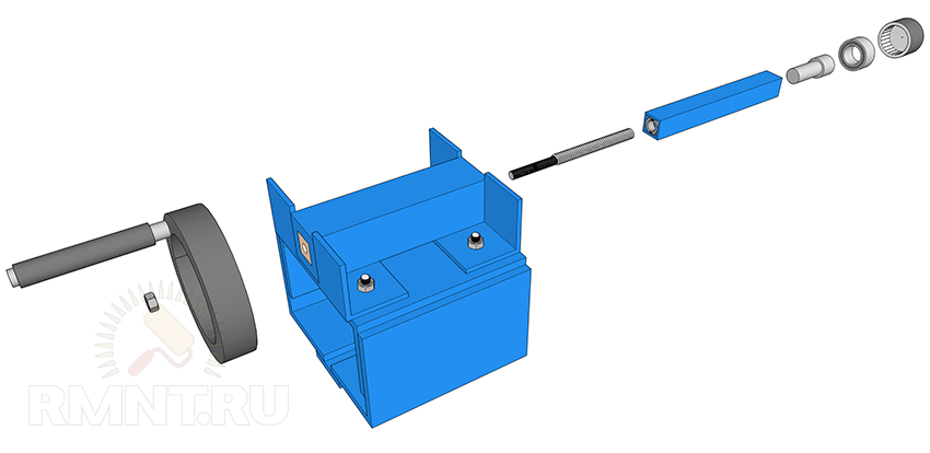
The principle of operation and the assembly scheme of the quill are quite obvious, but special attention should be paid to the alignment of the axes. The guide tube, fixed by welding in the cutouts of the corners, can be raised higher or lower due to the linings made of transformer steel. The headstock and tailstock must be absolutely aligned, the tolerance is only a couple of tenths.
As for the method of attachment to the frame, it is the same for headstocks and for the handpiece. The M14 or M16 studs are welded to the bottom of the stocks, and a large plowshare bolt is inserted into the slot of the armrest. From below, the modules are tightened with nuts with rods welded to them like levers. For uniform tight pressing from below, a 50 mm channel is placed as a striker.
Properly assembled do-it-yourself metal lathes will enable those men who prefer to do everything on their own to perform many useful operations.
With this mini device, you can different kinds processing of metal blanks, starting from the knurling of the relief on the surface and ending with cutting, if necessary, threading.
The desktop metal lathe opens up new possibilities for the home master and allows him to turn work into pleasure.
Meanwhile, not everyone can afford to buy a ready-made device in a specialized store.
In this case, the way out of their situation can be the assembly of such a mini machine with their own hands, and everyone can do this, if they have the desire, the appropriate material and tools.
Homemade turning device great for the garage and home and will be able to perform a large amount of related work, such as sharpening cutters, threading, grinding the surface of any metal fixture and much more.
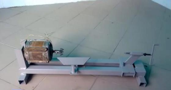
A home-made metal lathe, which can be seen in the photo below, assembled in accordance with all the rules, will not be inferior to professional equipment in any way.
The turning unit is capable of performing a huge number of the most useful functions, without which it is difficult to imagine any metalworking.
Modern devices of this type are able to work with almost any material, from metal and wood to plastic.
Such a unit makes it possible to perform many operations. First of all, with the help of it, you can get a finished part of a given size and shape from a workpiece.
In addition, with its help, a tool is bored, a part is processed, technological holes are drilled, threads are cut, and a corrugated surface is rolled.
Currently, a huge selection of this type of equipment can be found on the relevant market, however, in most cases, all of it is not intended for the garage and homework but for professional use in enterprises.
As home appliance it is best to assemble such a mini device with your own hands, which can work with both metal and wood.
Of course, self-assembly will require certain skills, appropriate equipment and tools, as well as some other devices.
It is best if a do-it-yourself mini-turning unit will allow you to process small wooden blanks, for example, if necessary, repair furniture, as well as work with metal.
With the help of this device, you can eventually learn how to independently produce various kitchen utensils and interesting pieces of furniture with elegant decor elements.
The turning unit allows you to quickly create parts of a very different section, as well as to carve all kinds of fixtures.
The principle of operation of any turning equipment is that the workpiece is given a rotational movement, after which it is processed to the required shape. different type incisors.
Meanwhile, a desktop metal lathe, assembled at home, is a rather complex unit, which consists of many different devices and elements.
History of creation
The first devices, which, according to the principle of their work, resembled modern turning units, were born several thousand years ago.
Such devices were used mainly for working stone and wood. A little later, they began to be used to work with metal blanks.
The turning device in its modern sense appeared at the beginning of the eighteenth century.
Its inventor was the engineer Nartov, who used parts in his unit that were made of metal.
Meanwhile, the first turning devices were driven by manual force using a special flywheel.
Over time, the drive was transformed into an automatic one, and the necessary rotational movement was created by means of a transmission shaft and transmitted through belt drives.
With the advent of electric motors, it was the electric motor that became the main drive of the lathe, which is used in this type of equipment in our time.
As before, a modern turning unit consists of a set of certain mechanisms and elements that interact in a special way with each other.
His equipment includes a variety of elements.
So, the number of revolutions of the spindle used to be regulated through the use of a step-pulley drive, and today this operation is carried out using a gearbox.
Modernization over time has affected absolutely all the nodes of the lathe, however, the scheme and principle of its operation have remained the same today as they were many years ago.
Almost all types of workpiece processing are carried out using metal cutters made of high-quality steel.
Modern equipment of a lathe allows many operations to be performed more efficiently and quickly, which means that the functionality of such equipment has increased several times.
Lathe device
A mini lathe, which can be used to process simple wood and metal workpieces, must necessarily consist of a frame, headstock and tailstock, as well as stops for cutters and, of course, an electric drive.
The main purpose of the frame in this case is to create a support for all elements of the device.
In turn, the headstock must be rigidly fixed and serve as the main base for the device of the rotational assembly.,

The transmission mechanism in such a unit, as a rule, is located in the front of the frame and provides a reliable connection between the leading center and the main drive, which is an electric motor.
In order to firmly fix the workpiece, a tailstock is installed, which can move along the guide, depending on the size of the workpiece.
For a lathe with low power, you can use a motor from a drill as an electric drive.
Such a mini machine will make it possible to perform simple operations with small workpieces, however, if you plan to work with massive material, it is better to use a more powerful motor.
It is better to equip a device for transmitting the required torque directly to the workpiece with a belt drive, however, a direct connection can also be made, for which the leading center should be firmly mounted on the motor shaft itself.
In any lathe, the driven and leading centers must necessarily be placed on only one axis, otherwise strong vibration will be observed during operation.
The frame of a homemade lathe should be assembled only from metal profiles and corners, using a correctly drawn up drawing.
More details about the device of a homemade lathe are described in the video below.
Lathe assembly process
A self-assembled machine will allow you to perform quite complex operations at home, in addition, it can be used to sharpen various workpieces if necessary.
The easiest way is to assemble a beam-type machine with your own hands, the scheme of which is not too complicated. To assemble it, you will need not only the appropriate material, but also a tool, as well as a drawing.
Having prepared the tool and material for work, you should make racks from wood and screw bolts to them.
Racks must be rigid and not loosen during operation of the unit.
To strengthen wooden racks, as well as incisors, it is recommended to use a handguard, which can be made from two boards. The tool holder must be able to rotate freely.
When making all the elements of the machine with your own hands, only professional tools should be used.
The video below tells you what tool is needed for the job and how to independently assemble a lathe, with which you can perform both sharpening workpieces and many other operations.
In order to fix the workpiece to be processed, nuts are used, which should not only firmly strengthen it, but also make it possible to move in a given direction under the cutters.
You should also think carefully about the device of the electric motor, with which it will be produced necessary sharpening blanks.
For these purposes, you can use a small engine with low power. It will allow you to perform simple processing of a variety of workpieces.
Also, using the appropriate tool, this unit can be additionally equipped with a nozzle for grinding wheels, which will further expand its capabilities.
Learn more about how to have the whole essential tool and material, assemble the machine with your own hands, is described in the video below.
Cylindrical wood products are common in all areas of life. These can be tool handles, balusters under railings, furniture parts, door handles. In construction markets and hardware stores, you can pick up any workpiece, which, as a rule, is made on a wood lathe.
If you buy a set for stairs to the second floor of your private house, the amount can become unbearable even for the owner of suburban real estate.
Everyone knows that wood is the easiest material to process. With an axe, a hacksaw, and sandpaper, you can do anything. Except for round parts.
It is these practical decorations made of wood that sell the most expensive. To produce them in the slightest degree in large numbers- you need a desktop lathe. And again the question of cost arises (ready-made machines in the assortment are presented in stores). 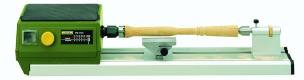
Looking at the photo, anyone home master think about it, what's so difficult about the design? And he will be absolutely right. A woodworking machine can and should be done with your own hands.
Its design is quite simple. The workpiece is fixed along the axis of rotation. Torque is applied to one of the stops. The product rotates and can be machined with any cutting or grinding tool.
An example of a simple wood lathe design that you can assemble with your own hands in a couple of days - video
Short workpieces of small diameter, in general, can be clamped with one end in the chuck of a hand drill (having previously fixed it), and turned to the desired shape.
Speaking of a drill - with its help it is easy to make a low-power lathe.
Even in the old magazines "Modelist Constructor" the simplest devices for wood processing were offered. 
We make a lathe for wood with our own hands
The design is primitive, but absolutely workable. And most importantly - the sketch gives an idea of how exactly the machine should look like.
Components:
It is a horizontal frame structure on which all other parts of the unit are located. 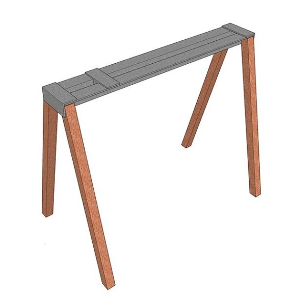
Important! Lathe must be complete. Therefore, it is impossible to fasten the component parts separately. During operation, the machine vibrates (due to the asymmetry of the workpiece). All parts must work in sync, otherwise the part may enter into resonance and break out of the fastener.
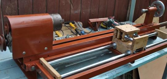
Homemade wood lathe with a reliable bed. Detailed guide how to do it yourself.
The frame can be installed on a workbench (desktop version), or have its own supports (legs). An important element the bed is a longitudinal guide, a rail (or other device) for moving individual elements (tailstock along, a handpiece across the axis of rotation).
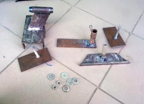
Lathe handpiece
It is a support for the cutting tool. This design is the most critical in terms of operator safety. If the workpiece pops out of the clamps, it will simply fall. And if, due to an unreliable handpiece, a cutter breaks out of your hands, injury cannot be avoided. 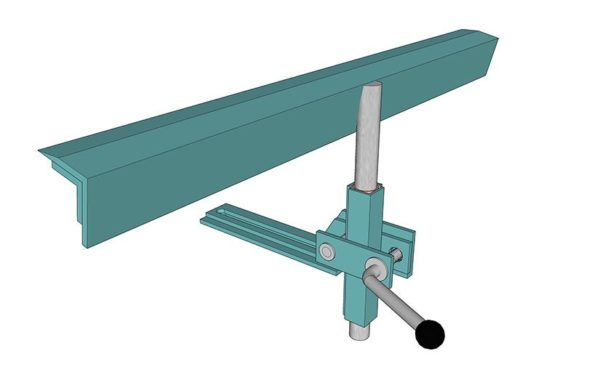
When making a bracket for a handrest, it is desirable to provide not only horizontal movement, but also rotation around the mounting axis. Vertical movement is not required, except for a slight adjustment. The support plane must be in the same horizon with the axis of rotation of the workpiece.
Machine drive
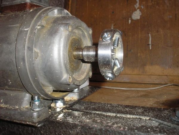
Actually, the engine that rotates the workpiece. The easiest option is direct transmission. The spindle is fixed directly to the motor shaft, no transmission devices are provided. 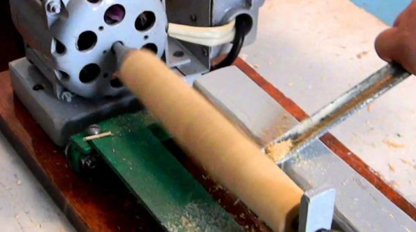
Advantage - simplicity of design, no need to look for additional details. In addition, the engine placed directly on the frame saves space. There are also disadvantages.
Firstly, - it is impossible to regulate the speed (unless you found a motor with a regulator). Secondly, the load will constantly act on the shaft. In addition to harmful vibrations, bearings will wear unevenly. Electric motors are equipped with conventional, so-called. running bearings. They are not designed for longitudinal loading.
However, when machining medium to large workpieces, shaft loads can be critical. Therefore, it is advisable to provide a separate unit for the spindle (the design is called the headstock), and apply the torque using pulleys and a belt drive. 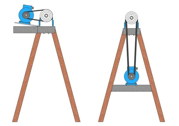
- Yes, this creates additional design difficulties, but they are offset by advantages: firstly, the engine runs in a gentle mode, and secondly, using a set of pulleys, you can adjust the speed without losing power.
- Wood lathe spindle. A fixing element that transmits torque to the workpiece. It can be a simple stop with teeth against slipping, or have fixing screw clamps (the design is called a faceplate).
Important! Any speed controller (read supply voltage) results in loss of motor torque.
A device that supports the workpiece on an imaginary axis of rotation. It can be a simple bolt with a conical sharpening (although there will be high friction at the attachment point). Or the emphasis can be made on the support bearing.
Then the workpiece will be more whole, and the rotation will be smoother.
If desired, you can find a finished part from a decommissioned lathe. 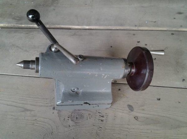
Important! The centers of the headstock and tailstock, as well as the plane of the handpiece, must match. Otherwise, processing of the workpiece will not be possible.
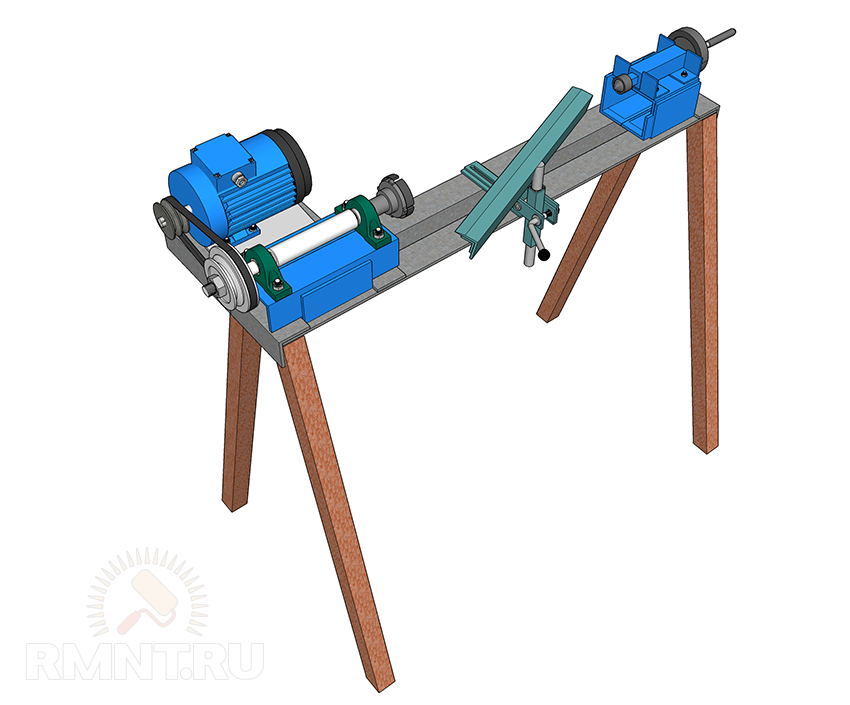
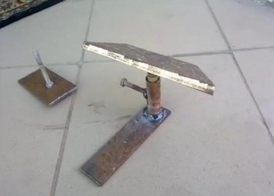
Ideally, a homemade wood lathe should look like this: 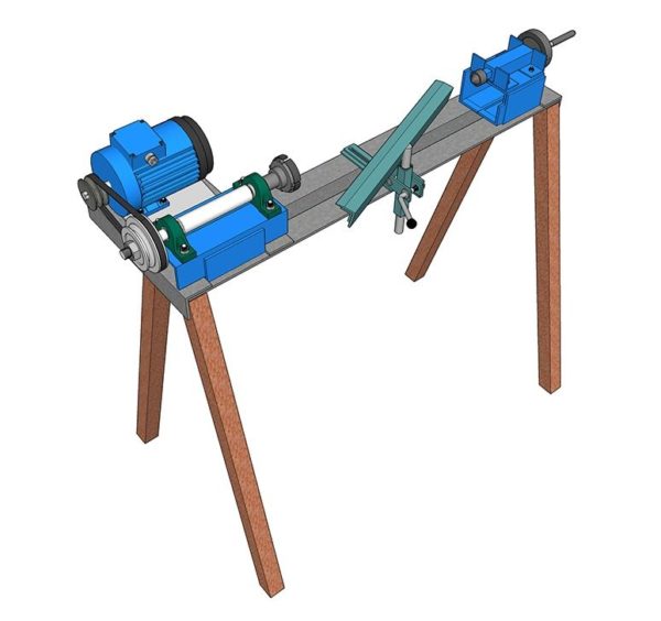
It is only necessary to ensure stability, since the lateral force during processing can be high, and the machine can be overturned.
A simple wood lathe from a channel and an electric motor, see the details in this video.
If you work on a workbench, the bed is screwed to the tabletop. Then the legs are not needed. You can generally do without a frame - then all the elements are screwed to the workbench once and for all, and no longer move. 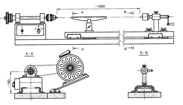
Perhaps they will seem redundant, but it is better, as they say, to “overdo it”.
- The workpiece must rotate on you (and therefore on the cutting edge of the tool)
- Before starting processing with cutters, it is necessary to give the workpiece a shape close to cylindrical (of course, if possible). To do this, you can use a rasp, pressing it with a plane
- It is safer to press the cutter against the workpiece not at a straight line, but at an acute angle. Then, as you shape it, without lifting it from the surface, draw the corner on a straight line
- No need to try to get smooth surface with a cutting tool. Grinding is done sandpaper. Just remember to wear gloves - friction can burn your hands
- Hard woods are processed at high speeds, soft woods at low speeds.
Entry level machine
If the considered design is too complicated, let's return to the option of how to make a wood lathe from a drill or screwdriver. Of course, the elements artistic decoration do not grind on such equipment. But making a handle for a file or a frying pan is easy.
It is enough to fix the drill on a flat base with a clamp for the neck of the tool. On the contrary, strictly coaxially, install the tailstock. 
Of course, there is no need to strive for an aesthetic ideal, as in a sketch. The main thing is that the design is durable and comfortable. 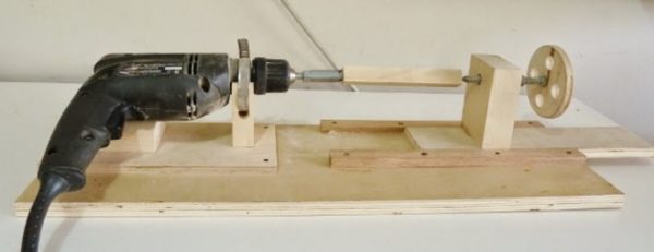
And finally, the main bonus - the drill can still be used for its intended purpose.
We make a wood lathe from a drill with our own hands, tips and tricks for manufacturing.
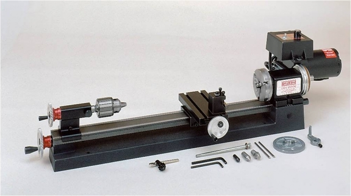
Now you can buy a lathe for wood and metal for every taste (and for any cost). Of course, they add to the machine a lot of the most modern and additional functions (which most often are not needed).
I do not argue the lathe is a very necessary and useful thing for the workshop, but in 90% of cases it is not worth the money spent on it.
We want to help you save your finances. Why buy a model with a lot of unnecessary features when you can make your own standard simple model?
wood lathe materials
The design itself consists of the following parts (see the figure)
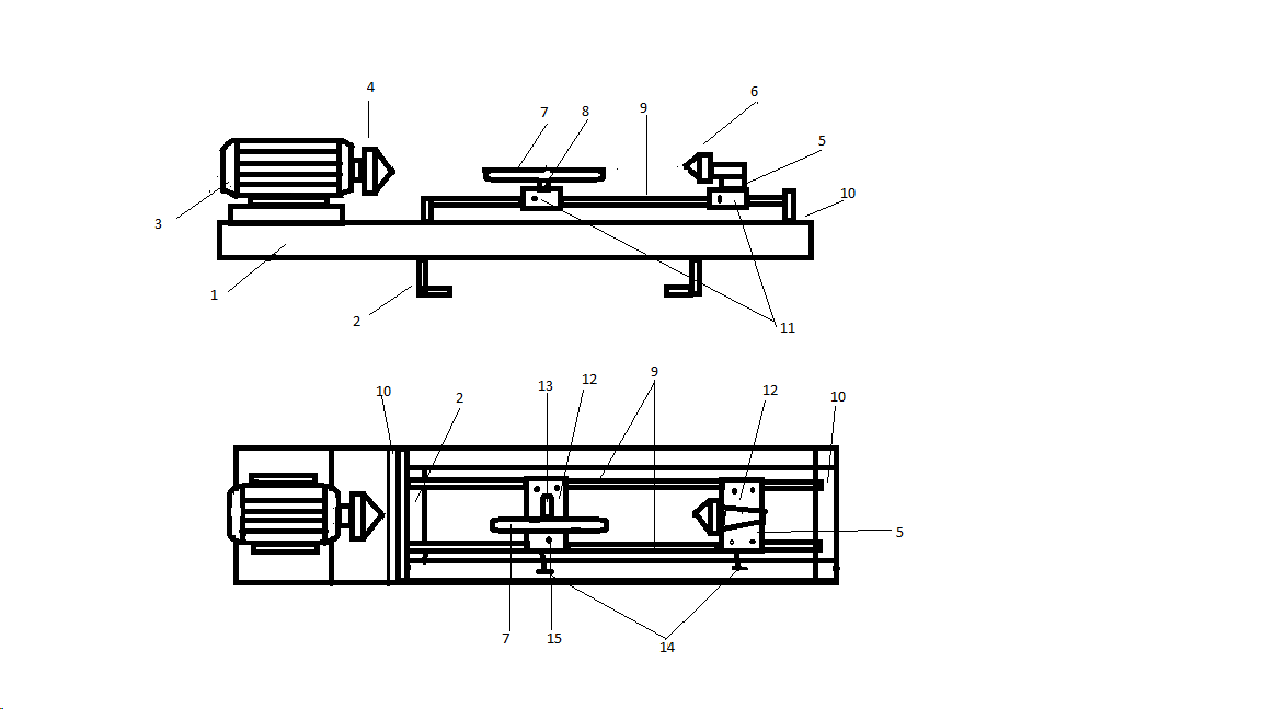
- Bed - is the basis for the machine, usually made of metal and consists of several connected beams.
- Cross P - shaped beam.
- Electric motor - serves as a power source for the correct movement around its axis (single-phase motors with a power of 200-400 watts are suitable).
- Scroll chuck.
- Support for tailstock.
- The element that is spinning.
- An emphasis for preparation or the tool.
- Emphasis for a handyman.
- Guide beams.
- Angle, stand or support for the tailstock.
- Clip.
- Metal plate for support.
- Detail of the cross rail.
- Screws for fastening.
- Base axle.
Wood lathe step by step instructions
First of all, you can not buy a new motor, but take a used one, it will cost you much less. 
The elements are fixed on the basis (No. 1 in Fig.) 2 p-shaped beams are connected by welding with two transverse ones (No. 2 in Fig.).
The guides from above are additionally fixed with two corners (No. 10 in the figure), which are fixed to the main surface.
The engine (No. 3 in the figure) is attached to the side and the headstock is fixed. 
As the basis of the tailstock, it is worth using a rotating center (buy a part from the purchased option), fix it to the support (No. 5 in the figure) and weld it on the site (No. 12 in the figure)
The stop (No. 5) is made from a corner and is attached to the support (No. 8) which itself is fixed to the clip. The stop and clip are strung on the support axle (No. 15) and then welded to the guide beams. 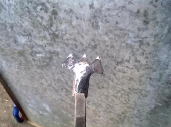

The same stop (No. 5) and the rotating element (No. 6) are fixed on metal plates (No. 12) which contain special moving clips (No. 11).
Please note that the stop and tailstock are moving elements that should move along the guides (No. 9) without problems.
In order for the moving elements to be well attached to the clips, preliminary holes are made in the clips (No. 14) and the slightest inaccuracy reduces the quality of the entire apparatus. 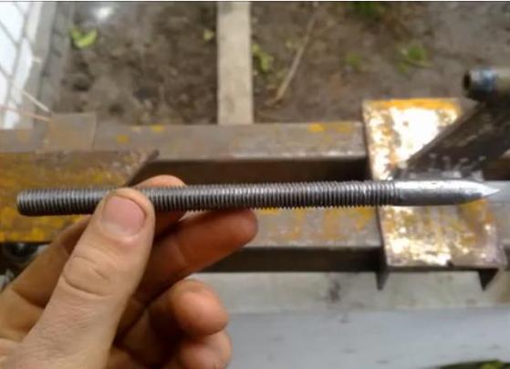

Welding itself can lead to deformation of the material - first, all materials are fastened together by spot welding, and then they carry out the full work.

![]()
Wood lathe video
metal lathe materials

To make such a tool, you will need:
- Metal sheet;
- P - shaped metal beams;
- Steel strips;
- Steel corners;
- Electrical engine;
- transmission mechanism;
- Several nuts and bolts for fastening;
- Bulgarian;
Separately, it is worth mentioning the engine, it does not have to be new, you can limit yourself to old or used ones, its power should be 2 kW with a number of revolutions per minute within 2000. Although this depends more on the level of your work on this machine.
The more massive the workpiece - the more powerful the engine should be, if you want to make a compact machine with low power - a motor even from a washing machine or an electric drill will do.
As for the transmission mechanism, you can find it on the Internet or buy an old gearbox from friends and remove the clutch from the gearbox. Thus, you will get a mechanism that creates several speeds for your machine. And if you install an additional pulley, you can improve the number of revolutions.
Metal lathe step by step instructions
The installation should start with the use of steel corners and a U-shaped beam, of which (1 corner and 1 beam) you need to weld the frame for the base.
To do this, you need to wedge the base. Guides are assembled from square pipes and steel strips.
In addition to this, their sheet metal make a box for the chuck, after installation, adjustable bearings are placed in it.
The tailstock must be welded from a corner and a thick plate, which will be supported by guides.
The headstock should move easily, freely along the guides. Weld nuts to the top of the headstock (to fix the supporting center).
The sharpened cone should be mounted in the beam, while maintaining maximum accuracy. Such a cone can be made from any bolt that suits your size.
After that, the entire structure is assembled, checked for ease of rotation of the spindle, adjusting the front and posterior centers to create an even axis.
Now you know that building a machine for wood or metal is quite realistic and requires little knowledge and effort from you, and at the same time it will cost you much less (and even if it breaks, you can fix it yourself).
In general, the manufacture of such a machine will help you even if you do not often do such work, the only such mechanisms are very bulky and you need a place to store them (or you can make "pocket" models).
Metal lathe video
A homemade lathe in most cases successfully replaces expensive factory fixtures. Especially when there is a desire to process metal with minimal cost for equipment.
It is not difficult to make a small desktop lathe with your own hands, or you can choose a more complicated drawing for a garage. The cost of parts and materials is affordable, some spare parts are likely to be found on the farm.
Main elements and principle of operation
One of the most important characteristics of a metal lathe is the ability to withstand the severe loads that occur during metal processing. At the same time, accuracy and speed are required.
A simple design for metal processing at home contains:
- base (frame);
- two racks (they are grandmas);
- electric motor;
- movement transmission mechanism;
- fixture for fixing the workpiece;
- stop for the cutter (caliper).
The main mechanisms are placed in, but the motor homemade design may be outside. With the help of the transmission mechanism, the movement from the engine is transmitted to the spindle - a hollow shaft, to which the workpiece is attached using a chuck. tailstock serves to maintain the free end of the part.
Machining precision is achieved not only by skillful hands:
- foundation stability;
- lack of "beating" of the spindle;
- reliable fastening of the workpiece in the chuck.
Made in accordance with all the rules, the mini-machine is easy to operate and compact. It is suitable for processing small metal parts various shapes, blanks made of wood, plastic.
Selection of parts
When the drawings of all components and fixtures are developed, you can begin to select parts.
Base

The purpose of the frame is a rigid fixation of the leading and driven centers. For a desktop mini-machine, you can do it yourself from a wooden block. This design will withstand work with small metal parts. A stationary frame for a garage or workshop must be durable, it is welded from a corner, metal strips or a channel. It is recommended to use factory-made guides. In the absence of them, they are assembled from rolled metal with their own hands.
The dimensions of the bed determine the dimensions of the parts to be processed. So, the length of the workpiece depends on the distance between the faceplate (chuck) and the center of the tailstock.
Electric motor and transmission
Most suitable for homemade machine — asynchronous motor. Its feature is constant speed rotation. To process metal blanks, the following power is required:
- for work with small workpieces made of soft metals - 0.5 - 1 kW;
- for working with large parts and steels - 1.5 - 2 kW.
A motor from a high power electric drill is quite suitable.
The use of collector motors whose rotation speed depends on the load should be avoided. Accelerating at idle, it can lead to ejection of the workpiece from the chuck and injury to the hands. If there is no other engine, the collector must be supplemented with a gearbox that controls the speed under any load.
The transmission can be used belt or gear. It is easier to assemble a belt with your own hands, it is quite reliable. The belt levels the force directed along the shaft and destroying the bearings of the electric motor.
You can also use a gearbox that will allow you to work at several speeds. And you can increase the engine speed with the help of an additional pulley.
An alternative to the transmission mechanism is to mount the tool chuck directly on the motor shaft. Such a device is often used for desktop mini-machines assembled from a drill or a hand-held engraver. When planning it, you need to choose an engine with a sufficiently long shaft! To partially compensate for the load along the shaft, a stop is installed between its end and the rear surface of the housing, for example, in the form of a ball.
Master and slave centers

In order for the part to rotate smoothly and not vibrate, the centers must be located strictly on the same axis. The workpiece is fixed with a faceplate or cam chuck.
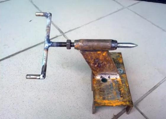
The driven center is located on the rear support and can rotate or be stationary. A threaded hole is made in the support and a bolt is screwed in, which is sharpened under a cone. The bolt should have a stroke of about 3 cm in order to firmly press the inserted workpiece. The rear support (headstock) moves along the base along the guide. But in the simplest mini-machines, the end of the workpiece is supported by a retractable sharpened threaded pin, the amplitude of which is small.
Machine assembly process
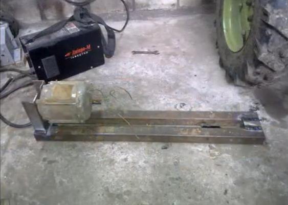
We take an old working drill as the basis for the design.
- We weld a base 70 cm long from corner No. 40: there are two long corners along the edges, two between them - 40 cm long - this is the length of the working area. We leave a gap between the short corners - the guide.
- The headstock in this case is a stand in which you need to conveniently and securely fix the drill. Let's make it from metal corner and plates. In the vertical part we cut a round hole for a drill chuck. The cartridge must fit snugly into the hole.
- We weld the headstock to the base on the corner.
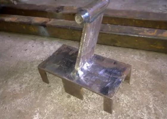
- The base for the tailstock is cut from the No. 100 corner. In the center of the horizontal part of the corner, we drill a hole for a bolt that runs along the guide and holds the headstock. From below, the bolt is welded to a rectangular pressure plate, from above it is adjusted with a nut.
The caliper or tool post will move along the center guide. For the manufacture of a caliper, you will need a cast-iron blank with a diameter of 80 mm, from which 2 parallelepipeds are cut out with a grinder. We cut holes in them for bushings with a diameter of 22 mm. We will make the rods from the axle shafts of the passenger car found in the garage.
The base and side parts are cut out of a metal plate. We weld a bronze nut between the rods, pressed into a steel sleeve, where we screw in a threaded pin passing through a hole in one of the sidewalls. Here we weld homemade pen or lamb. We drill a vertical hole with a thread in the movable part with our own hands. On a long bolt we weld a plate - a tool holder. We pass the bolt through a square plate mounted on bearings and screw it into the moving part of the caliper. Along the perimeter of the plate, we will make clamps for the tool holder from bolts.
Common disadvantages of homemade lathes
- Low power of the electric motor, which does not allow to achieve sufficient performance of the mini-machine;
- small spindle diameter, limiting the size of the workpiece;
- lack of automation, so all settings are displayed by hand;
- limiting the maximum dimensions of blanks;
- vibrations due to fragile frame.
The first video clearly shows the design of the caliper, the second video shows another model of a do-it-yourself homemade lathe:


How to understand: will the kitten be fluffy?
What kind of light alcohol can be drunk for pregnant women: the consequences of drinking
Why do the legs swell in the ankles and ankles of the feet in pregnant women: causes and methods of treatment
The wedding of Prince Harry and Meghan Markle: scandalous and secret details of the marriage (photo) The future marriage of Prince Harry year NTV
How to close white plums for the winter