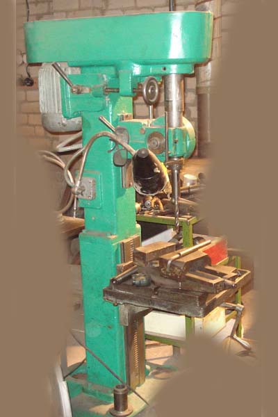
Vertical- drilling machine 2H118 is a universal unit, its power amazes specialists and lovers of precision drilling.
The 2n118 drilling machine is designed for such actions as drilling, countersinking, reaming holes, as well as trimming the ends of parts, provided that a special nozzle is used.
The main area of use is medium and small enterprises, where products are produced in small batches. Forge equipment - Molodechensky plant MSZ, Republic of Belarus.
During the drilling operation, the rotational movement of the head and the spindle on the driving base come into action. As you can see, the mechanism is quite simple, nothing more. When determining the drilling parameters, indicators are taken into account for the diameter of the drilling, the length of the overhang of the spindle itself.
Brief information about the gradation of machines
Aggregate classification:
- Machining small holes up to 16.0 mm. Most often, such diameters are used in instrument making.
- Processing of medium and large diameters from 18.0 to 75.0 mm.
- for drilling large items.
- Machines for drilling high-precision diameters.
- Milling type.
- Central machines.
- Multi-spindle machines.

Characteristic advantages of the machine
Drilling machine 2n118 is designed for drilling small holes up to 18.0 mm in metal surfaces. In order to improve the quality of work, a maximum torque of 880 Nm is developed and the feed is 560 kgf. When working with each part, it is possible to select the speed and feed rate, which makes the work more accurate and efficient, reduces the risk of marriage.
Similar models:
- 2A118 layout and single-spindle head.
- 2N118F2 upgraded version with automated system management.
- 2b118 with an increased number of feed steps.
- Vertical mechanism 2N118K.

Machine 2N118K
Technical data about the product
- “T” is a shaped working surface and is equal to 32.0 × 36.0 cm.
- The movement of the surface during the revolution of the flywheel is 2.4 mm, along the vertical plane - 35.0 cm.
- The total weight of the apparatus is 450 kg.
- Distance from extreme point spindle to work surface is 65.0 cm.
- The overhang of the machine is 20.0 cm.
- The spindle head is capable of moving up to 30.0 cm.
- The working stroke of the sleeve is 15.0 cm.
- The spindle head moves 4.4 mm per revolution.
- The rotational speed (average) of the spindle is 2.4 rpm, the minimum is 200 rpm, the maximum is 2.8 thousand rpm.
- The spindle speed is controlled by nine indicators.
- The power of the electric motor shaft is one and a half kilowatts, the maximum rotation speed is 1.42 rpm.
- The maximum feed rate is 560 kgf.
- Dimensions 87.0 × 59.0 × 208.0 cm.
Among the main features is the option of spindle braking.
Equipment design
Description: the main element is a column in the form of a box - the headstock. It is installed on a metal plate - the base. The headstock moves along the rack and pinion mechanism to the sides with the help of electric drive motor.
On the front top is an electric motor. At the bottom, there is a spindle assembly with a rotation head. Inner part filled with a gearbox, which is responsible for the speed, feed rate, vertical lift. Vertical ascent and descent is provided by a special rack and pinion mechanism. And it drives this body - the steering wheel.
The workpiece is mounted on the desktop, if necessary, moves, the height is adjusted. It is regulated by a special handle on the side.
The kinematic scheme of the machine operates in the following order:
- The gearbox adjusts the feed to one of nine speeds.
- By means of a reversible drive of an electric motor it is possible to change the direction of rotation.
- The function is especially relevant when you need to cut internal thread on the details.
- The spindle is fed vertically by a rack and a toothed shaft, which is installed in the lower front part of the headstock.
- The side handle is responsible for moving the headstock along the column guides.
- The working table moves vertically due to the rotation of the handle.

Equipment controls
There are a number of elements of the unit:
- Automatic power switch.
- Toggle switch for lighting the work surface.
- The switch for the liquid supply pump to the cooling system.
- Feed adjustment handle.
- Button to activate feed.
- Feed rate selector.
- Control unit and direction of movement of the spindle.
- Drilling head speed controller.
- Bolts - clamps of the wedge of the working head.
- Handle for fixing the desktop clamp.
- Electrical contacts and network power board.
- To provide auxiliary control, a number of buttons, a starting machine, a manual starter are used.
Spindle stop
For braking efficiency, the machine uses a dynamic circuit. Direct current is supplied to the three phases of the winding through the contact group.
During the implementation of the stop, speed reduction, the windings of two phases are shorted. A full stop occurs when you press the corresponding button.
Electrical protection
To prevent unwanted overloads, the manufacturer provides protection - circuit breaker AST - 3. Grounding of the machine is provided by a coil of magnetic starters. The drill, as well as the contact board, must be connected in accordance with the requirements and standards that apply to production equipment.
Components of the electrical part: electric power unit, electric pump for supplying liquid to the cooling system, start-up mechanisms and automatic shutdown, rectifiers, spot light to improve workflow.
Without fail, each employee, especially who works at the machine, must strictly comply with the norms and requirements of the labor protection instructions. Otherwise, the worker is not allowed to work.
Purpose of drilling machines
Drilling machines are designed for drilling blind and through holes in solid material, reaming, countersinking, reaming, cutting internal threads, cutting discs from sheet material. To perform such operations, drills, countersinks, reamers, taps and other tools are used. The shaping movements in the processing of holes on drilling machines are the main rotational movement of the tool and the translational movement of the tool along its axis.
The main parameter of the machine is the largest nominal diameter of drilling a hole (for steel). In addition, the machine is characterized by overhang and the largest spindle travel, speed and other indicators.
Classification of drilling machines
Drilling machines are divided into the following types:
- Vertical drilling machines;
- Single spindle semi-automatic;
- Multi-spindle semiautomatic devices;
- Coordinate boring machines;
- Radial drilling machines;
- Horizontal boring;
- Diamond boring;
- Horizontal drilling machines;
- Different drilling.
Machine models are designated by letters and numbers. The first digit indicates which group the machine belongs to, the second - to which type, the third and fourth digits characterize the size of the machine or the workpiece being processed. The letter after the first digit means that this machine model has been upgraded (improved). If the letter is at the end, then this means that a different machine was made on the basis of the main model.
For example, the machine model 2H118 is a vertical drilling machine, the maximum diameter of the machined hole is 18mm, improved compared to the drilling machines models 2118 and 2A118. The machine model 2H118A is also vertical drilling, the diameter of the processed hole is 18 mm, but it is automated and designed to work in small-scale and mass production.
Depending on the field of application, a distinction is made between universal and special drilling machines. Specialized drilling machines for large-scale and mass production are also widely used, which are created on the basis of universal machines by equipping them with multi-spindle drilling and thread-cutting heads and automating the work cycle.
Of all the drilling machines, the following main types of universal machines can be distinguished: single and multi-spindle vertical drilling; radial drilling; horizontal drilling for deep drilling.
Manual drilling machines
Vertical drilling machine.
Rice. 1. Vertical drilling machine:
1 - column (bed); 2 - electric motor; 3 - drilling head; 4 - handles for switching gearboxes and feeds; 5 - manual feed wheel; 6 — limb for controlling the depth of processing; 7 - spindle; 8 - hose for coolant supply; 9 - table; 10 - table lifting handle; 11 - foundation plate; 12 - electrical cabinet.
On the frame 1 of the machine are the main components. The bed has vertical guides along which the table 9 and the drilling head 3 move, carrying the spindle 7 and the electric motor 2. The workpiece or fixture is installed on the table 9 of the machine, and the alignment of the hole in the workpiece and the spindle is achieved by moving the workpiece.
The gearboxes and feeds are controlled by handles 4, manual feed - by the handwheel 5. The depth of processing is controlled by the limb 6. The counterweight is placed in a niche, the electrical equipment is placed in a separate cabinet 12. The foundation plate 11 serves as a support for the machine. In medium and heavy machines, its upper plane is used for setting workpieces. The coolant is supplied by an electric pump through hose 8. The drill head assemblies are lubricated with a pump, the remaining assemblies are lubricated manually.
The drilling head 3 is a cast iron, in which the gearbox, feed mechanisms and spindle are mounted. The gearbox contains two- and three-crown blocks of gears, by switching which, using one of the handles 4, the spindle receives various angular speeds. The spindle speed, as a rule, changes in steps, which is provided by a gearbox and a two-speed electric motor 2.
In contrast to vertical drilling, in a radial drilling machine, the axes of the hole in the workpiece and the spindle are combined by moving the spindle relative to the stationary workpiece in the radial and circular directions (in polar coordinates). By design, radial drilling machines are divided into machines general purpose, portable for processing holes in large workpieces (machines carry crane to the workpiece and process vertical, horizontal and inclined holes) and self-propelled, mounted on trolleys and fixed with shoes during processing.
CNC drilling machines
CNC vertical drilling machine.
 Rice. 2. CNC vertical drilling machine:
1 - stand-alone CNC rack; 2 - cabinet of power electrical equipment; 3 - turret; 4 - table; 5 - stepper motor; b, 7, 8, 11 - control units; 9 - code converter; 10 - reader.
The machine is designed for drilling, countersinking, reaming, threading and light straight-line milling of parts made of steel, cast iron and non-ferrous metals in small-scale and mass production. Turret 3 with automatic tool change and cross table 4 allow for coordinate processing of parts such as flange covers, panels without preliminary marking and the use of conductors.
Shortcut http://bibt.ru
Vertical drilling machines 2118; 2135; 2150. Drill head with various tools.
Vertical drilling machines 2118; 2135; 2150 are used when drilling holes with a diameter of up to 50 mm.
The first two digits indicate the type of machine, and the last - largest diameter drilling.
On fig. 129 shows the single spindle vertical drilling machine 2150 and its kinematic diagram. It consists of a single-column vertical frame 1, mounted on a foundation plate 2. An electric motor 3, a gearbox and a gearbox 4 are installed on the frame, with the help of which the spindle 5 receives six speeds from 46 to 475 rpm and ten feeds from 0.15 to 0.30 mm per revolution.
During drilling, the parts are installed and fixed on the table 6. The feed of the drill 7 on this machine can be carried out manually with the steering wheel 8 or automatically using the gearbox and the feed box. The table is raised and lowered by turning the handle 9. The machine is turned on using the buttons located on the shield.
Drilling heads are often mounted on the spindle of vertical drilling machines (Fig. 130), allowing drilling with five tools in one setting, for example, drilling, threading, reaming. Thus, a single-spindle machine with such a head can replace a five-spindle one, but the part does not need to be rearranged.
Rice. 129. Single spindle vertical drilling machine.
Information about the manufacturer of the vertical drilling machine 2118
The manufacturer of the vertical drilling machine 2118 is the Novocherkassk Machine Tool Plant, founded in 1938.
Since January 1957, the plant has specialized in the production of only turret machines. The plant produced turret lathes: 1N318, 1N325, 1G325, 1D325, 1E325, 1325F3.
2118 vertical drilling single-spindle universal machine. Purpose and scope
Universal vertical drilling machine model 2118 with conditional diameter drilling 18 mm is designed to perform the following operations: drilling, reaming, threading and cutting ends with knives.
The machine is designed to work in the main production shops, as well as in the conditions of single and small-scale production in tool, experimental, mechanical repair and tool shops with individual output.
Main Specifications of 2118 Table Drilling Machine
Manufacturer - Novocherkassk Machine Tool Plant.
The main dimensions of the machine correspond to - GOST 1227-79.
- Maximum drilling diameter: Ø 18 mm
- Maximum drilling depth: 150 mm
- The highest height of the workpiece installed on the work table: 500 mm
- Spindle RPM Limits - (6 steps) 300..3100 rpm
- Spindle end - Morse 2
- Motor power: 1,0 kW
- Machine weight: 450 kg


Kinematic diagram of the drilling machine 2118
The design of the drilling machine 2118
By its design, the drilling machine is very easy to operate. In order to set the selected drilling speed, it is necessary to rearrange the V-belt to the appropriate pulley step.
In order to transfer the belt from one step of the pulley to another, it is necessary to unscrew the special handle on the bracket and, by turning the screw to the left, move the bracket together with the electric motor towards you. After that, it is necessary to rearrange the belt, and then (to tension the belt) by turning the screw to the right, move the bracket with the electric motor away from you.
Automatic feeding is carried out through the feed box, the roller of the latter is driven from the spindle flare through a small gearbox, which is connected to the flask by a belt.
The amount of automatic feed is 0.2 mm per spindle revolution. Feed more than 0.2 mm. can only be done manually, for which a special overtaking mechanism is arranged in the feed box.
In order to work with a feed of less than 0.2 mm (when drilling in steel up to Ø 6 mm), the automatic feed must be turned off by retracting the handle counterclockwise until it stops and turn the stop screw on the side of the disk.
In order to automatic feeding to drill to a predetermined depth, there is a movable stop bar on the shift sleeve disk, and a special scale in millimeters is applied around the circumference of the vernier ring, according to which the predetermined depth is read. The bar is set according to the required drilling depth.
The machine is started and stopped by means of an electric motor, and the latter is turned on and off by a drum switch.
Automatic feed 0.2 mm. can be applied for carbon steel, for drilling diameters from Ø 6 mm to 18 mm. For cast iron, for drilling diameters from 3 mm. up to 18 mm.
When working with automatic feed, the handle must be set to the middle position.
The ease of turning off the automatic feed is carried out by selecting the rollers in the feed box: Ø 12.3..12.7.
Drilling machine cooling 2118
To cool the tool during drilling, a special P22-A type electric pump is mounted on the machine, which can be switched on using a separate package switch.
A special reservoir is provided for the coolant in the cabinet of the machine.
Drill Lubricant 2118
The machine is lubricated daily before starting work in the following places:
The axis of the feed gear is through two oilers on the feed box housing.
With automatic feeding, it is necessary to generously lubricate the neck of the feed roller of the feed box - through the circular chamfer in the bushing of the feed box.
All other mechanisms are lubricated periodically by stuffing grease through holes specially provided for this purpose.
The lenix bearing is lubricated periodically by unscrewing the roller from the bar (left-hand thread). Feed roller bearings are lubricated through the hole in gear Z63 by unscrewing the locking screw.
Gearbox drive gears need to be lubricated daily.
Lubrication of the rack and pinion gearing of the feed box is carried out by applying oil to the teeth of the quill.
The worm gear axle in the table lift mechanism is lubricated through an oiler at the end of the axle.


Electrical equipment and electrical circuit of the drilling machine 2118

Wiring diagram drilling machine 2118
2118 vertical drilling single-spindle universal machine. Video.
Machine Specifications 2118
| Parameter name | 2n118 | 2118 |
|---|---|---|
| Main parameters of the machine | ||
| Maximum drilling diameter, mm | 18 | 18 |
| The smallest and largest distance from the end of the spindle to the table | 0...650 | 0...650 |
| Distance from the axis of the vertical spindle to the rack guides (outreach), mm | 200 | 200 |
| Desktop | ||
| Dimensions of the working surface of the table (length x width), mm | 360 x 320 | 350 x 340 |
| Number of T-slots Dimensions of T-slots | 3 | 3 |
| The greatest vertical movement of the table (Z axis), mm | 350 | 445 |
| Table movement per turn of the handle, mm | 2,4 | |
| Spindle | ||
| The greatest movement of a spindle head, mm | 300 | 150 |
| Movement of the spindle head on one turn of the handwheel, mm | 4,4 | |
| Spindle sleeve stroke, mm | 150 | |
| Spindle displacement by one division of the limb, mm | 1 | |
| Spindle travel per turn of the handwheel-handle, mm | 110 | |
| Spindle speed, rpm | 180 - 2800 | 300, 450, 735, 1200, 1980, 3100 |
| Number of spindle speeds | 9 | 6 |
| The highest allowable torque, kg * cm | 880 | |
| Spindle taper | Morse 2 | Morse 2 |
| Machine mechanics | ||
| Number of steps of working giving of a table | 6 | 1 |
| Limits of vertical working feeds per spindle revolution, mm/rev | 0,1 - 0,56 | 0,2 |
| Maximum allowable feed force, kgf | 560 | |
| Spindle braking | there is | |
| Drive unit | ||
| Main Drive Motor Type | AOL2-22-4S2 | A-41/6 |
| Electric motor of the drive of the main movement Number of revolutions per minute, rpm | 1420 | 930 |
| Main drive electric motor Power, kW | 1,5 | 1,0 |
| Electric coolant pump Type | PA-22 | PA-22-A |
| Dimensions and weight of the machine | ||
| Machine dimensions (length width height), mm | 870 x 590 x 2080 | 875 x 550 x 2005 |
| Machine weight, kg | 450 | 450 |


History of sky lanterns
Job description: concept, purpose, structure, procedure for compiling and formalizing Purpose and content of job descriptions for managers
Interview questions What job are you going to work on?
What to do if the boss criticizes all the time If the boss does nothing
How to understand: will the kitten be fluffy?