Manual programming on
G-codes.
Terms
Computer numerical control(CNC) - computerized system
control, drive control
technological equipment,
including machine tools.
History of CNC
The inventor of the first machine tool with a numerical (program)control (Eng. Numerical Control, NC) is John
Parsons (John T. Parsons), who worked as an engineer in the company
his father's Parsons Inc, which produced at the end of World War II
war propellers for helicopters. He first proposed
use a machine to process propellers,
working according to the program entered from punched cards.
History of CNC
In 1949, the US Air Force funded ParsonsInc machine development for
contour milling of complex parts
aviation technology. However, the company was unable
to carry out the work independently and applied for
help to the laboratory
servomechanics at MIT
Institute (MIT). Parsons Inc collaboration with MIT
continued until 1950. In 1950, MIT acquired
milling machine company HydroTel and refused to cooperate with Parsons Inc,
having signed an independent contract with the US Air Force for
creation milling machine with software
management.
In September 1952, the machine was for the first time
demonstrated to the public - about him was
published an article in Scientific American. Machine
controlled with punched tape.
The first CNC machine was particularly complex and
could not be used under production conditions.
The first serial CNC device was created
by Bendix Corp. in 1954 and since 1955 it has become
installed on machines. Widespread introduction of machine tools
CNC was slow. Entrepreneurs with distrust
dealt with the new technology. Ministry of Defence
The United States was forced to manufacture 120
CNC machines to rent out to private
companies.
History of CNC
The first domestic CNC machinesindustrial applications are the 1K62PU screw-cutting lathe and the 1541P lathe. These machines were created in
the first half of the 1960s. The machines worked
together with control systems such as PRS3K and others. Then they developed
CNC vertical milling machines 6H13 with
control system "Kontur-ZP".
In subsequent years for turning
machine tools are most widely used
domestic CNC systems
production 2R22 and Elektronika NTs-31.
CNC equipment can be represented by:
machine park, for example machines (machines,equipped with numerical software
controlled, are called CNC machines):
– for metal processing
(e.g. milling or turning), wood,
plastics,
- for cutting sheet blanks,
– for pressure treatment, etc.
drives of asynchronous electric motors,
using vector control;
characteristic control system
modern industrial robots.
The CNC abbreviation corresponds to two English-language ones - NC and CNC - reflecting the evolution of the development of equipment control systems.
The CNC abbreviation corresponds to twoEnglish-speaking - NC and CNC, - reflecting the evolution
development of equipment control systems.
Systems such as NC (English Numerical control), which appeared first,
provided for the use of rigidly defined control schemes
processing - e.g. programming with plugs or
switches, storage of programs on external media. Any
random access storage devices, control processors are not
provided.
More modern systems CNC, called CNC (eng. Computer numerical
control) - control systems that allow you to use for modification
existing / writing new programs software tools. base for
CNC constructions serve as a modern (micro)controller or
(microprocessor:
–
–
–
microcontroller,
programmable logic controller,
microprocessor-based control computer.
It is possible to implement a model with a centralized automated
workstation (for example, ABB Robot Studio, Microsoft Robotics Developer
Studio) and then downloading the program via transfer via
industrial network
10.
11.
12.
13.
14.
15.
16.
17.
1 - screw-cutting,2 - turning and revolving,
3 - lobotocarny,
4 - turning and rotary,
5, 6 - horizontal boring,
7- console
horizontal milling,
8 - console
vertical milling,
9 - longitudinal milling
vertical,
10 - longitudinal milling,
11- longitudinal milling
with movable portal
12- single column
planer
18.
Numerical control (CNC) of the machine - control of the processing of the workpiece on the machine according toUE, in which the data is given in digital form.
Numerical control device (CNC) - a device that issues control
impact on the executive bodies of the machine in accordance with the UE and information on the state
managed object.
NC block (block) - component UE, introduced and developed as a single
integer and containing at least one command.
For example, N10 G1 X10.553 Y-12.754 Z-10 F1500;
UE word (word) - an integral part of the UE frame containing data on the parameter of the processing process
blanks and other control execution data.
For example, F3000 - move speed setting;
CNC address (address) - part of the NC word that determines the purpose of the data following it,
contained behind it in the word.
For example, X, Y, Z, etc. - addresses of movement according to the corresponding coordinates;
UE frame format (frame format) - a conditional record of the structure and arrangement of words in the UE frame with
the maximum number of words.
Absolute dimension - a linear or angular dimension specified in the NC and indicating the position
point relative to the accepted reference zero.
Relative size - a linear or angular size specified in the UE and indicating
position of the point relative to the coordinates of the point of the previous position of the working body of the machine.
Part zero point (part zero) - a point on the part, relative to which its dimensions are specified.
Machine zero point (machine zero) - a point that defines the origin of the machine coordinate system.
Interpolation - obtaining (calculation) coordinates of intermediate points of the trajectory of the movement of the center
tool in a plane or space.
Tool center - a fixed point of the tool relative to the holder, along which
trajectory calculation;
19.
20. There are three methods for programming machining for CNC machines:
There are three methodsprocessing programming
for CNC machines:
manual programming
CNC programming
programming with
CAD/CAM systems.
21. programming methods for CNC machines
Manual programmingis pretty
a tedious task.
However, all programmer technologists must
have a good
idea of technology
manual programming
no matter how the
actually they work.
It's like elementary school
at school, teaching
which gives us the basis for
subsequent
education. In our
the country still exists
many enterprises,
which is used
manual method
programming.
Indeed, if the factory
has several machines
CNC, and manufactured
the details are simple then
competent programmer
quite capable
work successfully without
automation tools
own labor.
Programming Method
CNC console purchased
particular popularity in
last years. It's connected
with technical development
CNC systems, improving them
interface and features.
In this case, programs
created and entered directly
on the CNC stand using
keyboard and display.
Modern CNC systems
really allow
work very efficiently.
For example, a machine operator
can produce
UE verification or choose
required canned cycle
with the help of special
icon and paste it into
UL code. Some systems
CNC offer interactive
programming language,
which is significantly
simplifies the creation process
UE, does "communication" with the CNC
operator friendly
Programming with
CAD/CAM system allows
"raise" the writing process
processing programs for more
high level. Working with
CAD / CAM system, the technologist saves himself from
time-consuming mathematical
calculations and receives
tools, much
increasing speed
writing UP.
22. Manual programming
G-code is a code name for a programming language.CNC devices (Computer Numerical Control).
Created by the Electronic Industries Alliance at the beginning
1960s The final revision was approved in February 1980
year as RS274D standard. ISO committee approved G-code as
ISO 6983-1:1982 standard, State Committee for Standards of the USSR -
as GOST 20999-83. In Soviet technical literature G-code
denoted as ISO-7 bit code.
Control system manufacturers use G-code in
as a base subset of a programming language,
expanding it as you wish.
A program written using G-code has
rigid structure. All control commands are combined into
frames - groups consisting of one or more commands.
The program ends with an M02 or M30 command.
23. "Dictionary" of the programming language G-code
24.
Machine movementsBasic movements are movements executive bodies machine, thanks to
which directly carries out the process of chip removal by the cutting
tool from the workpiece.
Auxiliary movements in machines are not connected
directly with the cutting process, but provide
preparation for its implementation.
The main movement in the machine is the movement that determines the speed
cutting, i.e., the rate of chip removal from the workpiece. The main movement can be
rotary or straight.
Workpiece clamping
The feed motion made by the workpiece or the tool, or both, is
such a movement in the machine, which ensures the supply of more and more new sections to the tool
blanks for removing chips from them. In this case, there can be several feed movements in the machine and among
they can be, for example, longitudinal, transverse, circular, tangential feed
Fixing the cutting tool
Removing the workpiece or replacing it
Changing the cutting tool
Instrument movements for automatic dimensional control
Division movements are implemented to implement the required angular (or linear) movement
workpiece relative to the tool. The dividing movement can be continuous (in
gear shaping, gear hobbing, gear cutting, backing and other machines) and intermittent
(for example, in dividing machines when cutting strokes on a ruler). intermittent movement
carried out using a ratchet wheel, a Maltese cross or a dividing head
Approach of the tool to the surfaces to be machined and
his recusal
Movements related to setting up and setting up the machine
The rolling movement is the coordinated movement of the cutting tool and the workpiece, reproducing
during shaping, the engagement of a certain kinematic pair. For example, when teething
the cutter and the workpiece reproduce the meshing of two gear wheels. Rolling motion is necessary for
shaping in gear-cutting machines: gear hobbing, gear cutting, gear shaping,
gear grinding (when processing cylindrical and bevel wheels).
A differential motion is added to any movement of the workpiece or tool. For
To this end, summing mechanisms are introduced into the kinematic chain. It should be noted that to summarize
only homogeneous movements are possible: rotational with rotational, translational with translational.
Differential movements are necessary in gear hobbing, gear cutting, gear grinding,
backing and other machines.
Coolant supply and chip removal
25.
CNC Machine Coordinate SystemsPlanar coordinate system
The rectangular coordinate system is the most common
coordinate system for CNC machines. It contains two coordinate axes
(two-dimensional system) - to determine the position of points on the plane. For
rectangular coordinate system is characterized by the following features:
coordinate axes are mutually perpendicular;
coordinate axes have a common point of intersection (origin
coordinates);
coordinate axes have the same geometric scale.
Polar coordinate system - two-dimensional coordinate system,
where each point on the plane is defined by two
numbers - polar angle and polar radius. Polar
coordinate system is especially useful in cases where
relationships between points are easier to represent as radii and
corners; in the more common, Cartesian or
rectangular coordinate system, such relationships can be
can only be established by using trigonometric
equations.
Volumetric coordinate system
Cartesian coordinate system in
space (in this paragraph we mean
three-dimensional space, about more multidimensional
spaces - see below) is formed by three
mutually perpendicular axes
coordinates OX, OY and OZ. Coordinate axes
intersect at point O, which is called
origin, on each axis is selected
the positive direction indicated by the arrows,
and the unit of measurement of segments on the axes. Units
measurements are usually (not necessarily) the same for
all axes. OX - abscissa axis, OY - axis
ordinate, OZ - applicate axis.
The position of a point in space is determined
three coordinates X, Y and Z.
Z
Y
P1
X
P2
Cylindrical coordinate system, roughly
speaking, expands the flat polar
system by adding a third linear
coordinates called "height" and
equal to the height of the point above zero
plane, just as Cartesian
the system extends to the case of three
measurements. The third coordinate is usually
denoted as, forming a triple
coordinates.
spherical
system is called coordinates
coordinates to display
geometric properties of a figure in three
measurements by specifying three
coordinates, where is the distance to the start
coordinates, and and - anti-aircraft and
azimuth angle, respectively.
26.
Depending on how many axes can be controlled at the same timeCNC system during workpiece processing, distinguish between
27.
28.
For the convenience of programming the processing process in machines withThe CNC has adopted the coordinate axes to always orientate
parallel to the machine guides. Depending on machine type
the location of the coordinate axes in space can be
different, but there are the following general rules.
1. The Z axis is always aligned with the axis of rotation of the spindle. Her
the positive direction is always the same as the direction
movement from the device for fastening the workpiece to the cutting
tool.
2. If there is at least one axis in the machine coordinate system,
located horizontally and not coinciding with the axis
spindle rotation, then it will be necessarily the X axis.
3. If the Z axis is horizontal, then positive
if you stand facing the left - relative to the front plane -
end of the machine. (The front plane of the machine is the side from which
the console and the main controls of the machine are located).
4. If the Z axis is vertical, then positive
the direction of the x-axis is the direction of movement to the right,
if you stand facing the front plane of the machine.
5. The positive direction of the Y-axis is determined by one of
the following rules:
–
Looking along the Z-axis in the positive direction,
mentally rotate the x-axis 90° clockwise around the z-axis.
29.
+Y+Z
+Y
-Z
-Y
-X
+X
-X
+X
+X
+Z
-Y
+Y
-Z
+Z
rule right hand: if you mentally place your palm
right hand to the origin so that the Z axis
came out of the palm perpendicular to it, and bent under
90 ° angle to the palm of the thumb showed a positive
direction of the x-axis, then the index finger will show
positive direction of the y-axis.
30.
ZA
X
Y
31.
With the help of the binding system, the coordinates are uniquely setposition on the plane or in the working space of the machine. Data
position coordinates are always tied to a specific point,
The machine has a rigid binding system - machine binding system,
which was set by the machine manufacturer. The user can
set any reference system for the workpiece: the CNC knows
the origin and position of this reference system relative to
machine binding systems. As a result, the CNC can
correctly transfer position data from the NC program to
workpiece.
This section describes the machine binding system.
Tool clamp point N is tough
place specified by the machine tool manufacturer
on the spindle.
Tool installation point E
it is given by the machine tool manufacturer
place of the clamping device.
32.
Before you start writing a programprocessing, for harvesting it is necessary
set anchor point, relative to
which the coordinates will be set.
At the end you can define the contour
blanks with contour functions
and coordinates in the processing program.
This binding system is called
workpiece binding system.
With binding system
coordinates are uniquely set
position on the plane or in
workspace of the machine. Data
position coordinates always
tied to a specific point
which is described in terms of coordinates.
The machine has a rigid system
bindings - machine binding system,
which was given
machine tool manufacturer. User
can set any binding system
for the workpiece: the CNC knows
origin and position of this
binding systems regarding
machine binding systems. Thanks to
this, the CNC can correctly
transfer position data from the NC program to workpieces
33.
34.
G90 - absolute positioning mode.In absolute positioning mode G90 moves
executive bodies are made relative to the zero point
working coordinate system G54-G59 (programmed where
move tool). The G90 code is canceled with the code
relative positioning G91.
G91 - relative positioning mode.
In relative (incremental) positioning mode
G91 the zero position is taken as the zero position each time
executive body, which he held before the start
move to the next reference point (programmable, on
how much should the tool move). The G91 code is canceled when
using the G90 absolute positioning code.
35.
G52 - local coordinate system.The CNC allows you to install in addition to standard working
coordinate systems (G54-G59) are also local. When the control
machine executes a G52 command, the start of the current
the working coordinate system is shifted by the value specified
using data words X, Y, and Z. The G52 code is automatically
canceled with G52 X0 Y0 Z0.
G68 - coordinate rotation.
G68 code allows you to rotate the coordinate system
to a certain angle. It takes a turn to make a turn.
Specify the plane of rotation, the center of rotation, and the angle of rotation.
The plane of rotation is set using G17 codes,
G18 and G19. The center of rotation is set relative to
zero point of the active work coordinate system (G54 G59). The rotation angle is specified with R. For example:
G17 G68 X0. Y0. R120.
36.
37.
Prerequisites for installation:geometric dimensions of the cutting part required for processing
cutting tools are measured and taken into account in control program;
the selected tools are fixed in the automatic
tool change;
tool overhangs relative to the automatic changer
tools are taken into account in the control program (if the machine is not
equipped with tool overhang correction device);
the workpiece is installed and securely fixed on the work table in
the position at which its coordinate axes are parallel to the coordinate axes
machine;
the first tool in the order of use is installed and fixed in
spindle;
spindle rotation is on.
38.
Sequence of operations when setting the workpiece zero pointon the lathe CNC
Prerequisites for installation:
geometric dimensions of the cutting part required for processing cutting
tools are measured and taken into account in the control program;
the selected tools are fixed in the clamping devices of the turret and
exposed in the transverse direction;
tool overhangs relative to the turret are measured and taken into account in
control program;
the workpiece is properly secured in the spindle.
Make sure there is no collision when turning the turret
tools with a fixed workpiece and machine parts.
Enable spindle rotation by selecting the direction of rotation corresponding to
the location of the cutting tools relative to the fixed workpiece.
Using the appropriate command from the control panel, move one of the
cutters fixed in the turret (for example, scoring) into the working
position.
Carefully bring the working tool to the outer end face free from the spindle.
surface of the workpiece, either by manual control or by
corresponding keys on the machine control panel. Touch the tip of the cutting part
tool surface of a rotating workpiece until a visually noticeable
trace and stop moving the tool.
Determine the current value of the position of the machine caliper using the CNC display system
Z axis.
Enter this coordinate value as a zero offset into the CNC and
press the key for resetting the coordinate system. If it is necessary to take into account the allowance
for processing the end surface of the workpiece, it is recommended to take it into account in advance
before entering the coordinates of the current position of the caliper into the CNC system by entering
corresponding correction to the numerical value of this coordinate.
39.
Additional features and symbolsX, Y, Z - axial movement commands.
A, B, C - commands for circular movement around the X, Y, Z axes, respectively.
I, J, K - circular interpolation parameters parallel to the X, Y, Z axes, respectively.
R
In circular interpolation (G02 or G03), R defines a radius that connects
the start and end points of the arc. In canned cycles, R determines the position
retraction plane. When working with the rotation command, R determines the angle of rotation
coordinate system.
R
With constant hole-making cycles, P determines the dwell time at the bottom
holes. Together with the call code of the subroutine M98 - the number of the called
subroutines.
Q
In interrupted drilling cycles, Q determines the relative depth of each
working stroke of the tool. In the boring cycle - the shift distance of the boring
tool away from the wall of the machined hole to ensure accurate output
hole tool.
D - tool radius compensation value.
H is the tool length compensation value.
F is the feed function.
S - function of the main movement.
T - a value that determines the number of the tool that needs to be moved to
change position by turning the tool magazine.
N - numbering of UE frames.
/ - frame skip.
(...) - comments in UE.
40.
41.
42.
43.
44.
45.
46. The program consists of frames - this is a separate line of the program and words - the components of the frame.
The frame begins with the letter N - the frame number.The letters of the word have different meaning and
meaning:
N - frame number.
G - Preparatory
functions. Choose
machine operating modes.
M - Auxiliary functions.
X, Y, Z - Axis points.
T - Tool number.
S - Spindle speed.
F - Submission.
47. N (number) is the designation of the frame number
N (number) is the designation of the frame numberThe program consists of a set of commands written in
line, each line is assigned a number.
Numbering is done for convenience.
programming and further work. V
processing, there is a need for
adjusting the program, adding functions or
coordinates due to technological changes.
To insert additional lines
numbering is written with a gap. Frame number is not
affects the operation of the machine.
N25 G01 Z-2 F30
N30 X4 Y4
N35 X8 Y4
N40 X8 Y9
48. Rapid positioning - G00 Rapid positioning
The G00 code is used for rapid movement. This is the maximumthe speed of movement of the working parts of the machine, necessary for fast
moving the tool to the machining position or withdrawing the tool to the zone
security. Modern CNC machines in this mode can develop
speed of 30 meters per minute or more.
The G00 command is canceled the next time a G01 command is entered.
With an accelerated movement of the tool to the part along three axes, it is first better
perform positioning along the X and Y axes, and only then along the Z axis:
N15 G00 X200.0 Y400.0
N20 Z1.5
If the fixed part has no additional protrusions
fastening, and there are no obstacles on the way to the starting point of approach of the tool,
movement can be performed in three coordinates at the same time:
N15 G00 X200.0 Y400.0 Z1.5
The workpiece, installed on the working surface of the machine, has valid
deviations from the nominal size, therefore, when approaching the part along the Z axis,
a safe distance is left, usually 1.5 to 5 mm.
49. Linear interpolation - G01 Linear interpolation
Linear interpolation is moving alongstraight line. Code G01 is used for working
movement, its parameter F sets the speed
travel in mm/min.
The G01 code is canceled with
codes G00, G02 and G03.
Example:
N25 G01 X6.0 Y6.0 F80
N35 Y12.0
N45 X8.0 Y14.0
50. Circular interpolation - G02 / G03 Circular / Helical interpolation
Circular interpolation - G02/G03Circular/Helical interpolation
Functions G02 and G03 are used to move the tool along
circular path (arc), at the feedrate specified by F.
G02 (clockwise) – CW circular interpolation.
G03 (counterclockwise) - counterclockwise circular interpolation
CCW arrows.
There are two ways to form a circular interpolation frame:
specifying the center of the circle using I,J,K;
by specifying the radius of the circle with R.
Most modern CNC machines support both options.
records.
Example:
N50 G03 X0. Y-17. I0. J17.
Example:
N50 G03 X0. Y-17. R17
51. Trajectory Interpolation
52. F - Feed rate definition
F - Feed rate functionFeed rate definition
The feedrate function uses address F, after which
followed by a number indicating the feed rate at
processing. The set feedrate remains
unchanged, until a new numeric
value together with F or the movement mode is not changed when
help G00.
N45 G01 Z-l F40 - travel to a depth of 1 mm at the feed (40
mm/min)
N50 G01 X12 Y22 - tool travel (40 mm/min)
N55 G01 Y50 - tool travel (40 mm/min)
N60 G01 Y50 F22 - tool travel (22 mm/min)
N65 G01 X30 Y120 - tool travel (22 mm/min)
N70 G00 Z5 - Fast Z
N75 X00 Y00 - rapid movement
53. M - Miscellaneous function
Auxiliary functions (or M-codes) are programmed withaddress word M. Auxiliary functions
used to manage the program and
electroautomatics of the machine - turning on / off the spindle,
coolant, tool change, etc.
M00 - programmable stop
M01 - stop with confirmation
M02 - end of program
M03 - spindle rotation clockwise
M04 - spindle counterclockwise rotation
M05 - spindle stop
M06 - tool change
M07 - activation of additional cooling
M08 - turn on cooling
M09 - cooling off
M30 - stop and go to the beginning of the control program
54. Security line
A security string is a frame containing G codes thattransfer the control system to a certain standard mode, cancel unnecessary
functions and provide safe work with a control program or
enter the CNC into some standard mode.
Security string example: G40G90G99
The G40 code cancels automatic tool radius compensation (will
discussed in the next lab). Radius compensation
tool is designed to automatically shift the tool from
programmed trajectory. Correction may be active if you are in
at the end of the previous program, you forgot to cancel (turn it off). result
this can be an incorrect tool path and, as
result, damaged part.
The G90 code activates work with absolute coordinates. Although most
processing programs is created in absolute coordinates, there may be cases when
when it is required to perform tool movements in relative
coordinates (G91).
The G99 code specifies the reverse feed.
55. N2 G71 G95 M8 X23 Z11 F0.2
- Cooling is switched on in this block (M8),the tool moves to point X23 Z11 by
feed rate 0.2mm/rev (F0.2);
G71 - programming in millimeters (G70 programming in inches),
G95 - feedrate in mm/rev (G94 - feedrate of the axes
in mm/min or inch/min).
56. COORDINATE SYSTEM
57. Sample program
N1 T1 S1 1000 F0.2 G95Turning on the spindle speed S1 1000 (1-range
1000 revolutions is the number of revolutions per minute). Tool
1(T1).
Feed 0.2mm/rev (F0.2). G95 - selects feed mode
mm/rev, (G94 - mm/min).
N2 X11 Z0 E M8
E - fast move, ignores (but does not cancel) the value of F
(valid for one frame only).
M8 - turn on cooling. Tool is moving
at rapid traverse to point X11 Z0
N3 G10
G10 - function constant speed cutting.
N4 U-11 (cut end)
N5 W1 E
N6 U10 E
N7 W-11
N8 U2
N9 W-4
N10 U3
N11 W-3
N12 U7
N4-N12 Tool movements in increments (W - in
Z axis, U - X axis) from the value
previous tool position.
Incremental programming often
applied in the repeat loop (L11) if the program
made up of several details
(for each detail, an approach point is selected
tool and from it movements are programmed
instrument in increments).
N13 G11
G11 - Cancel the constant cutting speed function.
N14 X40 Z0 E M9
Tool withdrawal (to point X40 Z0). M9 - shutdown
cooling.
N15 M2
M2 - the end of the program, while the tool
moves to its original position.
N1 G97 T1 M4 S1000 Turn on spindle 1000
rpm(S1000). G97 - rpm (G96 - constant
cutting speed).
M4 - counterclockwise spindle revolutions (M3 clockwise). Tool 1 (T1).
N2 G0 G95 D1 X11 Z0 F0.2 M8
G0 - rapid move, ignores (but does not cancel)
F value.
Feed 0.2mm/rev (F0.2).
G95 - selects the feed mode mm / rev, (G94 - mm / min).
D1 - tool offset number.
M8 - turn on cooling. Tool
moves at rapid traverse to point X11 Z0.
N3 G1X0
N4 G0 Z1
N5x10
N6 G1 Z-11
N7X12
N8 Z-15
N9X15
N10Z-18
N11X22
N3-N11 Tool movements in absolute
values. G1 - cancels G0 function
N12 G0 X100 Z100 M9
Tool withdrawal (to point X100 Z100). M9 cooling off.
N13 M2
M2 - end of program
58.
59. Preparation of the control program consists of the following steps:
1. Correction of the drawing of the manufactured part:·
translation of dimensions in the machining plane:
·
choice of technological base;
·
replacing complex trajectories with straight lines and circular arcs.
2.
Selection of technological operations and processing transitions.
3.
Choice of cutting tool.
4.
Calculation of cutting conditions:
·
determination of cutting speed;
·
determination of the speed of rotation of the power drive;
·
determination of the feed rate of the cutting tool.
5.
Determination of the coordinates of reference points of the part contour.
1.
Construction of the equidistant and finding the coordinates of the reference points of the equidistant. Input
starting point of the cutting tool.
2.
Construction of a setup diagram, in which the mutual
the location of the machine components, the workpiece and the cutting tool in front of
start of processing.
3.
Drawing up a map of the preparation of information, which is reduced to a geometric
(coordinates of reference points and distances between them) and technological (cutting conditions)
information.
4.
Drawing up a control program
60.
Types and nature of work on the design of technological processesprocessing parts on CNC machines are significantly different from the work,
carried out using conventional universal and special
equipment. First of all, the complexity
technological tasks and the complexity of designing technological
process. CNC machining requires a detailed
technological process built on transitions. When processing on
universal machines do not need excessive detailing. Worker,
maintenance machine, is highly qualified and independently
decides on the required number of crossings and passages, their
sequences. He chooses the required tool himself, assigns modes
processing, adjusts the processing progress depending on the actual conditions
production.
When using CNC, a fundamentally new element appears
technological process - a control program for the development and
debugging which requires additional costs of funds and time.
Essential feature process design for machines with
CNC is the need for precise alignment of the automatic trajectory
movement of the cutting tool with the machine coordinate system, the origin
and workpiece position. It imposes Additional requirements To
fixtures for clamping and orienting the workpiece, to the cutting tool.
Expanded technological capabilities of CNC machines cause
some specifics of solving such traditional problems of technological
preparation, as the design of an operational technological process,
part locating, tool selection, etc.
It should immediately be emphasized that any of the listed methods has its own niche in relation to the nature and specifics of production. Therefore, none of them can be used as a panacea for all occasions: in each case, there must be an individual approach to choosing the most rational programming method for given specific conditions.
Manual programming methodWhen handwritten UP for machine with CNC it is best to use a personal computer with a operating system text editor. The manual programming method is based on keyboard entry PC(or, if in the conditions of production the presence PC not provided, then just on a piece of paper) the necessary data in the form G and M codes and coordinates of movement of the processing tool.
Manual programming is a very painstaking and tedious task. However, any of the programmers-technologists must have a good understanding of the technique of manual programming, regardless of whether he uses it in reality. Applies manual way programming, mainly in the case of processing simple parts or due to the lack of necessary development tools.
At present, there are still many manufacturing enterprises, where for machines with CNC only manual programming is used. Indeed: if manufacturing process a small number of machines involved program management, and the parts to be machined are extremely simple, then an experienced programmer-technologist with a good knowledge of manual programming techniques will outperform a technologist-programmer who prefers to use MYSELF-systems. Another example: the company uses its machines to process a small range of parts. Once the processing of such parts is programmed, the program is unlikely to ever change, in any case, in the near future it will remain the same. Of course, under such conditions, manual programming for CNC will be the most efficient from an economic point of view.
Note that even if we use CAM-system as the main programming tool, very often there is a need for manual correction of the UE due to the detection of errors at the verification stage. The need for manual correction of control programs always arises during their first test runs directly on the machine.
Method of programming on the control panel of the CNC rackModern machines with CNC, as a rule, are provided with the ability to create working control programs directly on the console equipped with a keyboard and display. For programming on the remote control, both dialog mode and input can be used. G and M codes. In this case, an already created program can be tested using a graphical simulation of processing on the display. CNC management.
CAD/CAM programming methodCAM - a system that automatically calculates the trajectory of the processing tool and is used in the preparation of programs for machine tools with CNC in the case of processing parts of complex shapes, when it is necessary to use many different operations and processing modes.
CAD is a computer-aided design system that provides the ability to model products and minimizes time spent on design documentation.
Development of control programs using CAD/CAM systems greatly simplifies and speeds up the programming process. When used at work CAD/CAM of the system, the programmer-technologist is relieved of the need to perform time-consuming mathematical calculations and receives a toolkit that can significantly speed up the creation process UP.
1.doc
^2. Programming processing on CNC machines
2.1. Basics of programming
To perform processing on a CNC machine, you must have a control program on this processing. The control program according to the RF standard is defined as "a set of commands in a programming language corresponding to a given algorithm for the functioning of a machine for processing a specific workpiece" (GOST 20523-80). In other words, the control program for a CNC machine is a set of elementary commands that determines the sequence and nature of the movements and actions of the executive bodies of the machine when processing a particular workpiece. In this case, the type and composition of elementary commands depends on the type of CNC system of the machine and the programming language adopted for this system.
As CNC machine tools have developed, several programming languages have been developed for writing control programs. At present, the most widespread is the universal international programming language ISO-7bit, which is sometimes also called CNC-code or G-code. In our country, there is also a special state standard of Russia GOST 20999-83 “Numeric control devices for metalworking equipment. Coding information of control programs”. Modern international and domestic requirements for the control programs of CNC machines basically correspond to each other.
The ISO-7bit programming language code refers to alphanumeric codes, in which the commands of the control program are written in the form of special words, each of which is a combination of a letter and a number.
^
2.1.1. Components of the control program
The word is the basic element of the text of the control program. Word
is a combination of an uppercase letter of the Latin alphabet and some numerical value, which can be either an integer two-digit or three-digit number, or a decimal fraction, the integer and fractional parts of which can be separated by either a comma or a period. In some cases, in addition to letters and numbers, other text characters can be used in a word; for example, between a letter and a number, if necessary, there can be a mathematical sign "" or "-". The letter component of a word in CNC theory is called an address, because it determines “the purpose of the data following it contained in this word” (GOST 20523-80).
Word writing examples:
X136.728
CNC systems from different manufacturers have their own individual characteristics in relation to the alphabetic characters used in the preparation of control programs. They differ in many respects both in the list of letters and in the semantic purpose of the commands. The RF standard GOST 20999-83 gives the following definitions for the meanings of alphabetic characters (see Table 1.2).
Table 1.2.
| Symbol | Purpose | Application |
| N | Frame number | The sequence number of the frame. |
| G | Preparatory functions and technology cycles | Commands for the type and conditions of movement of the executive bodies of the machine. |
| M | Secondary functions | Commands that determine the operating conditions of the machine mechanisms, for example, turning the spindle on and off or programmable stop of program execution. |
| X | X-axis straight-line function | Setting the coordinate of the end point or the amount of movement of the executive body of the machine along the X axis. |
| Y | Y-axis straight-line function | Setting the coordinate of the end point or the amount of movement of the executive body of the machine along the Y axis. |
| Z | Z axis linear function | Setting the coordinate of the end point or the amount of movement of the executive body of the machine along the Z axis. |
| A | Circular motion function around the X axis | Specifying the coordinate of the end point or the value of the circular movement of the executive body of the machine around the X axis. The symbol is used only if the machine has an independently moving executive body around the X axis. |
| B | Circular movement function around the Y axis | Specifies the coordinate of the end point or the amount of circular movement of the machine tool around the Y axis. The symbol is used only if the machine has an independently moving tool around the Y axis. |
| C | Circular movement function around the Z axis | Specifying the coordinate of the end point or the value of the circular movement of the executive body of the machine around the Z axis. The symbol is used only if the machine has an independently moving executive body around the Z axis. |
| U | | Specifies the end point that determines the movement of the machine's executive body parallel to the X axis. The symbol is used only if the machine has a second executive body that can be independently moved along the X axis. |
| V | | Specifies the coordinate of the end point or the amount of movement of the machine's executive body parallel to the Y axis. The symbol is used only if the machine has a second independent moving body along the Y axis. |
| W | Rectilinear movement function parallel to the Y axis | Specifies the coordinate of the end point or the amount of movement of the machine's executive body parallel to the Z axis. The symbol is used only if the machine has a second executive body that can be independently moved along the Z axis. |
| P | Rectilinear movement function parallel to the X axis | Specifies the coordinate of the end point or the amount of movement of the machine's executive body parallel to the X axis. The symbol is used only if the machine has a third independent moving body along the X axis. |
| Q | Rectilinear movement function parallel to the Y axis | Setting the coordinate of the end point or the amount of movement of the machine's executive body parallel to the Y axis. The symbol is used only if the machine has a third independently moving along the Y axis of the executive body. |
| R | Straight line function parallel to the Z axis | Specifies the coordinate of the end point or the amount of movement of the machine's executive body parallel to the Z axis. The symbol is used only if the machine has a third independent moving body along the Z axis. |
| F | Feed function | Specifies the speed of the resulting linear movement of the tool relative to the workpiece. |
| E | Feed function | Specifies the speed of the resulting linear movement of the tool relative to the workpiece. The symbol only applies if the machine has a second stand-alone spindle head. |
| I | X-axis interpolation function | Specifies the interpolation of the movement of the executive body of the machine or the thread pitch along the X axis. |
| J | Y-axis interpolation function | Specifies the interpolation of the movement of the executive body of the machine or the thread pitch along the Y axis. |
| K | Z-axis interpolation function | Specifies the interpolation of the movement of the executive body of the machine or the thread pitch along the Z axis. |
| T | Tool change function | Setting a command for automatic installation of an interchangeable tool under a certain number in the working position. The symbol only applies if the machine has an automatic tool changer. |
| D | Tool change function | Setting a command for automatic installation of an interchangeable tool under a certain number in the working position. The symbol only applies if the machine has a second automatic tool changer. |
| S | Main motion function | Sets the speed of rotation of the spindle shaft, if it is controlled by software. |
The letters used as symbols in the control programs are not chosen randomly. Most of them represent the initial letters of the corresponding terms on English language. For example, the letter " F" - first letter English word feed ("feed"), as a symbol of spindle speed - the letter " S speed ("speed"), as a symbol of the tool number - the letter " T" - the first letter of the English word tool ("tool").
Only a two-digit or three-digit integer number can be used as the numerical component of words with the letter symbols G and M. The decimal fraction in words with the symbols G and M cannot be used, unlike words with other alphabetic characters.
If the numerical component of the word is decimal, at the end of the fractional part of which contains zeros, then to simplify writing and reading programs, insignificant zeros of the fractional part are discarded in most CNC systems. In other words, it is not customary to write in the control program, for example, the numbers 4.100 or 3.120, but it is customary to write 4.1 or 3.12.
The alphabetic characters given in the table are not mandatory, but only recommended for programming languages. If the symbols A, B, C, D, E, P, Q, R, U, V and W are not used to control the machine for their intended purpose, then they can be used to program some special functions inherent in this CNC system.
2.1.2. NC block
Frame represents the next element of the control program text in the hierarchy after the word. Each block consists of one or more words arranged in a certain order, which are perceived by the CNC as a whole and contain at least one command. A distinctive feature of frames as a set of words is that they contain all the geometric, technological and auxiliary information necessary to perform working or preparatory actions of the executive bodies of the machine. The working action in this case means the processing of the workpiece due to a single movement of the tool along one elementary trajectory (rectilinear movement, movement along an arc, etc.), and the preparatory action is the action of the executive bodies of the machine to perform or complete the working action.
Frame recording example: N125 G01 Z-2.7 F30.
This frame consists of four words: the sequence number of the frame « N125" and the three words "G01", "Z-2.7" and "F30", which set the straight-line movement of the tool along the Z axis to the point with coordinate Z = -2.7 mm at a feed rate of 30 mm/min.
The text of the control program for a CNC machine is nothing more than a set of frames formed according to certain rules. In the general case, the CNC system of the machine executes the commands of the control program strictly in the order of frames, while the transition to each next frame is carried out only after the completion of the previous frame.
One of the most interesting and effective methods processing programming is parametric programming. Surprisingly, most programmer technologists, although they have heard of this method, are completely unable to use it. In this section, you will get acquainted with the theory of parametric programming and touch on the basics of the macro language of the CNC system of a modern machine.
Most CNC machine tools have at their disposal a special language for parametric programming (macroprogramming). For example, in Fanuc CNC this language is called Macro B. If you are at least a little familiar with the BASIC programming language, then you can easily figure it out with Macro B. We will consider the commands and functions of this particular language in detail. In a normal part program, you specify various G codes, as well as directions and amounts of movement, using numerical values. For example, G10 or X100. However, the machine control can do the same with variables.
The variable symbol in Macro B is the # sign. For example, in a program, you can specify the following expressions:
…
#1=100
#2=200
#3=#1+#2
…
This means that variable #1 is assigned the value 100 and variable #2 is assigned the value 200. Variable #3 will be the result of the sum of variable #1 and variable #2. With the same success, you can write a G-code:
…
#25=1
G#25
…
Variable #1 is set to 1. Then the second line will essentially be the G1 linear interpolation code. Variables can be used to perform various arithmetic and logical operations, which allows you to create "smart" part programs or various machine cycles.
There is an area in the memory of the CNC system in which the values of variables are stored. You can look into this area if you find a section of the control's memory, usually called MACRO or VARIABLES. You can assign values to variables not only within the program, but also directly by entering values into the registers of this memory. I will give a few examples. You can make a program like this:
#1=25
#2=30
#3=#2+#1
In this case, values are assigned to variables within the program. To change in the future numerical values variables #1 and #2, you will have to edit the program.
You can implement a more convenient option that allows you to change the values of variables at any time without resorting to changing the program itself:
As you can see, variables #1 and #2 are not assigned any values in the program. The machine operator can enter the MACRO variable area and enter any numerical value for any variable.
All variables of the CNC system can be divided into 4 types:
- zero;
- local;
- are common;
- systemic.
Local variables can be used inside macros to store data. When the power is turned off, local variables are set to zero. On most Fanuc 0 series machines, variables 1 to 33 are local variables.
General variables can work inside various parametric programs and macros. When the power is turned off, some common variables are set to zero, and some remain unchanged. Most machines with Fanuc zero-series CNCs have common variables with numbers from 100 to 999.
System variables are used to read and write various system information such as tool position, compensation values, time, etc. Fanuc zero series system variable numbers start at 1000.
Null variables are always equal to zero.
To perform arithmetic and logical operations, the Macro B language provides a set of commands and operators.
Table 10.1. Basic Arithmetic and Logic Instructions
Macros are used to manage variables and perform various logical operations. The macro commands of the Macro B language are similar to the BASIC commands.
Unconditional jump command GOTO is designed to transfer control to a specific block of the program. The command format is the following:
- GOTO N – unconditional jump to frame N;
- GOTO #A – unconditional jump to the block set by variable #A.
Example:
…
N10 G01 X100
N20 G01 X-100
N30 GOTO 10
…
After executing block N30, the TNC jumps to block N10. Then it works again with frames N20 and N30 - an infinite loop is obtained.
IF Condition Command allows you to perform various actions with a condition. After IF some expression is specified. If this expression is true, then the instruction (for example, an unconditional jump instruction) located in the IF frame is executed. If the expression is not true, then the command in the frame with IF is not executed, and control is transferred to the next frame.
The command format is the following:
IF [#a GT #b] GOTO N
Example:
…
#1=100
#2=80
N10 G01 X200
N20 IF [#1 GT #2] GOTO 40
N30 G01 X300
N40 M30
…
At the beginning of the programming example, variables #1 and #2 are assigned the values 100 and 80, respectively. In block N20, the condition is checked. If the value of variable #1 more value variable #2, then the GOTO instruction to the program end block N40 is executed. In our case, the expression is considered valid, since 100 is greater than 80. As a result, after the execution of frame N10, a transition occurs to frame N40, that is, frame N30 is not executed.
In the same program, you can change the values of variables:
#1=100
#2=120
N10 G01 X200
N20 IF [#1 GT #2] GOTO 40
N30 G01 X300
N40M30
In the second case, the condition in block N20 will not be true, since 100 is not greater than 120. As a result, after block N10 is executed, there is no transition to block N40, that is, block N30 is executed as usual.
The expression [#1 GT #2] uses comparison operators. In table. 10.2 summarizes the operators for comparing variables of the Macro B language.
Table 10.2. Comparison Operators
Team WHILE allows you to repeat various actions with a condition. While the specified expression is considered fair, the part of the program limited by the DO and END commands is executed. If the expression is not true, then control is transferred to the frame following END.
| % O1000 #1=0 #2=1 WHILE [#2 LE 10] DO 1; #1=#1+#2 #2=#2+1 END 1 M30 % |
Macro is a program that resides in the memory of the control system and contains various macro commands. A macro program can be called from a normal program using a G code, similar to canned cycles. When calling a macro program, it is possible to directly pass values for macro program variables.
The G65 command is for non-modal macro call. The format for this command is:
where G65 is a macro program call command; P_ is the number of the called macro program; L_ is the number of macro program repetitions; A_ and B_ are addresses and values of local variables.
G65 P9010 L2 A121 B303 - macro 9010 is called 2 times, the corresponding local variables are assigned the values 121 and 303.
You need to know which local variable is being assigned a value by which address. For example, for a Fanuc 0-MD control, the following dependencies will apply:
Table 10.3. Mapping Addresses to Local Variables
| The address | Variable |
|---|---|
| A B C D E F H I J K M Q R S T U V W X Y Z |
#1 #2 #3 #7 #8 #9 #11 #4 #5 #6 #13 #17 #18 #19 #20 #21 #22 #23 #24 #25 #26 |
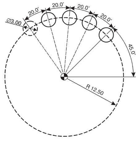
Now you can start creating a simple but very useful parametric program. Quite often there is a need to process several holes located at a certain radius and following through a certain angle (Fig. 10.7). To free the programmer from the tedious redoing of the program in case of changing the radius, angle or number of holes, we will create such a machining program that will allow the operator to enter the values of the radius and angle and perform the drilling operation on a circle with any size.
To drill holes, we will use the G81 canned cycle. The angle at which the holes are located is counted counterclockwise from the X-axis (positive angle).
You need to set:
- the radius of the circle on which the holes are located;
- start angle (the angle at which the first hole is located);
- relative angle (the angle through which the rest of the holes follow);
- the total number of holes.
All this data must be presented in a parametric form, that is, using variables.
Let
#100= radius of circle containing holes;
#101= start angle;
#102= relative angle;
#103= total number of holes.
Rice. 10.7. Let's create a parametric program for processing a part with unknown dimensions
In order to create a parametric program, it is necessary to come up with an algorithm that allows you to change the behavior of the processing program depending on the values of the specified variables. In our case, the basis of the NC is the drilling canned cycle G81. It remains to find a law that describes the coordinates of the centers of the holes for any initial values of the radius, angles, and an arbitrary number of holes.
%
O2000
N10 G21 G90 G80 G54 G40 G49 G00
N20 G17
The first frames of the program will be standard. These are the program number, the security string, and the G17 code for selecting the XY plane.
Since the coordinates of the centers of the holes are specified using the radius and angle, that is, in the polar coordinate system, in block N30 we indicate the code G16.
N40 T1 M6
N45 G43 HI Z100
N50 S1000 M03
#120=0
In block N60 we put the drilling cycle G81 and the coordinates of the center of the first hole. As you remember, in the case of working with polar coordinates, X denotes the radius, and Y specifies the angle. The radius and start angle values are known, they are set by variables #100 (radius) and #101 (starting angle). Some variable #120 with zero value is introduced. This variable is a counter. A little later you will understand the purpose of this variable.
N60 G98 G81 X#100 Y#101 Z-5 R0.5 F50
Variable #103 is responsible for the total number of holes. Since we have already drilled the first hole, we will decrease #103 by 1. Thus, block N70 provides a count of the remaining holes. And block N75 increases the value of variable #120 by 1.
N70 #103=#103-1
N75 #120=#120+1
If the number of holes left to drill is zero, then you should cancel the drilling cycle, turn off the spindle speed and end the program.
N80 IF [#103 EQ 0] GOTO 120
In block N80, the value of variable #103 is compared with zero. If variable #103 is zero, then control is transferred to block N120 at the end of the program. If variable #103 is not equal to zero, then the next block is executed.
N90 #130=#102*#120
N95#110=#101+#130
Block N90 is intended for determining the angular increment. The new variable #110 is the sum of #101 (start angle) and #130 (increment angle). Block N95 calculates the angle of the next hole.
Then a new drilling angle is specified and control is transferred to block N70.
N100Y#110
N110 GOTO 70
With block N70, a closed loop is formed that ensures the calculation of the coordinates of the hole centers and drilling until the value of variable #103 is equal to zero. If the value of #103 becomes zero, then control will be transferred to frame N120.
N120 G80
N125 M05
N130 G15
N140 M30
%
The final blocks of the program are intended to cancel the canned cycle (G80), turn off the spindle speed (M05), turn off the polar coordinate mode (G15) and end the program (M30).
| % O2000 N10 G21 G90 G80 G54 G40 G49 G00 N20 G17 N30 G16 N40 T1 M6 N45 G43 H1 Z100 N50 S1000 M03 #120=0 N60 G98 G81 X#100 Y#101 Z-5 R0.5 F50 N70 #103=#103 -1 N75 #120=#120+1 N80 IF [#103 EQ 0] GOTO 120 N90 #130=#102*#120 N95 #110=#101+#130 N100 Y#110 N110 GOTO 70 N120 G80 N125 M05 N130 G15 N140 M30% |
Any parametric program must be carefully checked before it gets to the machine. Most likely, you will not be able to check such a program with the NC editor and backplot, since it contains variables. The most reliable check in this case is the substitution of values for the input variables and the “unwinding” of the algorithm with specific numbers.
Suppose that the machine operator has received a drawing of a part (Fig. 10.8) for machining holes. He must set the G54 zero point to the center of the part, measure the length of the drill and install it in the spindle. Then enter the MACRO variable area and enter the following numerical values:
| variable number | Meaning |
|---|---|
|
… 100 101 102 103 104 105 … |
… 12.5 45 20 4 0 0 … |
Rice. 10.8. Instead of variables in the drawing, there are specific dimensions and the number of holes is known
To check the created parametric program, it is enough to substitute specific values of the variables and, by “scrolling” the algorithm, get a regular program.
The same program can be written in the usual form:
| % O2000 N10 G21 G90 G80 G54 G40 G49 G00 N20 G17 N30 G16 N40 T1 M6 N45 G43 H1 Z100 N50 S1000 M03 N60 G98 G81 X12.5 Y45 Z-5 R0.5 F50 N100 Y65 N100 Y85 N100 Y105 N120 N120 N140 M30% |
Now let's try to create a macro program that will function similarly to a canned loop. To process the part shown in Fig. 10.8, the machine operator must enter and execute the following command:
G65 P9010 I12.5 A45 B20 H4
In this case, our parametric program (with the new number O9010) must already be in the memory of the control. As a rule, macro programs have numbers from 9000 and higher and are not available for free editing. The G65 command is for non-modal macro call. In this case, the addresses I, A, B, H in the block with G65 transfer their numerical values to certain local variables. To find the correspondence of addresses to local variables, you can use the table. 10.3.
We can tweak the variables in our program by inserting the following lines into the program:
#100=#4
#101=#1
#102=#2
#103=#11
The result is a macro program:
| % O9010 #100=#4 #101=#1 #102=#2 #103=#11 N10 G21 G90 G80 G54 G40 G49 G00 N20 G17 N30 G16 N40 T1 M6 N45 G43 H1 Z100 N50 S1000 M03 #120=0 N60 G98 G81 X#100 Y#101 Z-5 R0.5 F50 N70 #103=#103-1 N75 #120=#120+1 N80 IF [#103 EQ 0] GOTO 120 N90 #130=#102*#120 N95 #110=#101+#130 N100 Y#110 N110 GOTO 70 N120 G80 N125 M05 N130 G15 N140 M30 % |
Although the parametric program we have created is not optimal, however, it clearly demonstrates the wide possibilities of this method for creating effective NC programs and various machine cycles.


How to understand: will the kitten be fluffy?
What kind of light alcohol can be drunk for pregnant women: the consequences of drinking
Why do the legs swell in the ankles and ankles of the feet in pregnant women: causes and methods of treatment
The wedding of Prince Harry and Meghan Markle: scandalous and secret details of the marriage (photo) The future marriage of Prince Harry year NTV
How to close white plums for the winter