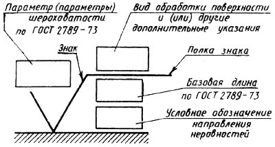
Surface roughness is a set of surface irregularities with relatively small steps, highlighted using the base length.
Conventionally, the boundary between deviations of the surface shape of different orders can be set by the value of the pitch ratio ( SW) to the height of irregularities ( wz):
at – deviations refer to surface roughness;
at ![]() - deviations refer to waviness;
- deviations refer to waviness;
at - deviations refer to deviations of the surface shape.
base length (l ) is the length of the base line used to highlight irregularities that characterize the surface roughness.
Six parameters are accepted as parameters (criteria) for assessing roughness in Russia and in most countries of the world:
altitude parameters
1) Ra- arithmetic mean profile deviation;
2) Rz- height of profile irregularities by ten points;
3) Rmax- the highest height of profile irregularities;
step parameters
4) sm– average step of irregularities;
5) S- average pitch of local protrusions of the profile;
reference parameter
6) tp- relative reference profile length.
When designating the roughness in the drawings, all height parameters are specified as numerical values in micrometers (µm) without specifying a unit, all step parameters are specified as numerical values in millimeters (mm) without specifying a unit, the reference parameter is specified as numerical values in percent (%) and also without specifying a unit . Let's take a look at each of these options.
The arithmetic mean profile deviation is defined as follows:

where n is the number of selected profile points on the base length; yi- profile deviation or distance between the profile point and the midline.
The middle line of the profile is a base line that has the shape of a geometric profile and is parallel to the main direction of the profile along the entire base length, so that, within the base length, the sum of the areas enclosed between this line and the profile are the same on both sides of it, i.e.
F1 + F3 +... Fn-1 = F2 + F4 +...+ Fn (if n- even number).
The middle line of the profile is indicated by the letter " m» (Fig. 5.1).
The height of the profile irregularities at ten points is determined by the formula

where Hi- distances from five points of protrusions to the middle line of the profile; hi- the distance from the five points of the depressions to the middle line of the profile (Fig. 5.1).
Ledge line - a line parallel to the center line and passing through the highest point of the profile within the base length.
Profile valley line - a line parallel to the midline and passing through the lowest point of the profile within the base length.
The average step of irregularities is determined by the formula
![]() ,
,
where n- the number of steps of profile irregularities along the midline (Fig. 5.1); Smi– i-th step of irregularities (segment of the middle line of the profile between the intersection points of adjacent sides of the same name of the profile and the middle line).
The average pitch of local protrusions is determined by the formula
where Si-i-th step of local protrusions of the profile, i.e. midline segment between projections on it highest points neighboring local protrusions of the profile (Fig. 5.1).
The relative reference length of the profile is determined by the formula
where tp– relative reference profile length, %; - reference profile length; ( R - section level value); l - base length of irregularities.
Reference profile length ( h p) is determined by the sum of the lengths of the segments bi, cut off at a given level P in the profile material by a line parallel to the center line within the base length:
Section level value ( R) is determined by the formula
where R- profile section level (distance from the line of profile protrusions to the line intersecting the profile parallel to the middle line of the profile); Rmax- the maximum height of irregularities (Fig. 5.1).
Most machine parts have some surfaces that are smoother, while others are less smooth (rough). The roughness of each surface of the part must correspond to the purpose of this surface. The degree of surface roughness is determined by the height of the irregularities in a given area of the surface. When drawing up sketches of parts from nature to determine the surface roughness, the parts must be measured the height of the irregularities on the surface of a certain length established by GOST.
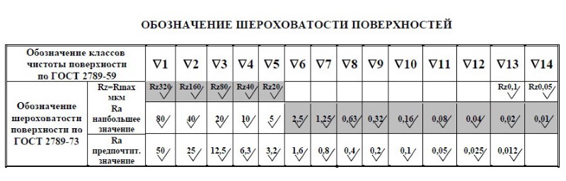
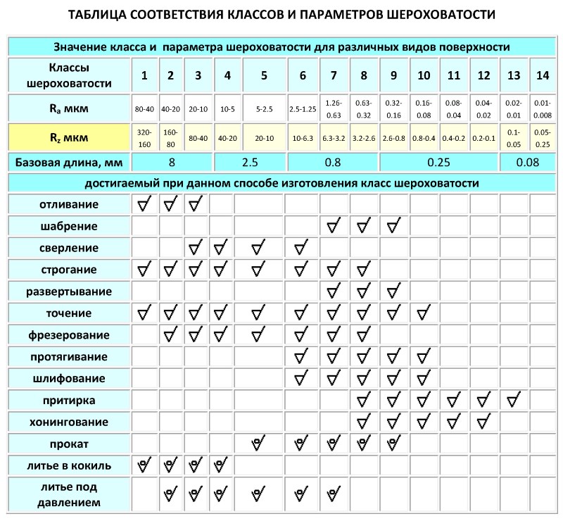
The measurement is carried out with special instruments (microscopes and profilers) or by comparison with samples (standards). 14 classes of surface cleanliness have been established. To designate all classes of surface cleanliness in the drawings, one sign is used - an equilateral triangle, to the right of it the class of cleanliness is indicated. When drawing up sketches from nature and when detailing assembly drawings for an approximate determination of the surface roughness of a part in the case when it is not possible to use accurate measuring instruments, it is necessary to establish the purpose of this surface and, depending on this, determine the surface cleanliness class. An approximate relationship between the purpose of the surface and the class of surface cleanliness is given in table No. 47.
Table 47 Dependence (indicative) between
purpose of the surface and its cleanliness class.
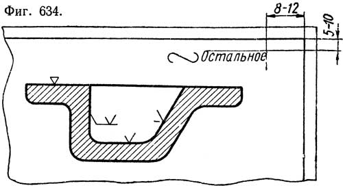
To more accurately indicate the degree of surface roughness, the division of each class of surface cleanliness (starting from the 6th) into three digits, denoted by the letters a, b and c, which are placed after the class number, is used. For example, the designation 7a shows that the height of the irregularities of a given surface should be no more than 6.3 microns; designation 7c - no more than 5.0 microns and designation 7c - no more than 4.0 microns. The indications of the numerical values of the digits are given in GOST 2789-59. To indicate a rough surface, usually not in contact with any other surface and obtained by ordinary casting or forging, the sign ∨ is used, above which the maximum allowable height of irregularities (in microns) is indicated, which is greater than for the first purity class, i.e. more 320 microns (Fig. 634).
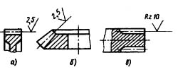
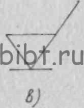
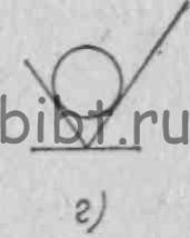
It is allowed to use the sign ~ in the case when it is not required to indicate on the drawings the roughness of individual surface areas, for example, for parts obtained by rolling (calibrated), forging (using smoothers), casting (special), stamping, etc. and not subjected to additional processing. The shape and size of the symbols ∇ , ∨ , ~ used in the designation of surface roughness, the following (Fig. 635):
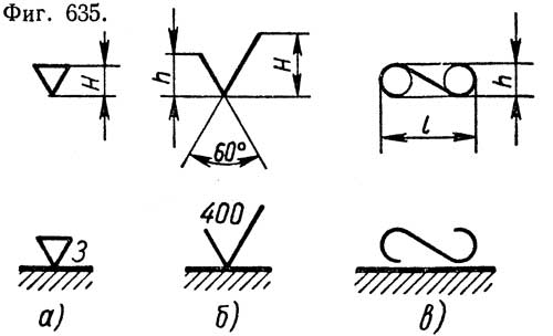
a) the sign ∇ is an equilateral triangle, the height H of which is at least 2.5 mm; the height of the numbers that indicate the class of surface cleanliness should be approximately the same as the height of the triangle (Fig. 635, a);
b) sign ∨ - angle 60°, h = 4 mm, H =1.5 h; the height of the digits of the number indicating the maximum allowable height of irregularities (in microns) should be approximately 2/3 of the height of the sign, and the numbers should not merge with the sign (Fig. 635, b);
in token of ~
consists of two arcs of circles of the same size, connected by an inclined tangent line: h \u003d 2.5 mm; l \u003d Zh (Fig. 635, c).
In the drawing of the part, the designation of surface roughness should be indicated only on the lines of the visible contour (Fig. 636, a). If, due to lack of space or for some other reason, it is inconvenient to indicate the roughness designation on the contour lines, then the designation should be applied to auxiliary (such as extension) lines (Fig. 636, b and c). When designating the roughness of surfaces in several views, one should choose those views and sections on which the dimensions related to these surfaces are given (Fig. 636, d). It is recommended to indicate the surface roughness of bodies of revolution on their generatrix lines (Fig. 636, e). The designation of the roughness of the same surface or part of it should not be repeated several times. With the same roughness of all surfaces of the part, the roughness designation is not applied to its image, but placed in the upper right corner of the drawing, somewhat larger than the usual designation (Fig. 636, e). In the event that most of the surfaces of a given part have the same roughness, the designation of the roughness of these surfaces is placed in the upper right corner of the drawing with the inscription "other", and on the image of the part only the designations of those surfaces that have a different degree of roughness are applied (Fig. 636, g ). To indicate on the image of the same surface of a part of different roughness, solid thin lines are drawn in its various sections, limiting each section, and the corresponding size and designation of the surface roughness are indicated on each section (Fig. 636, h). In the case when the working surfaces of the teeth are not shown in the drawing of the gear wheels of the involute splines (i.e., the tooth profile is not shown), the designation of their roughness is conventionally referred to the initial surface (Fig. 636, and). If it is necessary to indicate the designation of the roughness of the working sides of the thread, then it is applied either by general rules(Fig. 636, k), or conventionally on the thread diameter dimension line (Fig. 636, l).
Before the designation of coatings, the word "Coating" should be added. Notation heat treatment and coatings related to individual places of the part. Should be placed on the shelves of the leader lines, and these places should be outlined with a thickened dash-dotted line (Fig. 637, a).
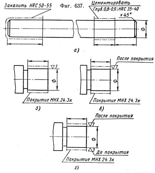
The designation of the coating of the entire part is placed in technical requirements. The sign of the roughness of the surface being coated shows the roughness of this surface before coating (Fig. 637, b). If it is necessary to show the surface roughness after coating, then the inscription "After coating" should be made (Fig. 637, c). It is allowed to indicate simultaneously the roughness of the same surface before coating and after coating (Fig. 637, d). Conventional signs of surface roughness designations should be applied on the side of the line depicting the surface from which this surface can be seen.
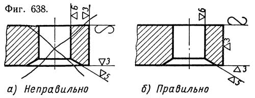
In FIG. 638a shows incorrectly applied signs for the designation of surface roughness, and in FIG. 638, b - correctly applied.
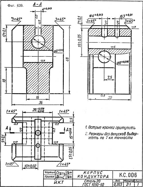
In FIG. 639 shows a working drawing of the body of the conductor for drilling with the designation of surface roughness and maximum dimensional deviations.
Surface roughness- this is a set of surface irregularities with relatively small steps, carved using the base length (Fig. 1)
GOST 2789-73 fully complies with the international standardization recommendation ISO R 468. It establishes a list of parameters and types of roughness directions that should be used when setting requirements and controlling surface roughness, numerical values of parameters and general guidelines.
1. Requirements for surface roughness should be set according to functional purpose surface to provide a given number of products. If this is not necessary, no surface roughness requirements are specified and the surface roughness need not be controlled.
2. Requirements for surface roughness should be set by specifying the roughness parameter (one or more) from the list given in clause 4, the values of the selected parameters (see Tables 3-5) and the base lengths at which the parameters are determined. If the parameters Ra, Rz, Rmax are determined on the base length in accordance with Table. 6 and 7, these base lengths are not specified in the roughness requirements.
In the technical documentation developed before 1975, roughness classes according to GOST 2789-59 were used; for their translation, you can use the data in Table. one.
If necessary, in addition to the surface roughness parameters, requirements are set for the direction of surface irregularities (Table 2), for the method or sequence of methods for obtaining (processing) the surface.
Numbers from the table. 3-5 are used to indicate the largest and smallest allowable values, the boundaries of the allowable range of values and the nominal values of the roughness parameters.
For the nominal numerical values of the roughness parameters, permissible limit deviations should be established. Permissible limit deviations of the average values of the roughness parameters as a percentage of the nominal values should be selected from a range of 10; twenty; 40. Deviations can be unilateral and symmetrical.
3. Requirements for surface roughness do not include requirements for surface defects, so when controlling surface roughness, the influence of surface defects should be excluded. If necessary, requirements for surface defects should be specified separately.
It is allowed to establish requirements for the roughness of individual surface areas (for example, for surface areas enclosed between the pores of a large-pore material, for sections of the cut surface that have significantly different irregularities). The requirements for surface roughness of individual sections of the same surface may be different.
4. Roughness parameters (one or more) are selected from the following nomenclature:
Ka - arithmetic mean profile deviation;
TO% - height of profile irregularities by ten points;
Ktah - the highest profile height;
sm- average step of irregularities;
S is the average step of the local protrusions of the profile;
tp is the relative reference length of the profile, where p is the value of the level of the profile sections.
The Ka parameter is preferred.
5. The numerical values of the roughness parameters (largest, nominal or ranges of values) are selected from the table. 3-5.
6. Relative reference profile length tr: 10; 15; twenty; thirty; 40; fifty; 60; 70; 80; 90%.
I. Roughness classes (GOST 2789-59) and the highest values of roughness parameters corresponding to them (GOST 2789-73)
| Roughness classes |
Roughness parameters, microns |
Base length l, mm | |
| 1 | 320 | 8,0 | |
| 2 | 40 | 160 | |
| 3 | 20 | 80 | |
| 4 | 10 | 40 | 2,5 |
| 5 | 5 | 20 | |
| 6 | 2,5 | 10 | 0,8 |
| 7 | 1,25 | 6,3 | |
| 8 | 0,63 | 3,2 | 0,25 |
| 9 | 0,32 | 1,6 | |
| 10 | 0,16 | 0,8 | |
| 11 | 0,08 | 0,4 | |
| 12 | 0,04 | 0,2 | |
| 13 | 0,02 | 0,1 | 0,08 |
| 14 | 0,01 | 0,05 | |
7. Numerical values of the profile section level R choose from the following:
five; 10; 15; twenty; 25; thirty; 40; fifty; 60; 70; 80; 90% off Mouth.
8. Numerical values of the base length / are selected from the range: 0.01; 0.03; 0.08; 0.25; 0.80; 2.5; 8; 25 mm.
Surface roughness scheme and its elements are shown in Fig. one,
where l- base length; m -
the middle line of the profile; sm- average step of profile irregularities; S is the average step of the local protrusions of the profile; Himax- deviations of the five largest profile maxima; H-imin deviations of the five largest minima of the profile; h imax - distance from the highest points of the five largest maxima to a line parallel to the average and not crossing the profile; h imin - distance from lowest points five highest lows to the same line; Rmax - the highest profile height; y - profile deviations from the line m, tp - relative reference profile length; p- profile section level; bi- - the length of the segments cut off at a given level R.
Fig.1 Scheme of surface roughness and its elements
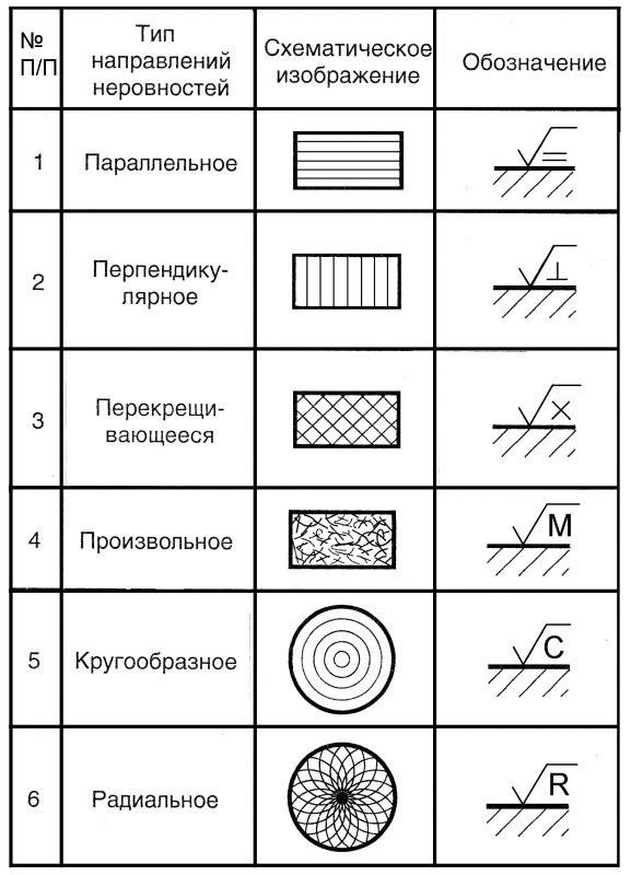
2. Types of directions of irregularities
| Types of roughness directions | Schematic representation | Symbol on the drawing | Explanation |
| Parallel | Parallel to the line that represents the surface in the drawing, to the roughness of which the requirements stop | ||
| Perpendicular | Perpendicular to the line depicting the surface in the drawing, for the roughness of which requirements are established | ||
| criss-cross | Crossing in two directions oblique to the line., Depicting the surface in the drawing, the roughness of which is set requirements | ||
| Arbitrary | Different directions in relation to the line depicting the surface on the drawing, for the roughness of which requirements are established. | ||
| circular | Approximately circular in relation to the center of the surface, the roughness of which is specified | ||
| Radial | Approximately radial to the center of the surface whose roughness is being specified |
| 3. Arithmetic mean profile deviation Ra, µm | ||||
| 100 | 10,0 | 1,00 | 0,100 | 0,010 |
| 80 | 8,0 | 0,80 | 0,080 | 0,008 |
| 63 | 6,3 | 0,63 | 0,063 | - |
| 50 | 5,0 | 0,50 | 0,050 | - |
| 40 | 4,0 | 0,40 | 0,040 | - |
| 32 | 3,2 | 0,32 | 0,032 | - |
| 25 | 2,5 | 0,25 | 0,025 | - |
| 20 | 2,0 | 0,20 | 0,020 | - |
| 16,0 | 1,60 | 0,160 | 0,016 | - |
| 12,5 | 1,25 | 0,125 | 0,012 | - |
| 4. Height of profile irregularities by 10 points Rz and the greatest height of profile irregularities Rmax, micron | |||||
| - | 1000 | 100 | 10,0 | 1,00 | 0,100 |
| - | 800 | 80 | 8,0 | 0,80 | 0,080 |
| - | 630 | 63 | 6,3 | 0,63 | 0,063 |
| - | 500 | 50 | 5,0 | 0,50 | 0,050 |
| - | 400 | 40 | 4,0 | 0,40 | 0,040 |
| - | 320 | 32 | 3,2 | 0,32 | 0,032 |
| - | 250 | 25,0 | 2,5 | 0,25 | 0,025 |
| - | 200 | 20,0 | 2,0 | 0,20 | - |
| 1600 | 160 | 16,0 | 1,60 | 0,160 | - |
| 1250 | 125 | 12,5 | 1,25 | 0,125 | - |
|
Note: Preferred parameter values are underlined |
|||||
| Average step of profile irregularities sm and the average step of local ledges S, mm | ||||
| - | 10,0 | 1,00 | 0,100 | 0,010 |
| - | 8,0 | 0,80 | 0,080 | 0,008 |
| - | 6,3 | 0,63 | 0,063 | 0,006 |
| - | 5,0 | 0,50 | 0,050 | 0,005 |
| - | 4,0 | 0,40 | 0,040 | 0,004 |
| - | 3,2 | 0,32 | 0,032 | 0,003 |
| - | 2,5 | 0,25 | 0,025 | 0,002 |
| - | 2,0 | 0,20 | 0,020 | - |
| - | 1,60 | 0,160 | 0,0160 | - |
| 12,5 | 1,25 | 0,125 | 0,0125 | - |
| Ra and base length / | |
| Ra, µm | l, µm |
| Up to 0.025 | 0,08 |
| Over 0.025 to 0.4 | 0,25 |
| " 0,4 " 3,2 | 0,8 |
| " 3,2 " 12,5 | 2,5 |
| " 12,5 " 100 | 8,0 |
| Parameter value ratio Rz and base length / | |
| Rz=Rmax, micron | l, mm |
| Up to 0.10 | 0,08 |
| St. 0.1 to 1.6 | 0,25 |
| " 1,6 " 12,5 | 0,8 |
| " 12,5 " 50 | 2,5 |
| " 50 " 400 | 8,0 |
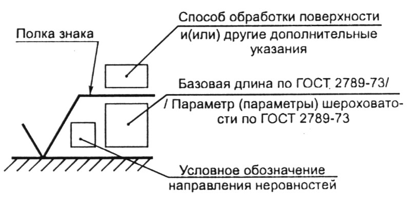
| Fig 2. The structure of the designation of surface roughness
|
Figure 3. Signs of surface roughness
|
Surface roughness designations and rules for applying them on product drawings establishes GOST 2.309-73, which fully complies with ISO 1302-78. Roughness designations are put down on all surfaces of the product made according to the drawing, regardless of the methods of their formation, except for surfaces whose roughness is not due to design requirements.
Structure of the surface roughness designation is shown in Figure 2. If there is only the value of the parameter (parameters) in the roughness designation, the sign without a shelf is used.
In the designation of surface roughness, the type of processing of which is not established by the designer, the sign is used according to Fig. 3, a. In the designation of the surface roughness to be formed by removing a layer of material, such as turning, milling, pickling, etc. use the sign in Fig. 3, b. In the designation of the surface roughness, which should be formed without removing a layer of material, for example, by casting, forging, stamping, rolling, drawing, etc., as well as the surface not machined according to this drawing, use the sign according to fig. 3, in.
The value of the roughness parameter is indicated in the roughness designation:
for parameter Ra - no symbol, such as 0.4;
for other parameters - after the corresponding character, for example Rmax 6,3; sm 0,63; t50 70; S0.032; Rz 32.
(In the example t50 70 indicates the relative reference length of the profile tr = 70 %
at the profile section level R= 50 %).
When specifying the range of values of the surface roughness parameter in the roughness designation, the limits of the parameter values are given, placing them in two lines, for example:
0,8 ;Rz 0,10 ; Rmax 0.80;t50 70
0.4 0.05 0.32 50 etc.
The upper line gives the value of the parameter corresponding to a coarser roughness. When specifying the nominal value of the surface roughness parameter in the designation, this value is given with maximum deviations in accordance with GOST 2789 - 73, for example:
1 + 20 %; Rz 80 -10% ; sm 0,63 + 20% ; t50 70 ± 40% etc.
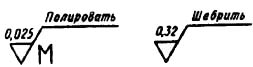
The base length in the designation of surface roughness is not indicated if the requirements for roughness are normalized by indicating the parameters Ra,Rz, and the definition of parameters should be carried out within the base length corresponding to the value of the parameters in Table. 6, 7. The type of surface treatment is indicated in the designation of roughness only in cases where it is the only one applicable to obtain the required surface quality (Fig. 4).
It is allowed to use a simplified designation of surface roughness with an explanation of it in the technical requirements of the drawing according to the example shown in Fig. five.
| Fig 4. Indication of the required type of processing
Fig 6. The order of recording the values of the roughness parameters when specifying two or more parameters
Rice. 8. Designation of the surface roughness of the teeth of the part without specifying their profile
Rice. 10. Designation of the roughness of the contour of the part Rice. 11. Designation of the same rough surface of complex configuration
|
Figure 5. Simplified designation of surface roughness with clarification in the technical requirements
Fig 7. Differentiation of different areas of roughness on the same surface Rice. 9. Designation of the surface roughness of the thread profile
|
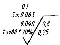
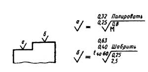
The simplified notation uses the Ö sign and lowercase letters of the Russian alphabet in alphabetical order, without repetition and, as a rule, without gaps. When specifying the nominal value of the roughness parameter, the values of the parameters are recorded from top to bottom in the following order (Fig. 6):
profile irregularity height parameter;
profile roughness step parameter;
relative reference profile length.
If the roughness of the same surface is different in separate areas, then these areas are delimited by a solid thin line with the corresponding dimensions and roughness designations (Fig. 7, but). The boundary line between the sections is not drawn through the shaded zone (Fig. 7, b).
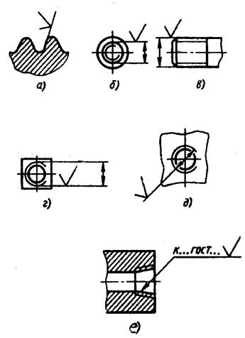
The designation of the roughness of the working surfaces of the teeth of gears, involute splines, etc., if their profile is not shown in the drawing, is conditionally applied to the lines of the dividing surface (Fig. 8, a B C); for globoid worms and wheels associated with it - on the line of the calculated circle.
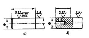
The designation of the surface roughness of the thread profile is applied according to the general rules when depicting the profile (Fig. 9, but) or conditionally on the extension line to indicate the size of the thread (Fig. 9, b, c, e) on the dimension line or on its continuation (Fig. 9, d).
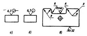
If the roughness of the surfaces forming the contour must be the same, the roughness designation is applied once in accordance with Fig. 10, a, b.
In the designation of the same roughness of surfaces smoothly passing one into another, the sign O is not given (Fig. 10, c).
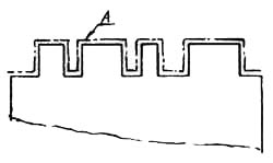
The designation of the same surface roughness of a complex configuration can be given in the technical requirements of the drawing with reference to the letter designation of the surface, for example:
Surface roughness A - Rz10
In this case, the letter designation of the surface is applied on the shelf of the leader line drawn from the thickened dash-dotted line (Fig. 11), which encircles the surface at a distance of 0.8 ... 1 mm from the contour line.
The operational properties of machine parts significantly depend on the quality of the surface. The concept of quality includes:
roughness;
microstructure and physical and mechanical state of the surface layer;
residual stresses.
Rice. fourteen.
The surface roughness is estimated from the irregularities of the profile obtained in the normal section of the surface. It is considered within a limited area - the base length l.
The reading of the profile deviations is determined from the midline m-m - a line that has the shape of a nominal profile and is drawn so that, within the base length, the standard deviation of the measured profile from the midline is minimal (Fig. 14).
For quantitative assessment and standardization of surface roughness, GOST 2789-73 establishes the following indicators:
R max - the highest height of profile irregularities - the distance between the line of protrusions and the line of depressions within the base length;
Ra - arithmetic mean profile deviation - arithmetic mean absolute value of profile deviations from the mean line: 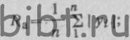
Rz—the height of irregularities at ten points—the sum of the arithmetic mean absolute deviations of the points of the five largest maxima and five largest minima: 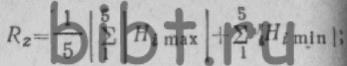
Sm - average pitch of profile irregularities - arithmetic mean of the pitch of profile irregularities within the base length: 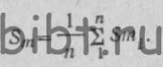
The numerical values of the roughness parameters can be selected within the following limits: the arithmetic mean deviation of the Ra profile is from 0.008 to 1000 µm; the height of the profile irregularities, the maximum height of the irregularities H max and the average step of the irregularities along the vertices S - from 0.002 to 12.5 microns.
Rice. 15. Roughness symbols: 1 - roughness parameter, 2 - sign, 3 - type of surface treatment or other additional indications, 4 - sign shelf, 5 - base length
Surface roughness designations are established by GOST 2.309-73, which is part of the ESKD system. A sign indicating the roughness, as well as the location of the value of the parameter (or parameters) and data containing Additional requirements are shown in fig. 15, a.
If the designation contains only the value of the parameter, then the sign does not have a shelf.
If the type of surface treatment is not set by the designer, then the sign of surface roughness has the form shown in Fig. 15, b.
The sign in fig. 15, c denotes the surface roughness to be formed by cutting or other type of processing with the removal of a layer of material.
The sign in fig. 15, d - surface roughness formed without removing a layer of material (casting, forging, rolling, etc.) and not machined according to the drawing.
Roughness is indicated in the designation:
for Ra parameters - without a symbol, for example 0.32,
for parameters Rz, R max, etc. - after the corresponding symbol, for example, Rz 40, R max 80.
If the drawing shows a product, part or all of the machined surfaces of which must have the same roughness, then the designation of the same roughness and the sign shown in Fig. 15b.
This means that all surfaces that do not have a roughness designation, or the sign shown in Fig. 15, d, should be made with the same roughness.
Surface roughness achieved by machining on lathes are given in table. nine.
Table 9 Surface roughness achieved when machining on lathes
| Processing method |
Surface roughness (according to GOST 2789-73) |
||||||
| Rz 160 | Rz80 | Rz40 | Rz 20 | 2,5 | 1,25 | 0,63 | |
| Turning and boring: | |||||||
| draft | X | X | X | ||||
| finishing | X | X | X | ||||
| finishing | X | X | X | ||||
| drilling | X | X | X | ||||
| Countersinking | X | X | X | ||||
| Deployment | X | X | |||||
Surface roughness is an indicator that indicates a certain amount of data characterizing the state of surface irregularities measured in ultra-small segments at a basic length value. The set of indicators indicating the possible orientation of the directions of surface irregularities with certain values and their characteristics is specified in normative documents GOST 2789-73, GOST 25142-82, GOST 2.309-73. The totality of the requirements specified in the regulatory documents applies to products manufactured using various materials, technologies and processing methods, with the exception of existing defects.
The high quality of processing of parts can significantly reduce the wear of surfaces, the occurrence of corrosion centers, thereby increasing the accuracy of assembling mechanisms and their reliability during long-term operation.
Basic designations
The roughness of the surface under study is measured over small areas, and therefore the base lines are chosen taking into account the parameter of reducing the influence of the undulating state of the surface on the change in altitude parameters.
Irregularities on most surfaces occur due to the resulting deformations of the upper layer of the material during processing using various technologies. The outlines of the profile are obtained during the examination using a diamond needle, and the imprint is fixed on the profilogram. The main parameters characterizing the surface roughness have a certain letter designation used in the documentation, drawings and obtained during measurements of parts (Rz, Ra, Rmax, Sm, Si, Tp).
To measure surface roughness, several defining parameters are used:
The step parameters Sm and Si and the reference length of the investigated profile tp are also used. These parameters are indicated if it is necessary to take into account the operating conditions of the parts. In most cases, the universal indicator Ra is used for measurements, which gives the most complete description taking into account all points of the profile. The value of the average height Rz is used when there are difficulties associated with the determination of Ra using instruments. Similar characteristics affect the resistance and vibration resistance, as well as the electrical conductivity of materials.
The values of the definitions of Ra and Rz are indicated in special tables and, if necessary, can be used when carrying out the necessary calculations. Usually the determinant Ra is denoted without a numeric symbol, other indicators have the required symbol. According to the current regulations (GOST), there is a scale in which the values of the surface roughness of various parts are given, with a detailed breakdown into 14 special classes.
There is a direct relationship that determines the characteristics of the surface to be treated, the higher the class index, the less important is the height of the measured surface and better quality processing.
Control methods
Two methods are used to control surface roughness:
- qualitative;
- quantitative.
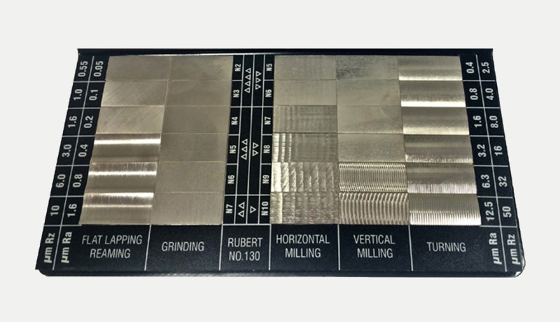
When conducting quality control, a comparative analysis of the surface of the working test and standard samples is carried out by visual inspection and by touch. For the study, special sets of surface samples are produced with routine processing in accordance with GOST 9378-75. Each sample is marked with the indication of the Ra index and the method of influence on the surface layer of the material (grinding, turning, milling, etc.). Using visual inspection, it is possible to accurately characterize the surface layer with the characteristics of Ra=0.6-0.8 µm and higher.
Quantitative control of the surface is carried out using devices operating using different technologies:
- profilometer;
- profiler;
- double microscope.
Surface classification
When determining the characteristics of the surface layer of the material, it is necessary to classify:
Regulatory data is also contained in GOST 2.309-73 according to which designations are applied to the drawings and contain surface characteristics according to established rules and are mandatory for all industrial enterprises. It should also be borne in mind that the signs and their shape applied to the drawings must have a fixed size indicating the numerical value of the surface roughness. The height of the signs is regulated, the type of processing is indicated.
The sign has a special code, which is deciphered as follows:
- the first character characterizes the type of processing of the material under study (turning, drilling, milling, etc.);
- the second character - indicates that the surface layer of the material was not processed, but was formed by forging, casting, rolling;
- the third sign indicates that the type of possible processing is not regulated, but must correspond to Ra or Rz.
In the absence of a sign in the drawing, the surface layer is not subjected to special treatment.
In production, two types of impact on the top layer are used:
- by partially removing the top layer of the workpiece;
- without removing the top layer of the part.
When removing the top layer of material, a special tool is mainly used to perform certain actions - drilling, milling, grinding, turning, etc. During processing, the upper layer of the material is violated with the formation of residual traces from the tool used.
When processing is applied without removing the upper layer of the material - stamping, rolling, casting, the structural layers are shifted and deformed with the forced creation of a "smooth-fibrous" structure.
When designing and manufacturing parts, the parameters of irregularities are set by the designer, based on the technical specifications that determine the characteristics of the product, depending on the requirements for the manufactured mechanism, the technology used in production and the degree of processing.
Surface texture marking
When applying designations in the working documentation, drawings, special signs are used to characterize the material, which are regulated by the GOST 2.309-73 standard.
Basic Rules Used to Indicate Surface Roughness in Drawings
The basic rules to be used when making a drawing:
Given the structure of the material, the designer has the opportunity to specify the necessary parameters for the quality of the surfaces. Moreover, the characteristics can be indicated by several parameters with the installation of the maximum and minimum values with possible tolerances.
Special conditions
In the mass production of certain parts, the given shape or their conjugation is sometimes violated. Such violations increase the permissible wear of parts, and are limited by special tolerances, which are specified in GOST 2.308. Each type of tolerance used has 16 defining degrees of accuracy, which are negotiated for parts of different configurations, taking into account the material used. It should also be taken into account that the size and configuration tolerances used for parts having a cylindrical shape are taken taking into account the diameter of the parts, and flat parts, taking into account the thickness, and the maximum error should not exceed the tolerance indicator.
The correct use of the technique for determining the surface roughness indicators allows to achieve a higher accuracy of processing and the size of parts, while observing the parameters specified in the regulatory documents, which make it possible to significantly improve the quality of the finished product.
If you find an error, please highlight a piece of text and click Ctrl+Enter.


Living and dead water: myth or reality, what is the power of living and dead water?
Craniosynostosis, or premature fusion of the bones of the skull Frontal crest in a child
Beautiful hair How to achieve hair density at home: useful tips
Why mosquitoes bite some people, but not others
How to achieve beautiful hair