For a long time I planned to assemble some kind of adaptation for normal drilling of seals. I'm tired of dealing with the result of my crooked hands after drilling double-sided boards: skewed, disheveled copper, torn nickels, or even worse, broken drills. All this is the result of manual drilling. Another big disadvantage is that simple metal drills do not last long when drilling textolite. Some disorders in general. All this can be solved using carbide drills and most importantly, using a drilling machine.
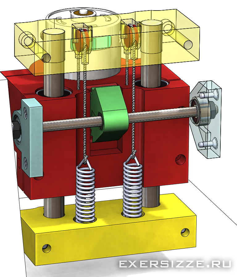
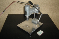
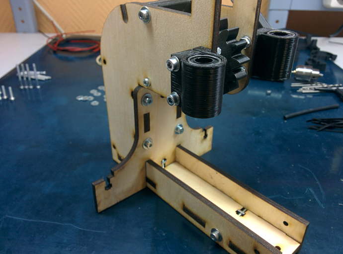
A general view of what should turn out in the picture below. The base is planned to be made of chipboard, it should turn out to be quite rigid and, most importantly, an inexpensive design.
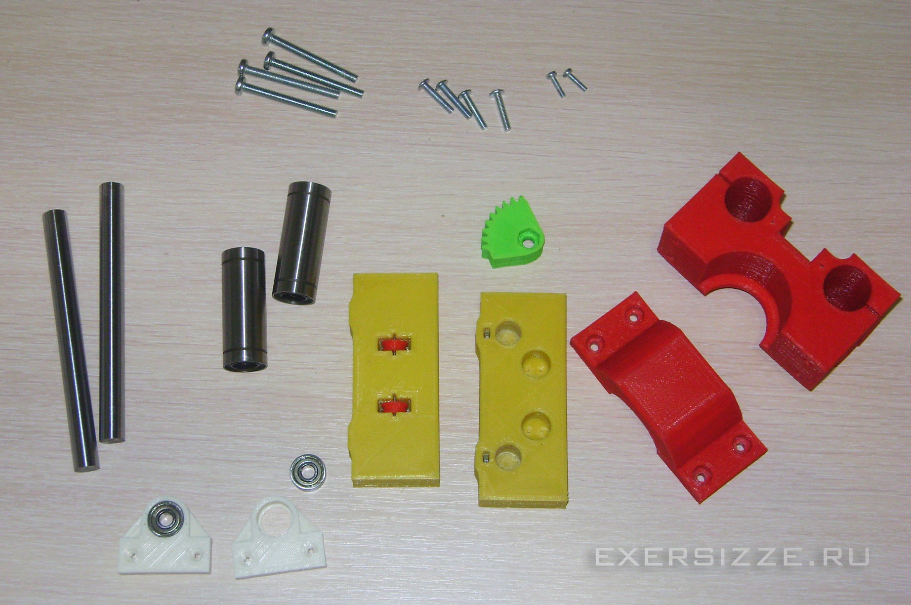
Main parts are 3D printed, total 9 printed parts. I took two pieces of polished shafts with a diameter of 12 mm as guides. and 130 mm long. I bought two elongated linear bearings LM12LUU for them. You will also need an M6 hairpin 145 mm long. It will connect the handle to the feed gear (green in the photo). Well, some standard fasteners.
The gear is fixed on the stud with nuts on both sides, for this it has recesses for the nuts. And so that they do not rotate, they are additionally pressed on both sides with self-locking nuts with a Teflon insert:
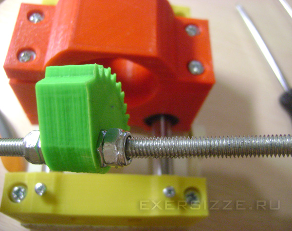
The stud will spin in the support blocks into which bearings of size 606 are inserted

Such bearings can be found in stores selling spare parts for hand power tools, go as a repair kit to different drills and screwdrivers.
Two rollers are inserted into the upper support block that will hold the guides. The axis for them is a steel wire with a diameter of 1.5 mm and a length of 10 mm. You can take, for example, thin carnations and chop rods from them, which I did
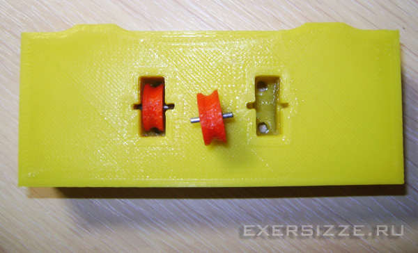
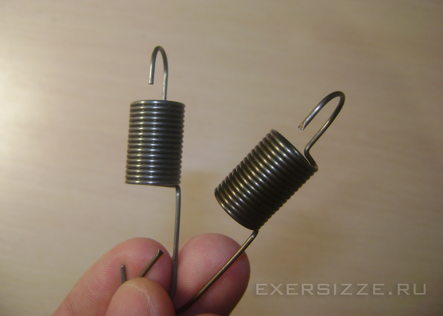
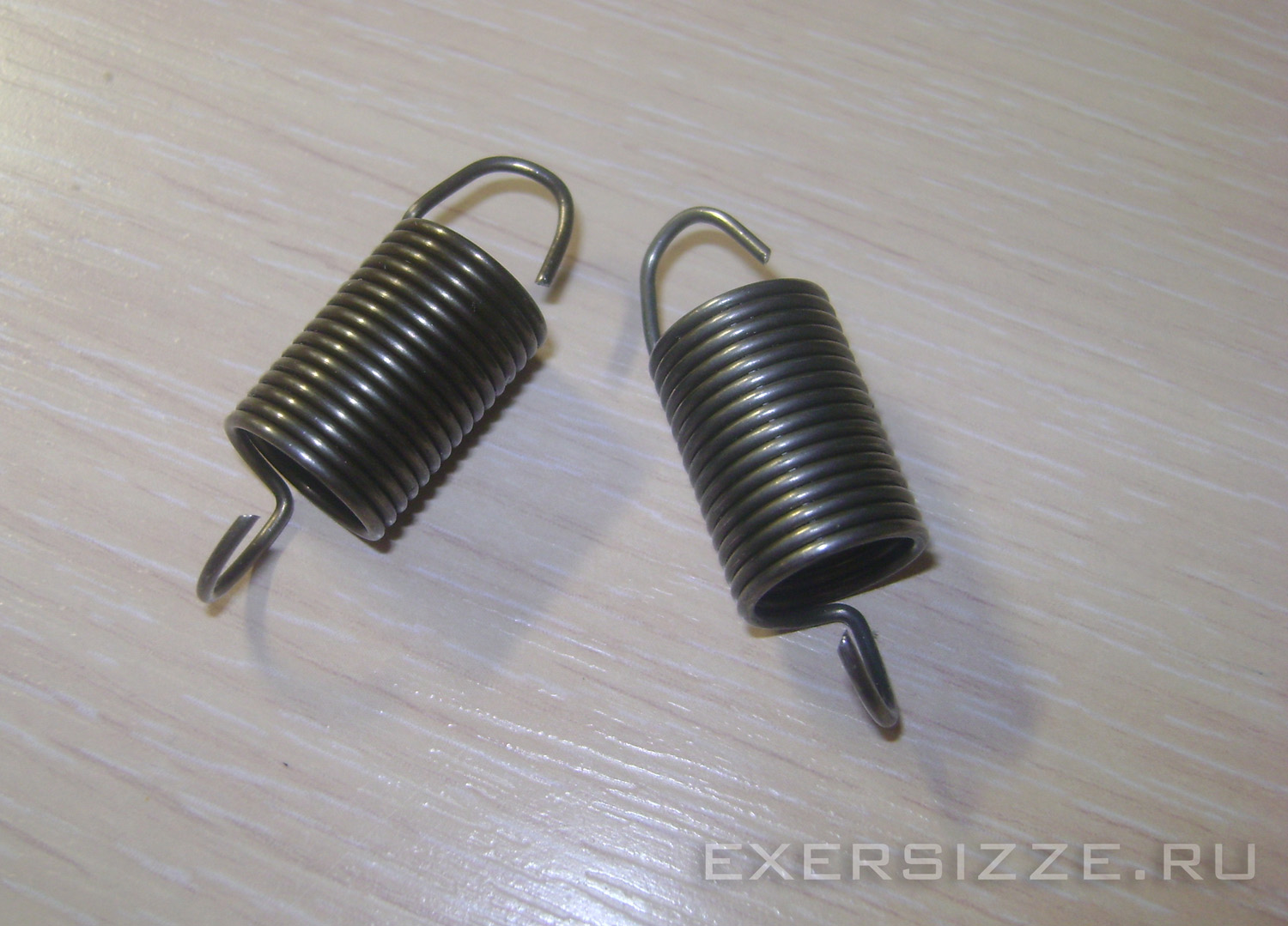
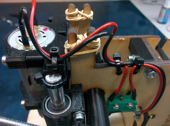
A cable will pass through these rollers, which will pull the carriage up. The other end of the cable is attached to the spring. According to guesses, the total mass of the carriage + spindle + 2xLM12LUU will be about 750 grams, so the springs must be selected such that they can pull such a weight. External diameter springs no more than 12 mm, otherwise they will rub against the walls.
I found suitable springs in an auto parts store, these are on the intake air manifold of a VAZ classic carburetor. After a little manipulation of the pliers, I made them shorter
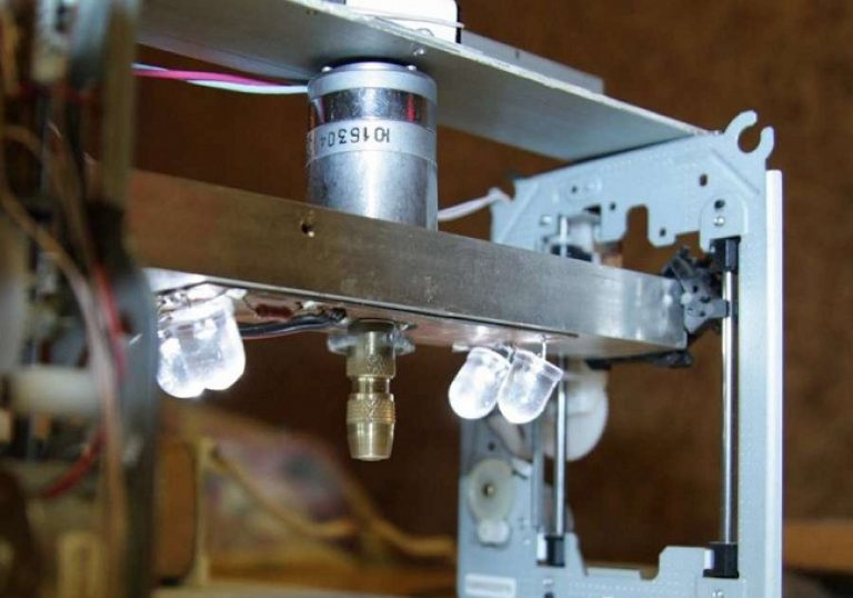
To understand the general design idea, look at the picture below. View of the mechanics of the machine without rear walls
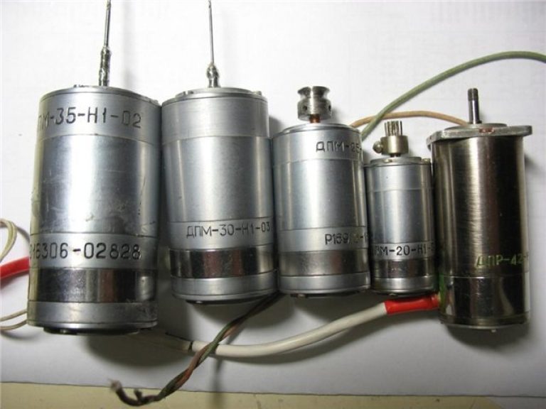
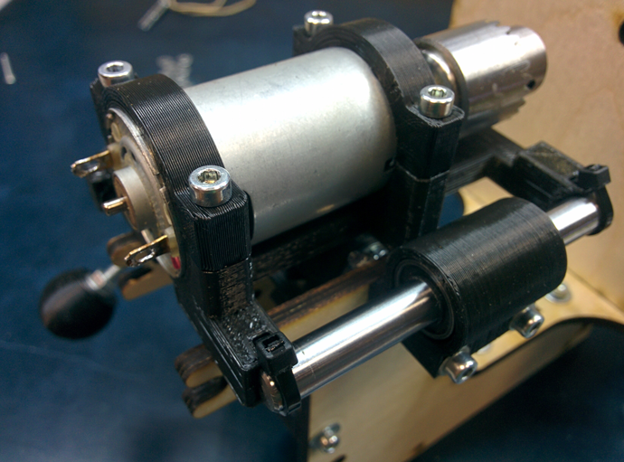
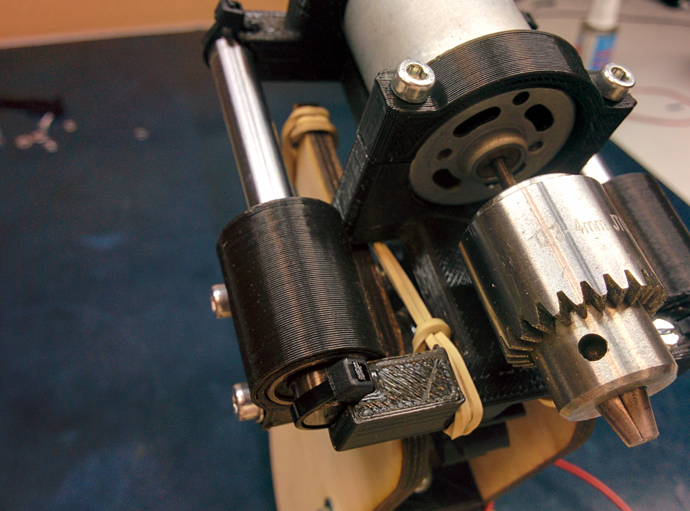
For drilling, I chose such an engine, in the search engine and on all kinds of aliexpress it is like motor R775 supply voltage 12 volts, revolutions 13000-15000 per minute, shaft diameter 5 mm.

And I took for him such a cool ER11 collet for a drill shank diameter of 3.175 mm (1/8 inch)
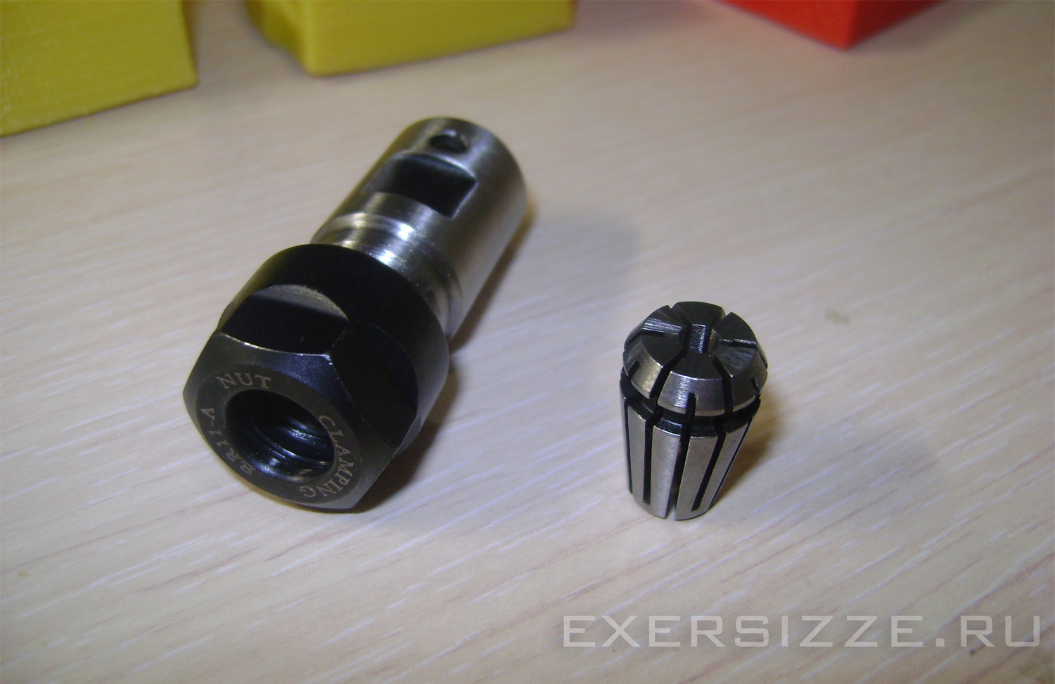
The hole in the collet holder is two hundred parts smaller than the diameter of the motor shaft, so it must be preheated to fit it gas burner or a powerful soldering iron. Or you can just work with a needle file, making the hole freer. But then there is a possibility that alignment will be violated.
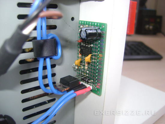
The engine turned out to be very powerful and, when turned on, took my power supply into protection. Therefore, for soft start engine assembled a schematic on a 555 timer:

Capacitor C1 is timing, the higher its capacity, the smoother the engine accelerates. As a result, I settled on a capacitance of 330 microfarads, the time to reach full speed is about 5 seconds.
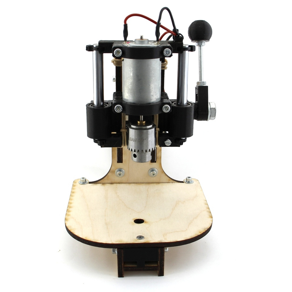
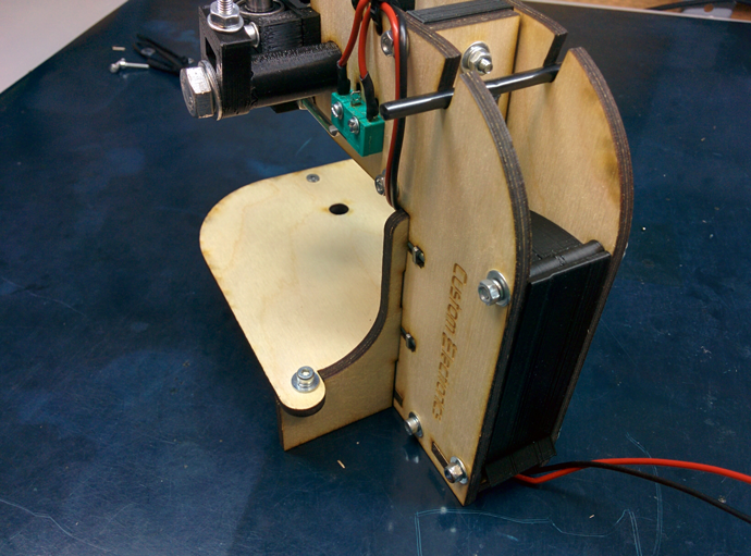
General view of the machine. As you can see, I did not install two rear walls, planned as stiffeners, and without them it turned out very strong. Both front walls are tightened together with self-tapping screws, and from below they are drawn to the base with confirmations.
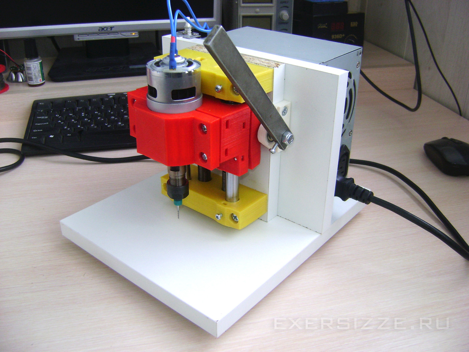

It is planned to drill textolite with such carbide drills. The smallest diameter in the set is only 0.3 mm!
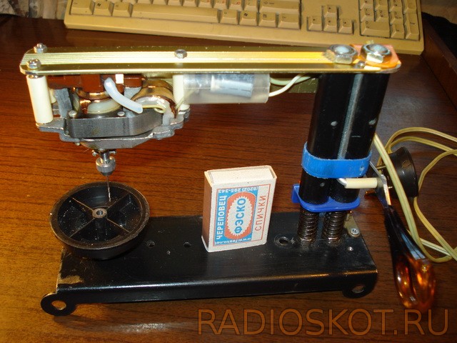
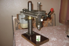
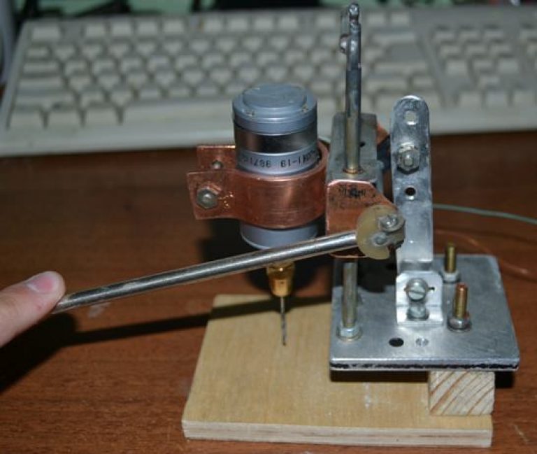
The first version of a desktop machine for drilling circuit boards was made three years ago. He did it purposefully, specifically for drilling boards (not intended for another) and exclusively from improvised materials, he did it on " hastily»as a temporary fixture, spent a day off making it. And he took it and "got accustomed" - it turned out to be unusually convenient in work.
The diameter of drills that can be used is from 0.5 to 1 mm inclusive. Sprint start, finish without inertia. He summed up the board, pressed it - the hole was ready, released it - the drill returned to its original position by itself. For all 2-3 seconds. Six months later, once the thing came "to the court", I spent another evening and gave it a more appropriate and acceptable look.

The device and the principle of operation, as you can see, remained the same. Two more years passed, but I was not going to do something more solid, although the components for this were selected. From good, good is not sought. But he allowed himself the modernization.
There have been significant changes:
- lowering occurs by pressing the handle
- the electric motor is switched on when lowering at the moment the button is pressed against the stop
- a table for drilling on threads and can be raised - lowered to adjust the distance from the surface of the board to be drilled to the "point" of switching on the electric motor
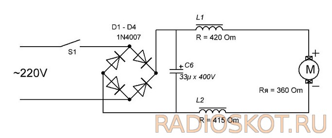
- electric motor powered by direct current
WITH tank for drilling boards - wiring diagram
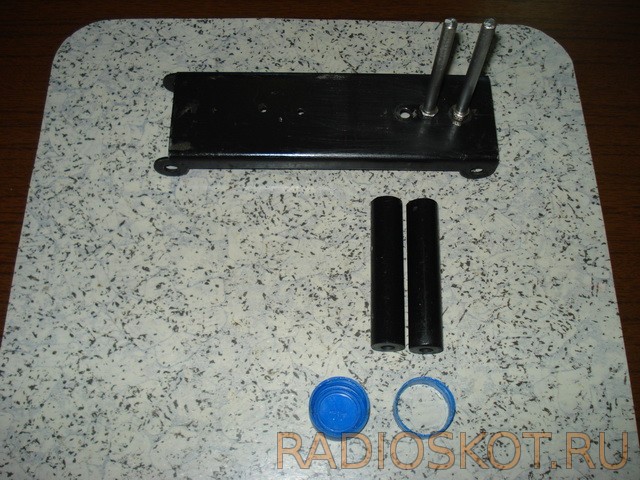
The basis of the entire frame and guides.
![]()
bushings, their inner diameter only one - two tenths of a millimeter more than the diameter of the guides, the material is ebonite (dielectric), not chosen by chance, this is a kind of "decoupling" from electric current. What the belt is made of, which later fixes the traction, is not difficult to guess.
The button - switch is fixed on a plastic corner with 2 screws and nuts, the corner itself is connected to the bushings with glue.
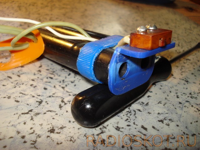
There is an M2 threaded hole in the motor shaft, it was not difficult to fit the collet. And the felt seals (on both sides of the shaft) waited for the oil.

As a "bearing" element, to which the engine is attached and which, in turn, is attached to the bushings, a furniture corner was chosen (light, durable and easy to process). Diode bridge and capacitor in a protective casing.

The stop consists of a spring, on one side of which the rubber stop itself is glued, on the other, a nut is soldered, which is screwed onto a screw that is mounted on a thread in the hole in the bed.

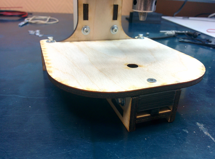
The drilling table is mounted on a screw (its additional function is described above).

And finally, how it all works:
Video of the drilling process
For those who liked it: everything from which this machine was assembled for, previously lay in cans, boxes and just corners. I think the hint is more than obvious. I wish your drills never get dull, Babay.
Discuss the article MACHINE FOR DRILLING PRINTED BOARDS
Since the invention of the machine tool, the production of various mechanisms and parts has advanced significantly. Now they are the real assistants of a person engaged in the processing of metals, plastics, wood and other materials.
These devices allow you to perform quite specific work at a higher quality level.
This type of equipment can also be attributed to a home-made drilling machine for printed circuit boards used in radio electronics and related fields.

Machines for printed circuit boards
Printed circuit boards are the basis of all microcircuits. It is designed for mechanical and electrical connection of different electronic components.
Such boards are produced from a dielectric material, on which all elements of microelectronics are subsequently installed.
Transistors, thyristors and other microelectronics are installed on the boards, i.e. a large number of miniature details that are difficult to see with the naked eye.
Additional elements are added to the simplest boards by screwing them with subsequent soldering. Naturally, in order to screw the elements, it is necessary to drill holes in the board. It is necessary to make such holes with jewelry precision. A discrepancy of even a couple of hundred microns can be very noticeable or lead to product defects if you are going to place a large number of electronic components on the board.
Electronics hobbyists are often involved in the manufacture of printed circuit boards, in which it is necessary to drill a large number of holes of small diameter. Drilling small holes with a diameter of 0.5-1.0 mm using a classic bench drill, drill or screwdriver is not a very convenient task, during which it is easy to break the drill. As a result, it is advisable to drill micro-holes in printed circuit boards using a specialized mini drilling machine, using carbide drills with a diameter of 0.7-0.8 mm.
The use of a mini drilling machine greatly simplifies the work, making it almost mechanical, thereby increasing labor productivity. At the same time, the design is not particularly difficult, for these reasons, many prefer to assemble them with their own hands.
With such a home-made mini drilling machine, you can drill both printed circuit boards and any other workpieces, however, due to the design of the machine, there are restrictions on the depth of the hole.
Design
At first glance, the scheme seems complicated, however, it is not. In fact, the mini machine does not differ much from the classic one, it is smaller in size with some nuances in the design layout.
Since this equipment is not large, it should be considered as a desktop.
A home-made version of the equipment is usually slightly larger than a purchased one, due to the fact that when assembling with your own hands, it is not always possible to optimize the design by picking up small-sized components. But even in this case, a home-made machine will have small dimensions and a weight of no more than 5 kg.
Assembly video
Drilling machine elements
To assemble a mini device with your own hands, you will need the following:
- Bed;
- Transitional stabilizing frame;
- Plank for movement;
- shock absorber;
- Height adjustment handle;
- Engine mount;
- Engine;
- collet (or chuck);
- Adapters.
It is worth noting that we are describing a homemade mini drilling machine, assembled from improvised do-it-yourself tools. The factory design is distinguished by the use of specialized units that are almost impossible to make with your own hands.
The basis of a mini drilling unit, like any other, is a bed. It performs the function of the base on which all nodes will be held. The bed can be an improvised device, for example: the skeleton of a microscope; stand for holding linear measurements digital indicator.
And you can make it yourself, for example, a light wooden frame - by connecting the boards with self-tapping screws, or a heavy and stable one - by welding steel profile To metal sheet. It is better when the weight of the frame is higher than the main weight of the other nodes, this allows you to increase the stability of the unit and reduces its vibration during operation.
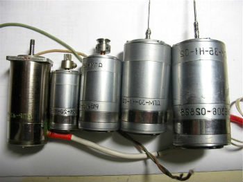
Electric motors from: cassette recorders, printers, disk drives and other office equipment can serve as an engine for. A chuck or collet is selected as a mount for drills. However, the chuck is more versatile, while the collet provides for the installation of drills of only certain sizes.
Another interesting scheme based on spare parts from a CD-ROM and a hair dryer with automatic adjustment of the engine speed depending on the load.
Homemade bed
When making a steel bed with your own hands, you can screw the legs under it to fix its position.
The stabilizing frame can be made, for example, from a rail or a corner, it is better to use steel.
You can choose any type of bar for moving, the most convenient, while it is better to combine it with a shock absorber. In some cases, the shock absorber may itself be such a bar. The function of these parts is to vertically move the equipment during operation.
You can make a shock absorber yourself or remove sliding rails from office furniture, or purchase it in a store.
The height adjustment knob is mounted on the body, stabilizing rail or shock absorber.
The engine mount is mounted to a stabilizing frame, for example, it can be a simple wooden block. It is needed to bring the engine to the desired distance and securely fix it.
Then the engine is installed directly on the mount.
A chuck or collets are directly attached to the engine, to which adapters are attached, used to install drills. Adapters are selected individually, depending on the motor shaft, its power, type of drills, etc.
In conclusion, we can say that the assembled mini drilling machine can be constantly refined during operation. For example, you can stick an LED strip on the chuck to illuminate the drilled samples.
With the invention of machine tools, mankind has seriously advanced in the production of various kinds of parts and mechanisms. Machine tools have become a real help for anyone who intends to process metals, wood and any other materials.
After all, these devices are originally intended to perform rather specific work, which you will not be able to perform in a different way.
Such equipment also includes a drilling machine for printed circuit boards, which is used in electromechanics and related production areas.
1 General information
Any machine is a special device that is assembled from several components. The task of this device is to give a person the opportunity to process a particular tool with great accuracy. That is, practically exclude manual labor from the process.
This is absolutely necessary in work where accuracy is needed. If at the same time a part made of metal or any precise material is used, then you simply cannot do without using a machine.
The machine consists of a frame, adapters, installation under the engine and several other mechanisms. All of them are assembled into a single structure, which is rigidly fixed in one or more positions.
Standard and cheapest machines or mini-machines if we are talking about equipment that designed for processing miniature parts, can only move in one axis. That is, the movement of the working drill is performed from top to bottom. This is the basic function of the machine, without which it cannot be called a machine.
More advanced models can be fine-tuned to a specific coordinate that is displayed on the table. It can already be even semi-automatic or automatic models.
As you understand, it is precisely the clear fixation on a solid frame and the ability to practically eliminate the human factor directly in the performance of drilling work - this is the main plus of the machines.
1.1 Features of PCB machines
Machines for printed circuit boards - this is one of the varieties of such equipment. Here are just such units, as a rule, are mini-samples. And this is quite obvious, because it is necessary to work on them with printed circuit boards.
For those who are not familiar with electrical engineering, let's be clear that printed circuit boards are essentially the basis for any microcircuit or electronic mini-circuit. Almost every device in its design has at least one printed circuit board. This is especially true for appliances that run on electricity.
To form uniform standards in electrical engineering and create a stable foundation, printed circuit boards were introduced. They are made from a dielectric, on which various parts and connections are screwed or soldered.
The board can contain both a small transistor and a lead to it from the battery, as well as a huge number of parts, so miniature that an unprepared person will not even consider them(we are talking about computer hardware).
Of course, in this situation, it is worth noting the huge number of printed circuit boards that differ in their design, material used, etc. But we note that all of them are a kind of one element, which acts as the basis for microcircuits.
The simplest boards are equipped with additional elements due to their screwing and subsequent soldering. As you understand, for screwing parts, you need to make holes in the board.
And it is necessary to do them with filigree precision. A discrepancy of even half a millimeter can be, if not fatal, then very noticeable. Especially if you are going to fill the board completely.
What is the fact that drills for a mini-machine on printed circuit boards in their diameter can start from samples of 0.2-0.4 mm. And this is if we talk about cheap machines. More advanced hardware to build complex circuits will use even smaller tools.
As you can imagine, handling such parts by hand is not an easy task. Even if you manage to make a couple of holes in the right place and the right thickness, this process will take too long, and the result can be spoiled by a single mistake.
Using the same machine for printed circuit boards, work is greatly simplified and becomes almost mechanical. As well as increasing its performance. And the design of such equipment does not differ in complexity, so you can create it yourself.
2 Machine design
The design of mini PCB processing machine has quite a simple circuit. In fact, this machine is not much different from standard drilling models, only it is much smaller and has several nuances. We almost always consider a desktop mini drilling unit, as it will have dimensions that rarely exceed the 30 cm mark.
If we consider a home-made sample, then it may be a little larger, but only due to the fact that the person who assembled it with his own hands simply could not optimize the design properly. This happens if there are simply no suitable parts at hand.
In any case, the machine, even if it is assembled by hand, will have small dimensions and weigh up to 5 kilograms.
Let us now describe directly the design of the machine, as well as the parts from which it must be made. The following are used as the main components when assembling a mini-device for drilling boards:
- bed;
- transitional stabilizing frame;
- bar for moving;
- shock absorber;
- a handle for manipulating height;
- engine mount;
- engine;
- power unit;
- collets and adapters.
2.1 Analysis of specific details
Let us now turn to the specific details that have already been mentioned above, and also give recommendations on their selection.
To begin with, we note that we are now describing a home-made machine, which, in fact, can be assembled from improvised means. The design of factory samples differs from that described by us only in the use of specialized materials and details that are almost impossible to create at home. Will have to buy.
A home-made mini-machine begins, like any other machine, from the bed. The bed acts as a base, the entire structure rests on it, and a supporting part is mounted on it, on which the processed board is attached.
It is desirable to make the bed from a heavy metal frame. Its weight should be greater than the weight of the rest of the structure. Moreover, the discrepancy can be quite impressive. The only way you will achieve the stability of the unit during operation. This is especially true for models that are assembled by hand.
And do not be deceived when you see the mini prefix. A mini-machine is the same machine, and it still requires high-quality stabilization. Legs or something similar are often screwed under the bed to further fix its position.
The stabilizing frame is the mount for the entire mechanism. It is made from a rail, a corner or something like that. It is preferable to use detail. The travel bar can be of a wide variety of designs and is often combined with a shock absorber. Sometimes, the shock absorber itself is a bar for movement.
These two parts perform the functions of vertical displacement of the machine during operation. Thanks to them, the machine can be operated quickly and effortlessly.
There are a lot of options for making such details. Starting from home-made or removed from office furniture sliding rails on a spring, to professional oil-type shock absorbers.
The handle for manipulation is attached directly to the machine body, shock absorber or stabilizing rail. With its help, you can apply pressure on the structure, lowering and raising it at will.
A bar for the engine is already attached to the stabilizing frame. It can even be an ordinary wooden block. Its task is to bring the engine to the desired distance and its secure fixation.
The engine is mounted on a mount. As an engine, you can also use a huge number of parts. Starting from a drill, and ending with engines that are removed from printers, disk drives and other office equipment.
![]()
Collets and adapters are attached to the engine, which will be the basis for attaching the drill. Here you can only give general recommendations, as adapters are always selected individually. Their choice will be influenced by the motor shaft, its power, the type of drill used, etc.
The power supply for the mini-machine is selected so that it can provide the engine with the required voltage in sufficient quantities.
2.2 Machine assembly technology
Now let's turn to the general algorithm for assembling the unit for drilling printed circuit boards with our own hands.
Stages of work:
- We mount the frame, attach the legs to it.
- We install the frame of the holder of the main structure on the frame.
- We fasten the movement mechanism and shock absorber to the frame.
- We mount the mount for the engine, as a rule, it is fixed on the movement frame.
- Install the handle on the engine mount.
- We install the engine and adjust its position.
- We fasten the collet and adapters to it.
- We mount the power supply, connect it to the engine and the network.
- We select and fix the drill.
- Testing the mechanism.
All connections and their type you can choose at your discretion. However, it is recommended to use bolts and nuts in order to be able to disassemble the structure at the right time, replace its components or improve the entire scheme of the machine.
2.3 Homemade machine for drilling printed circuit boards (video)
Hello! There are a lot of people on this resource who are engaged in electronics and make printed circuit boards on their own. And each of them will say that PCB drilling is a pain. Hundreds of small holes have to be drilled, and everyone independently solves this problem for himself.
In this article, I want to present to your attention an open project of a drilling machine that everyone can assemble on their own and he does not need to look for CD drives or microscope stage tables for this.
Design description
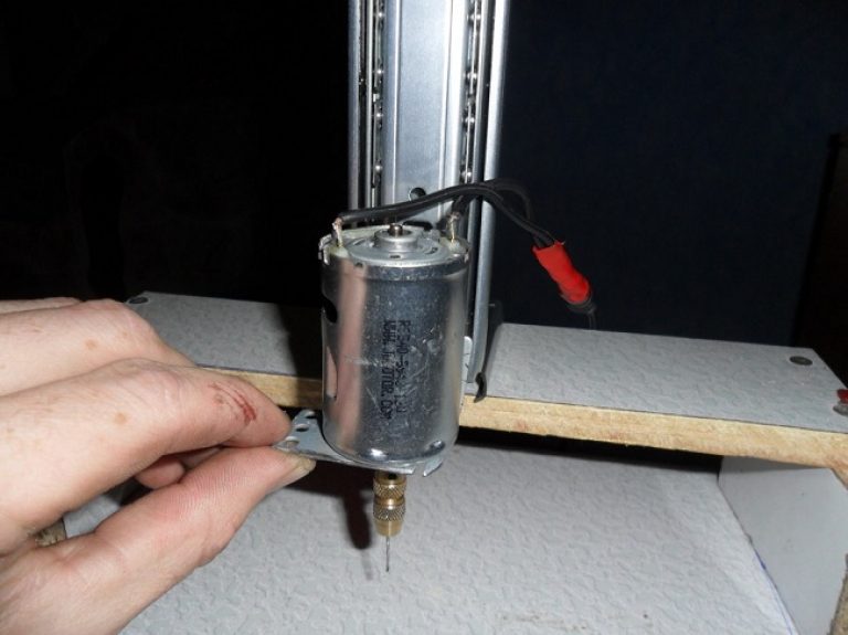
The design is based on a fairly powerful 12 volt motor from China. Complete with the engine, they also sell a cartridge, a key and a dozen drills of different diameters. Most hams just buy these motors and drill the boards with the tool in hand.
For the linear movement of the motor, I decided to use polished shafts with a diameter of 8mm and linear bearings. This makes it possible to minimize backlash in the most critical place. These shafts can be found in old printers or purchased. Linear bearings are also widely available and widely used in 3D printers.
The base frame is made of 5mm plywood. I chose plywood because it is very cheap. Both the material and the cutting itself. On the other hand, nothing prevents (if possible) from simply cutting out all the same parts from steel or plexiglass. Some small details of complex shape are printed on a 3D printer.
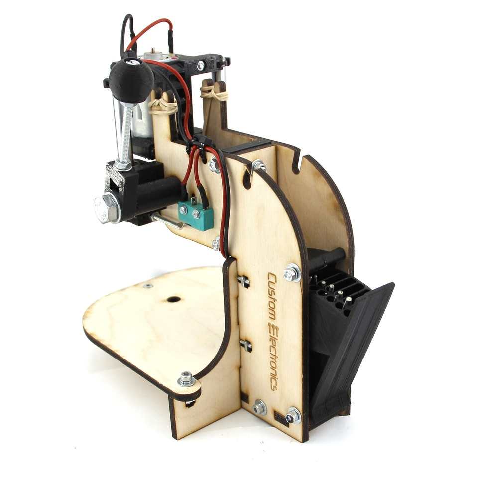
To raise the engine to its original position, two ordinary rubber bands were used. In the upper position, the engine is turned off by itself using a microswitch.
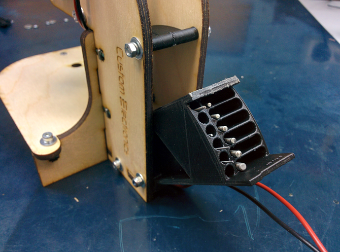
WITH reverse side I provided a place to keep the key and a small case for drills. The grooves in it have different depths, which makes it convenient to store drills with different diameters.
But all this is easier to see once in the video:
It has a small inaccuracy. At that moment I came across a defective engine. In fact, from 12V they consume 0.2-0.3A at idle, and not two, as they say in the video.
Assembly Parts
- Engine with chuck and collet. On the one side chuck this is very convenient, but on the other hand, it is much more massive than a collet clamp, that is, it is often subject to beats and very often they have to be additionally balanced.
- Plywood details. Link to files for laser cutting v dwg format(prepared in NanoCAD) can be downloaded at the end of the article. Simply find a company that deals with laser cutting of materials and transfer the downloaded file to them. I note separately that the thickness of plywood can vary from case to case. I come across sheets that are slightly thinner than 5mm, so I made grooves of 4.8mm.
- 3D printed parts. A link to files for printing parts in stl format can also be found at the end of the article.
- Polished shafts with a diameter of 8mm and a length of 75mm - 2 pcs. Here is the link to the seller with the lowest price per 1m that I have seen
- Linear bearings for 8mm LM8UU - 2pcs
- Microswitch KMSW-14
- Screw M2x16 - 2 pcs
- Screw M3x40 h/w - 5 pcs
- Screw M3x35 slot - 1 pc
- Screw M3x30 h/w - 8 pcs
- Screw M3x30 in / w with a head flush - 1 pc
- Screw M3x20 h/w - 2 pcs
- Screw M3x14 h/w - 11 pcs
- Screw M4x60 slot - 1 pc
- Bolt М8х80 - 1 piece
- Nut M2 - 2pcs
- Nut M3 square - 11 pcs
- Nut M3 - 13pcs
- Nut M3 with nylon ring - 1pc
- Nut M4 - 2pcs
- Nut M4 square - 1 pc.
- Nut M8 - 1pc
- Washer M2 - 4pcs
- Washer M3 - 10pcs
- Washer M3 increased - 26 pieces
- Washer M3 groverny - 17 pieces
- Washer M4 - 2 pieces
- Washer M8 - 2 pieces
- Washer M8 groverny - 1 piece
- Set of mounting wires
- Heat shrink tubing set
- Clamps 2.5 x 50mm - 6 pcs
Assembly
The whole process is shown in detail in the video:If you follow just such a sequence of actions, then it will be very easy to assemble the machine.
This is how the complete set of all components for assembly looks like
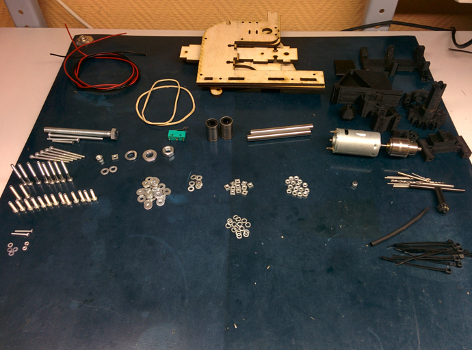
In addition to them, the assembly will require the simplest hand tool. Screwdrivers, hex keys, pliers, wire cutters, etc.
Before starting to assemble the machine, it is desirable to process the printed parts. Remove possible sags, supports, and also go through all the holes with a drill of the appropriate diameter. Plywood parts along the cut line can stain the fumes. They can also be sanded down.
After all the parts are prepared, it is easier to start with the installation of linear bearings. They creep inside the printed parts and screw to the side walls:

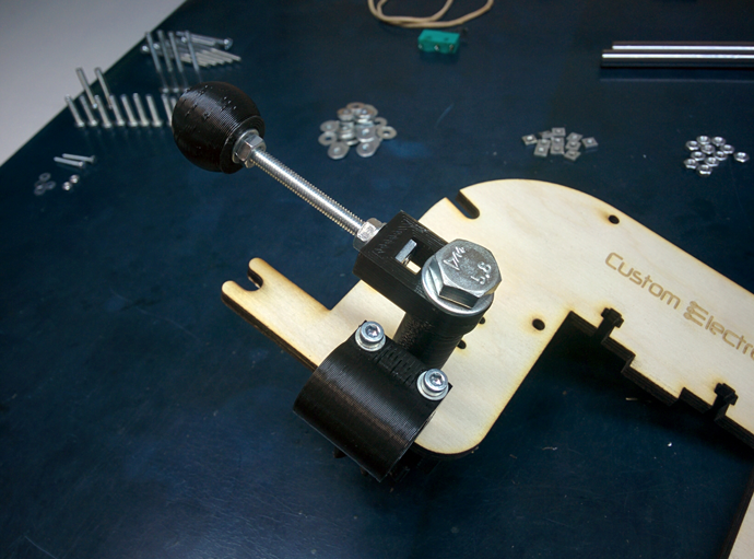
Now you can assemble the plywood base. First, the side walls are installed on the base, and then the vertical wall is inserted. There is also an additional printed piece on the top that sets the width at the top. When driving screws into plywood, do not apply too much force.


In the table on the front hole, it is necessary to make a countersink so that the sunk head screw does not interfere with drilling the board. A printed fastener is also installed at the end.
Now you can start assembling the engine block. It is pressed by two parts and four screws to the movable base. When installing it, make sure that the ventilation holes remain open. It is fixed to the base with clamps. First, the shaft is threaded into the bearing, and then the clamps are snapped onto it. Also install the M3x35 screw, which will press the microswitch in the future.
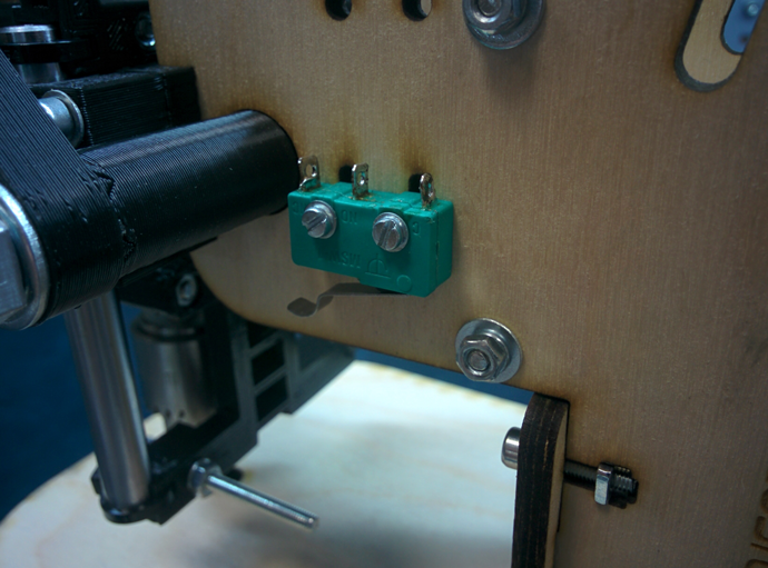
The microswitch is installed on the slot with the button towards the engine. Later, its position can be calibrated.
Elastic bands are thrown over the lower part of the engine and threaded to the "horns". Their tension must be adjusted so that the engine rises to the very end.
Now you can solder all the wires. There are holes on the motor block and next to the microswitch for clamps to secure the wire. Also, this wire can be passed inside the machine and brought out from the back. Be sure to solder the wires on the microswitch to the normally closed contacts.
It remains only to put a case for drills. The top cover must be tightened tightly, and the bottom cover must be tightened very loosely, using a nut with a nylon insert for this.
This completes the build!
Add-ons
Other people who have already assembled such a machine for themselves have made many suggestions. If I may, I will list the main ones, leaving them in the author's form:- By the way, for those who have never worked with such details before, it would be good to remind you that plastic from 3D printers is afraid of heat. Therefore, you should be careful here - you should not go through holes in such parts with a high-speed drill or Dremel. Hands, hands...
- I would also recommend installing the microswitch at a very early stage of assembly, since you still need to be able to screw it to an already assembled frame - there is very little free space. It would not hurt to advise the craftsmen to at least tin the contacts of the microswitch in advance (or even better, solder the wires to them in advance and protect the soldering points with segments heat shrink tubing), so that subsequently, when soldering, the plywood parts of the product are not damaged.
- Apparently I was lucky and the chuck on the shaft turned out to be not centered, which led to serious vibration and hum of the entire machine. I managed to fix it by centering with "pliers", but it's not a good option. since it bends the axis of the rotor, and it is no longer realistic to remove the cartridge, there are fears that I will pull out this very axis in its entirety.
- Tighten screws with lock washers as follows. Tighten the screw until the lock washer closes (straightens). After that, turn the screwdriver 90 degrees and stop.
- Many advise attaching a speed controller to it according to the Savov scheme. It turns the engine slowly when there is no load, and increases the speed when the load appears.


Mixed Personality Disorder: Causes, Symptoms, Types and Treatments
GTA 4 control settings
FAQ on Smuggling in GTA Online
LSPDFR - welcome to the police
The huge map of Grand Theft Auto San Andreas and its secrets