(534.5 kb.)
Available files (1):
| 1.doc | 535kb. | 16.11.2011 08:22 |
1.doc
electr. Version drawing in Compass: Korenchuk Ivan
Basic principles for the development of control programs
for CNC equipment
General principles for constructing programs
CNC equipment is understood as control using programs specified in an alphanumeric code.
When processing on CNC machines, the tool moves along the paths specified in the program.
In this case, for example, for lathes, the movement of the tip of the cutter is programmed, and for milling machines, the movement of the cutter axis.
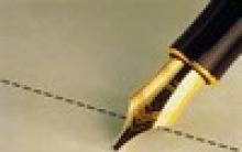
The axis of the cutter moves along an equidistant line, i.e., a line or surface spaced from the surface to be machined by a constant value equal to the radius of the cutter.
the required contour of the part;
equidistant;
cutter.
Two feeds are programmed. Anchor points are selected on the contour being processed, which are those points of the contour at which it changes its character (points 4, 5, 6, 7).
The computer built into the CNC system approximates the movements of the working bodies of the equipment. Specifically approximates a circle with a broken line (between points 6 and 7). Therefore, there is an error .
CNC equipment equipped with either stepper motors, or DC motors (thyristor).
Let N x and N y is the number of pulses along the X and Y axes, respectively, then
 ,
, ,
,
where X and at– pulse prices (discretes), which usually lie within 0.0050.01 mm.
Stepper motors are low-torque and are not used in machine tools. The machines use DC motors, for which it is necessary to calculate the speed of movement along the coordinate axes:
 ,
,  ,
,
where  – time of movement along a straight line at a given point of approximation, [s], ^S– feed rate, [mm/min],
l is the length of the approximation section at a given point, and
– time of movement along a straight line at a given point of approximation, [s], ^S– feed rate, [mm/min],
l is the length of the approximation section at a given point, and
 .
.
Structure of CNC systems
^
Distinguish CNC without feedback and with feedback.
The structure of the control without feedback is as follows:

program carrier;
decoder (reader);
intermediate device (memory);
actuator.
Control structure with feedback:

1, 2, 3 - similar to a device without feedback (see previous figure);
comparing device;
amplifier;
drive unit;
feedback sensor.
Since the control in the control system takes place through several channels, the overall structure of the control system is as follows:

BTK - block of technological commands
program carrier;
magnetic head;
the electronic unit;
channels (controlling movement technological equipment and channel for commands);
drive of the main movement;
coolant supply motor;
machine hydraulic pump motor;
amplifiers;
power drives (DC motors);
feedback sensors;
working bodies of the machine;
lead screws.
Varieties of CNC
Distinguish between positional and contour CNC.
Positional CNC controls only the movement of working bodies to certain points. For example, when drilling holes in printed circuit boards you only need to specify the coordinates of the holes.
Contour controls provide the required speed in the process of moving from one position to another. This speed is the feed rate.
In the designations of metal-cutting machines, it is possible to indicate the type of CNC used. At the end of the designation is indicated:
…C – cyclic program control, control elements are
limit switches, stops, etc.
... F1 - the machine is equipped with a digital indication of the position of the tool.
... F2 - positional CNC.
... F3 - contour CNC.
... F4, ... F5 - machining centers (MC) - multi-operation machines
With positional and contour control, respectively.
Also in the designation of machines there are letters P and M.
P - turret (for example, RF3).

M - the equipment is equipped with a store of elements, which is typical for OTs.

^ CNC Tools
The range of tools for CNC machines (see tables 1 - 5) is based on statistical analysis shapes and sizes of manufactured parts and technological capabilities of machine tools. In specific processing conditions, other tools (tool materials) can also be used.
Drills are used to make holes boring cutters limited range. In most cases, countersinks and reamers are not used. The 7th and 8th grades for holes are obtained by boring (the use of reamers is advisable only in the case of processing large batches of parts).
The outer main surfaces with the formation of straight ledges are formed with a through cutting cutter with angles =95° 1 =5° for roughing and contour cutters with angles =93° and 1 =32° for finishing (see Table 1) .
When processing the internal main surfaces, centering and spiral drills are used, as well as boring cutters with angles =95°, 1 =5° for roughing and boring contour cutters with angles =93°, 1 =32 for finishing . The dimensions of the boring tool are set according to the dimensions of the holes being machined: diameter and length.
For processing blind holes, spade or spiral bottom drills with a diameter of 25, 30, 35, 40, 45 and 50 mm are used.
For the formation of external and internal additional surfaces, slotted cutters, cutters for angular grooves, threaded cutters with an angle of = 60, 55 (for metric and inch threads) are required.
The design of the tool and tool holders should provide the possibility of pre-setting the tool to a size outside the machine, quick and accurate installation of the tool in the working position on the support or in the turret, the formation and removal of chips in the conditions of automatic operation of the CNC machine.
^
1. Tool for processing the outer main surfaces.
| Cutter | Form of the working part | Angles in plan, degrees | cutting material |
|
| | 1 |
|||
| Passage scoring left |  | 95 | 5 | T14K8, T5K10, VK8 |
| Straight scoring right |  | 95 | 5 | |
| Outline left |  | 93 | 32 | T14K8, T15K6, VK6 |
| contour right |  | 93 | 32 |
|
| Outline left |  | 63 | 62 |
|
| contour right |  | 63 | 62 |
|
Note. The contour cutter right (left) is also used for processing additional surfaces.
^
2. Tool for processing internal main surfaces.
| Cutter | Form of the working part | cutting material |
| boring pass |  | T14K8, T5K10, VK8 |
| Boring contour |  | T14K8, T15K6, VK6 |
^ 3. Tool for processing external additional surfaces.
| Cutter | ^
Form of the working part | Dimensions, mm | cutting material |
||
| b | l | D |
|||
| For corner grooves |  | 2x2 | - | - | R18 |
| 3x3 | T5K10, VK8 |
||||
| slotted |  | 1 | 3 | - | R18 |
| R18, T15K10 |
|||||
| 3 | 10 |
||||
| T15K10, VK8 |
|||||
| 6 | 15 |
||||
| For face grooving |  | 3 | 25 | 30 | R18 |
| 150 |
|||||
| 6 | 35 |
| T5K10, VK8 |
||
| 10 | 40 |
|
|||
| Threaded |  | - | - | - | T15K6, VK6 |
| detachable |  | 3 | 35 | - | R18 |
4. Tool for processing internal additional surfaces.
| Cutter | Form of the working part | Dimensions, mm | cutting material |
|||||||
| b | l | L | d |
|||||||
| For corner grooves |  | 2 | - | 60 | To 10 | R18 |
||||
| 3 | 100 | 10-50 |
||||||||
| 5 | 150 | 50 – 100 | T5K10, VK8 |
|||||||
| 8 |
||||||||||
| 200 | St. 100 |
|||||||||
| slotted |  |
| Up to 60 | From 10 | R18 |
|||||
| 3 | 10 | 100 | From 16 |
|||||||
| 6 | 15 | 150 | From 20 | T5K10, VK6 |
||||||
| 10 | 25 | 200 | From 50 |
|||||||
| Threaded |  | - | - | - | - | T15K6, VK6 |
||||
^ 5. Tool for processing holes.
| Drill | Form of the working part | Size, d mm | cutting material |
| centering |  | 6.3 (at D= 25 mm) | R6M5, R18 |
| Spiral |  | 10,1 | R6M5, R18 |
| Lamellar (feather) |  | 25,0 | R6M5, R18 |
Note. For machines with spindle rotation only in one direction, left-handed drills should be used.
^ Structure and format of control programs (CP)
The UE is recorded on the program carrier in the form of a sequence of frames, which are phrases complete in meaning in the coding language of technological, geometric and auxiliary information. Information on the media is stored in a 7-bit ISO code, which provides the recording of commands in the form of letters and numbers. Separate sequences of frames for processing sections of the workpiece are combined into UE chapters, each of which begins with the main frame. The main frame contains initial information about the processing conditions, and from it you can start or resume the operation of the machine according to NC. The remaining frames of the head of the UE carry only a part of the information changed in relation to the previous frames and are called additional frames.
Frames are made up of words arranged in a certain order, and words are made up of characters. The first character of the word is a letter denoting the address, and the remaining characters form a signed number or integer code (Table 6).
6. Designation of addresses.
| Symbols addresses | ^
Address symbol values |
| A, B and C | Angular movements around the X, Y and Z axes, respectively. |
| D | Angular movement around a special axis or third feed function or tool offset function. |
| E | Angular movement around a special axis or a second feed function. |
| F | Feed function. |
| G | preparatory function. |
| H | Indefined. |
| I, J and K | Interpolation parameters or thread pitches respectively along the X, Y and Z axes. |
| L | Indefined. |
| M | Helper function. |
| N | Frame number. |
| P and Q | Third functions of movements parallel to the X and Y axes, respectively, or tool offset parameters. |
| R | Rapid Z-axis movement or third Z-axis movement function or tool offset parameter. |
| S | ^
Main movement speed. |
| T | tool function. |
| U, V and W | The second functions of displacements parallel to the X, Y and Z axes, respectively. |
| X, Y and Z | Movements, respectively, along the X, Y and Z axes. |
Note. If the symbols D, F, P, Q, R, U, V, W are not used by the CNC with the values given in the table, they can be used as other special values.
The UE frame contains the word "Frame number" and one or more information words. Information includes the words "Preparatory function", "Dimensional movement", "Feed function", "Main movement speed", "Tool function" and "Auxiliary function". In the frame, these words have the same sequence.
^
Frame number
The word "Frame number" serves to designate an elementary section of the UE and is auxiliary information. The frame number is given by the address N and a decimal integer. Sequential numbering of frames is rational, however, any transitions of numbers are allowed and only their non-recurrence within one UE is stipulated. When numbering new frames inserted during editing, in order to avoid changing the previously established sequence of their numbers, it is practiced to record new numbers using higher digits of decimal numbers. For example, if several new frames need to be inserted after frame N107, they can be numbered N10701, N10702, N10703, etc. In the main frame, instead of address N, the character “:” is provided, which can be used to stop when rewinding the punched tape.
^
Preparatory Functions
The word "Preparatory function" defines the operating mode of the CNC. These words are given by the address G and a two-digit decimal number (Table 7.8).
^ 7. Purpose of preparatory functions .
| preparatory function | Group | Meaning |
| G00 | 1 | Positioning. Moving at high speed to a given point. The previously set cutting feed is not cancelled. Axes movements can be uncoordinated. |
| G01 | 1 | Linear interpolation. Traversing at programmed feedrate in a straight line to a point. |
| G02 and G03 | 1 | Circular interpolation. Arc movement respectively in negative and positive direction with programmed feedrate. |
| G04 | - | Pause. Exposure in working out for a certain time set on the remote control or set in the frame. |
| G06 | 1 | parabolic interpolation. Parabolic movement with programmed feed. |
| G08 | - | Overclocking Smooth increase in feed rate to its programmed value at the beginning of the movement. |
| G09 | - | Braking at the end of the frame. Smoothly decrease the feedrate to a fixed value when approaching the set point. |
| G17,G18,G19 | 2 | processing plane. Specifying the XY, ZX and YZ planes respectively for functions such as circular interpolation, cutter compensation, etc. |
| G33,G34,G35 | 1 | Thread. Threading, respectively, with constant, increasing and decreasing pitches. |
| G40 | 3 | Cancels the tool offset specified by one of the functions G41-G52. |
| G41 and G42 | 3 | Tool diameter or radius compensation in contouring control. The cutting tool is located respectively to the left or to the right of the surface to be machined, when viewed in the direction of tool movement. |
| G43 and G44 | 3 | The tool diameter or tool radius offset is respectively positive or negative. Indication, respectively, about the addition (or subtraction) of the offset value of the tool installed on the console with the coordinates specified in the frames. |
| G45-G52 | 3 | Tool diameter or radius compensation for straight shaping G45 / , G46 /-, G47-/-, G48-/ , G49 0/ , G50 0/-, G51 /0, G52-/0. The values “ ”, “-” and “0”, respectively, indicate that the values set on the remote control will be added to the coordinates specified in the frames, or these values will not be taken into account. |
| G53 | 4 | Cancels a linear shift specified by one of the functions G54-G59. |
| G54-G59 | 4 | Linear shift respectively in X, Y, Z, XY, ZX and YZ. Correction of the length or position of the tool by the value set on the console. |
^ 7. Assigning preparatory functions (continued) .
| preparatory function | Group | Meaning |
| G60 and G61 | 5 | Precise positioning. Positioning within one or two of the tolerance zones, as well as the choice of approach side when positioning. |
| G62 | 5 | fast positioning. Positioning with a large tolerance zone to save time. |
| G63 | - | Thread cutting with a tap. Positioning with spindle stop when the specified position is reached. |
| G80 | 6 | Cancels the canned cycle specified by one of the G81-G89 functions. |
| G81-G89 | 6 | Constant cycles. Frequently used command sequences in hole machining. The composition of the canned cycles is given in the supplementary table. |
| G90 | 7 | Absolute size. Counting of movements in the absolute coordinate system with the origin at the zero point of the CNC system. |
| G91 | 7 | Size in increments. Counting movements relative to the previous programmed point. |
| G92 | - | Setting absolute position accumulators. |
| G94 and 095 | 8 | The unit of measurement is respectively mm/min and mm/rev. |
| G96 | 9 | The unit of measure for cutting speed is m/min. The programmed value of the cutting speed is maintained automatically by the regulation of the spindle speed. |
| G97 | 9 | Main motion unit RPM |
8. Table for canned cycles.
| Constant cycle | Action before processing | Movement in progress | Action after processing | | Typical use |
| G81 | - | working stroke | - | Fast withdrawal | drilling, centering |
| G82 | stand up | drilling, countersinking |
|||
| G83 | Peck feed | - | deep drilling |
||
| G84 | Enable spindle rotation in a given direction | working stroke | Reverse spindle | Withdrawal at work filing | Threading tap |
| G85 | - | - | Boring |
8. Table for canned cycles (continued).
| Constant cycle | Action before processing | Movement in progress | Action after processing | Movement to starting position | Typical usage |
| G86 | Turning on the spindle | working stroke | Spindle stop | Fast withdrawal | Boring |
| G87 | Retraction manually |
||||
| G88 | Wait, spindle stop | ||||
| G89 | - | stand up | Withdrawal at work filing |
Unspecified preparatory function codes are for individual use at the discretion of the CNC developers. The group number, located in the second column, indicates that the G function is valid until it is replaced or canceled by another function from the same group. A dash in this column means that the function is active only in the block in which it is specified. The preparatory functions are written in the frame sequentially one after another in ascending order of their code numbers. More than one preparation function from each group cannot be recorded in a block.
^
Let's show the action of some preparatory functions in the figure:


![]()
^
Secondary functions
The word "Auxiliary function" defines a command to the executive body of the machine or CNC. Auxiliary functions are specified by words with the address M and a two-digit decimal code number (Table 9).
^ 9. Purpose of auxiliary functions .
^ 9. Assigning auxiliary functions (continued) .
| M02 | P | End of UP. Spindle stop and cooling off. Bringing the control device to its original state and returning the working bodies of the machine to its original position, as well as pulling the punched tape glued into a ring, or rewinding it. |
| M03 and M04 | * | Spindle rotation clockwise or counterclockwise. Turning on the spindle respectively in the negative and positive direction of rotation. |
| M05 | P | Spindle stop. Stop in the most efficient way, such as braking. |
| M06 | Tool change. Command to change the tool manually or automatically. The tool is not searched. Can automatically turn off the spindle and cooling. |
|
| M07 and M08 | * | Turn on cooling. Includes cooling No. 2 and No. 1, respectively. |
| M09 | P | Turn off cooling. Cancels commands given by functions M07, M08, M50 and M51. |
| M10 and MP | * | Clamp and unclamp. Refers to the clamping devices of the movable parts of the machine, such as the table, chuck, etc. |
| M13 and M14 | * | Spindle rotation clockwise and counter-clockwise, as well as the inclusion of cooling. Same as M03 and M04, but with cooling enabled. |
| M15iM16 | Move " " and "-". Used to set respectively the positive and negative direction of the movement programmed in this block. |
|
| M17 | P | End of subroutine for CNC with built-in memory. Transfer of control to the main program after all runs of the subroutine have been completed. |
| M19 | P | Spindle stop at the specified position. Command to stop the spindle at a certain angular position. |
M20 | P | End of a subroutine, which is used as a repeatedly read program chapter. |
| M30 | P | End of tape. The same as M02, but with the possibility of accessing the second reader of information from the punched tape. |
| M31 | Block bypass. Command to temporarily cancel the lock. Only effective in the frame in which it is recorded. |
|
| M36 and M37 | * | Delivery range. Sets the range of feeds, respectively, No. 1 and No. 2 by switching the kinematic connection. |
| M38 and M39 | * | Spindle speed range. Sets the speed range for spindle #1 and #2, respectively. |
| M50 and M51 | * | Turn on cooling. The inclusion of cooling, respectively, No. 3 and No. 4. |
| M55 and M56 | * | Tool linear offset. Linear displacement of the tool, respectively, to positions No. 1 and No. 2. |
| M61 and M62 | * | Linear displacement of the workpiece. Linear displacement of the workpiece, respectively, to positions No. 1 and No. 2. |
| M71 and M72 | * | Angular displacement of the workpiece. Angular displacement of the workpiece, respectively, in position No. 1 and No. 2. |
Unspecified codes are not defined and may be used at the discretion of the designers of specific CNCs.
Most auxiliary functions (marked with an asterisk in the second column) are executed before the start of the movements programmed in the same block, and remain in effect until they are canceled or replaced by commands of the same purpose. The M functions executed after the movements specified in the block are marked with the letter P in the same column. In one frame, in ascending order of code numbers, several commands can be written to different executive bodies CNC machine.
^
An example of developing a program for a CNC machine

% N001 S03 T01 M03 - third spindle speed, first tool, counterclockwise spindle rotation
N002 M06 - tool check pause
N003 G60 - precise positioning
N004 G91 - incremental size count
N005 G00 X-030045 - move to point 1
N006 G61 Z-015000 - Rapid move to point 2
N007 G01 Z-045000 F32 M07 - move to point 3 at work feed and turn on oil mist
N008 G01 X 004960 Z-035000 - move to point 4 with linear interpolation
N009 Z-025000 - move to point 5
N010 G60 - precise positioning
N011 G00 X 025085 M09 - rapid travel to point 6, shutdown of the cooling system
N012 G00 Z 120000 M02 - rapid movement to point 0, end of program
The essence of program control of metalworking machines is the development of control programs in numerical form, which allow solving geometric, logical, technological and terminal problems in relation to a specific type of CNC.
The solution of the geometric problem provides the shaping of the part by the corresponding movement of the tool or workpiece.
The logical task is to ensure that the automation of the machine is controlled in a certain logical order.
The technological task is aimed at ensuring the specified quality of the resulting part.
The terminal task is to provide communication with the operator through terminal devices - terminals.
As applied to the H-22-1M system, these tasks are solved in the manner described below.
UE - a set of commands in the programming language, corresponding to a given algorithm for the functioning of the machine for processing a particular workpiece.
When turning, the mutual movement of the tool (the top of its blade) is carried out along a certain trajectory (the contour of the workpiece). Separate sections of the workpiece contour can be considered as geometric elements (line segments, circular arcs, etc.). The intersection points of geometric elements are called geometric reference points. Each reference point in the selected coordinate system can be described by numbers (coordinates). The combination of numbers that define a number of successive positions of the tool is the main part of the UE. The coordinates of geometric reference points can be absolute, i.e. set for each point relative to the zero point, or relative (set in increments), set in the direction of tool movement from one reference point to another. When programming, it is necessary to specify the speed of movement of the tool between individual reference points, a number of auxiliary technological commands. The points of the calculated trajectory, at which the law that describes the conditions for the flow of the technological process changes, are called technological reference points.
Each UE begins with the character% - "beginning of the program".
Designation "number" control program should be located immediately after the symbol "beginning of the program". When placing several UEs on the program carrier, it is allowed to write one more character “program start” before the symbol “beginning of the program”. Numbering of program blocks starts from the next block.
Each frame contains geometric and technological data that must be provided when machining the section of the workpiece between two reference points.
The basic numerical unit of the UE is the frame. The block is perceived by the CNC system as a whole and contains at least one command. The frame has a specific format for a specific type of CNC. The frame is made up of words. Each word contains specific information (command). A word consists of an address (Latin capital letter) and data (mathematical sign "+" or "-" and numbers). The first word in a frame is always "frame number" - address N, data - a three-digit number. The number serves to systematize the program and has no effect on its course. The rest of the words in the frame can be arranged arbitrarily, but the following sequence of words (at their respective addresses) is recommended:
N, G, X, Z, I, K, F, S, T, M, L.
Using the words X, Z, I, K, L, a geometric problem is solved.
The words G, F, S, T, M provide a solution to the logical problem.
The solution of the technological problem in the system is not provided.
The terminal task is determined by the design of the system itself.
The main stages of development of the control program.
1. Complex "CNC Machine"
V general view The structure of the "CNC Machine" complex can be represented as three blocks, each of which performs its task - a control program, a CNC device and a machine tool.
All blocks of the complex work interconnectedly in a single structure. The control program contains an enlarged coordinated description of all stages of the geometric and technological formation of the product. From an information point of view, the main thing in this description is that. that it does not allow for ambiguous interpretations. In the CNC device, information is transmitted in accordance with the UE. and then used in the computational cycle, the result of which is the creation of operational commands in real machine time.
The machine is the main consumer of control information, the executive part. control object. a in a constructive sense - a supporting structure on which mechanisms are mounted with automatic control adapted to receive operational commands from the CNC. Among such mechanisms are primarily those that are directly involved in the geometric shaping of the product. These are the mechanisms of coordinate feeds, the directions of which are different.
In the control process, feed mechanisms require the greatest amount of processing of calculation information, therefore, the complexity of CNC devices largely depends on the number of controlled coordinates, on the complexity of the geometric problem of shaping.
The main tasks solved by CNC systems:
· Input and storage of system software. In devices of the lower classes, it is inherent in the design and cannot be changed. V modern systems ah can be entered and configured from the outside and is intended for machines of different classes.
· Input and storage of control programs in a non-volatile device.
frame interpretation. 2 frames are read - the first is processed, the second is preliminarily analyzed for continuous operation. Modern systems read and analyze up to 1000 frames.
· Interpolation. The CNC calculates intermediate points with the specified accuracy. Modern NURBS systems receive an electronic model of the workpiece from the CAD / CAM system, curved surfaces are transmitted in the form of splines and polynomials, processed by the device itself and converted into signals to feed drives.
· Feed drive control. In addition to controlling the movement along the trajectory, additional modes for coordinating the true position of the working bodies with the control system, zeroing the machine, braking control.
Control of the drive of the main movement (on, off, angle control, speed stabilization)
logical control
Tool size compensation
Tool change
· For modern systems it is possible to correct errors of measuring and mechanical devices, adaptive control of processing, accumulation of statistical information, automatic built-in control, communication with a PC of the upper level, technical diagnostics.
Stages of preparation of control programs.
The development of a technological process for CNC equipment requires more detail in solving all technological problems. It is necessary to divide the operation into steps by reference points. A step is a movement of the tool along a geometric element, during which there is no change in modes. Technological commands define the conditions for performing movements. The sequence of elementary movements and technological commands determine the content of control programs.
The development of the technological process consists of three stages:
Route TP;
Operational TP;
· Development of UE.
The choice of parts for processing on CNC machines in mechanical engineering technology. The main factor is the economic benefit from:
Reductions in piece-calculation time
Machine time
Auxiliary time
Improving product quality, etc.
The sequence of development of UE:
The sequence of development of UE (manual programming):
Sequential programming of individual processing steps.
1. Separation of the operation into transitions.
2. Determining the basing of the part.
3. Determining the sequence of transitions (if the surface is machined with an accuracy of more than 11 grades, it is advisable to perform a finishing pass with a separate tool). The result is an operating card
4. Purpose of the tool. In addition to the type of cutting tool, you must specify the block number, determine the orientation of the cutting edge and its position relative to the datum point. This allows you to get a tool setting chart.
5. Separation of transitions into moves.
6. Calculation of cutting conditions
7. Construction of the trajectory of movement of each tool with indication of reference points
8. Calculation of coordinates of control points.
9. Definition of technological commands
10. Program coding
11. Program debugging and test part processing, editing.
Fundamentals of CNC programming. (ISO 6983 standard for SINUMERIK 840D, 810D, FMNC controls).
The generation of these control systems uses new programming methods along with the old commands. These include DIN66025 commands and so-called high-level language commands.
Development and implementation process technological processes and control programs covers the stages of work from construction mathematical models parts and blanks according to the provided documentation and until the receipt of a proven technological process for manufacturing parts on CNC equipment. The approaches used by the specialists of Clio-Soft LLC are the result of many years of experience in the development and implementation of TP and NC processing of parts on modern CNC equipment.
Construction of mathematical models of parts and workpieces

The construction of mathematical models of parts and blanks is carried out in the NX "Modeling" environment in accordance with the provided technical documentation. After completing the work on the construction of mathematical models, the concept of the technological process is developed machining parts on CNC machines.
Tooling design
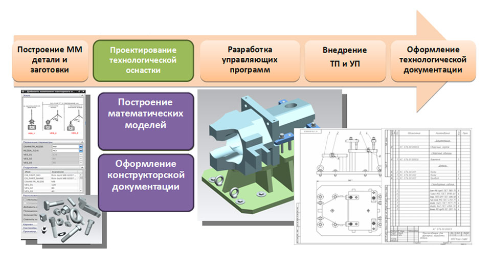
Designing a special technological equipment for fastening blanks in the working area of CNC equipment is carried out in accordance with the developed concept of the technological process of machining a part in the “Modeling” and “Assembly” NX environment. When building mathematical models of tooling, databases of standard fasteners and elements of machine tools developed by Clio-Soft LLC are used.
After constructing mathematical models for technological equipment, design documentation is drawn up in the NX "Drafting" environment using the settings developed by Clio-Soft LLC, which allow drawing up design documentation in accordance with ESKD standards. After registration, the design documentation is transferred to production for the manufacture of technological equipment, and the technologist proceeds to work on the next stage - the development of control programs.
Development of control programs

The development of control programs begins with the selection of a cutting tool and the generation of tool paths in the NX Machining environment. If a limited list of tools is available, the appropriate NX databases can be used. The developed trajectories are output through the postprocessor and NC files are generated, which are checked in the off-machine control system (ISV) directly in the NX Processing environment. The use of the built-in off-machine control system UE is a guarantee of the quality of the performed check, since all changes made in the CAM part are automatically taken into account in the process of machining simulation.
Implementation of TP and PM on CNC equipment
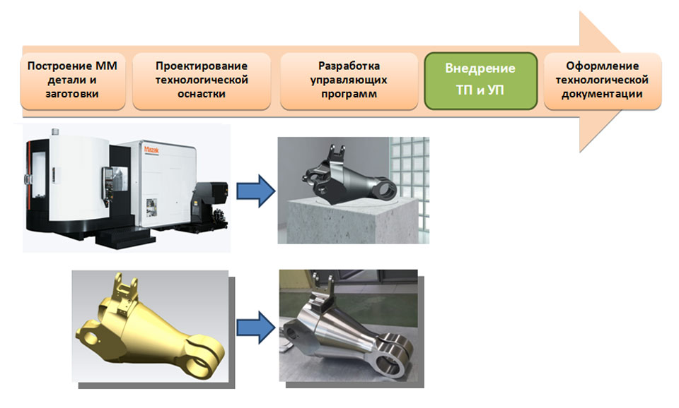
At the stage of implementation of technological processes for machining parts on CNC equipment and control programs, cutting conditions are optimized and the concept of the technological process is developed. The result of the implementation stage is a streamlined technological process of machining a part on CNC equipment, which is documented at the stage of processing technological documentation.
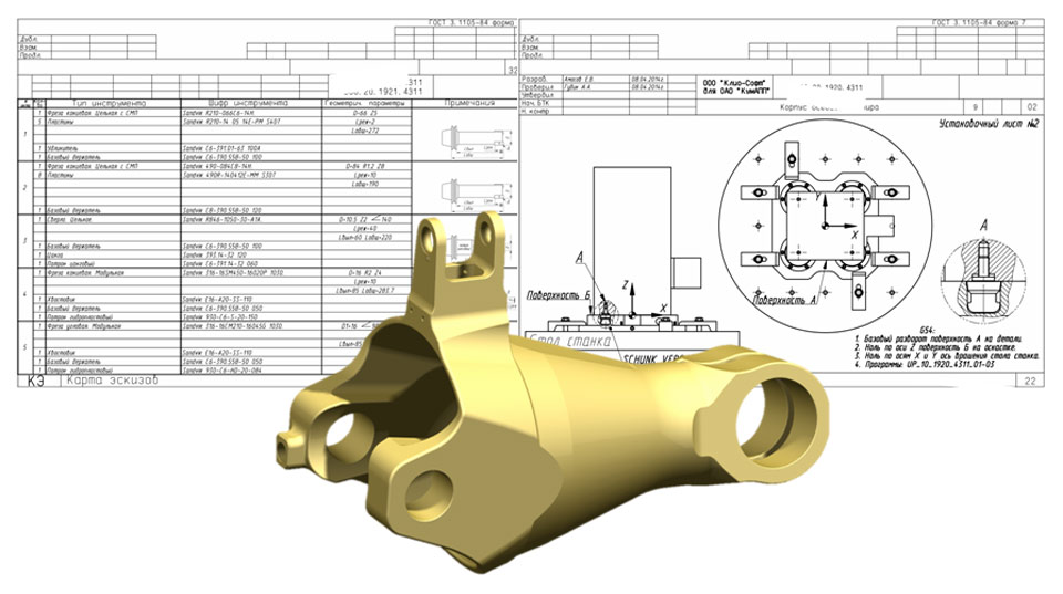
Registration of technological documentation

Registration of technological documentation for the operations of machining parts on CNC equipment is carried out directly in the processing file in the NX environment using the OSST software developed by Clio-Soft LLC, which allows you to draw up technological documentation in accordance with the requirements of the ESTD. In this case, all information on the parameters of the cutting tool and tooling, cutting modes is inherited from the operations of generating trajectories, and all the necessary sketches are drawn up in the "Drawing" module directly in the processing file. The obtained data are supplemented with the necessary textual information. Thus, at the output we get a set of technological documentation, associative with the NX processing file. That is, when making changes to the processing project, after the output of the technological documentation, all the changes made will be taken into account and displayed in the new set of documentation.
Software package for the development of TP and NC for CNC equipment
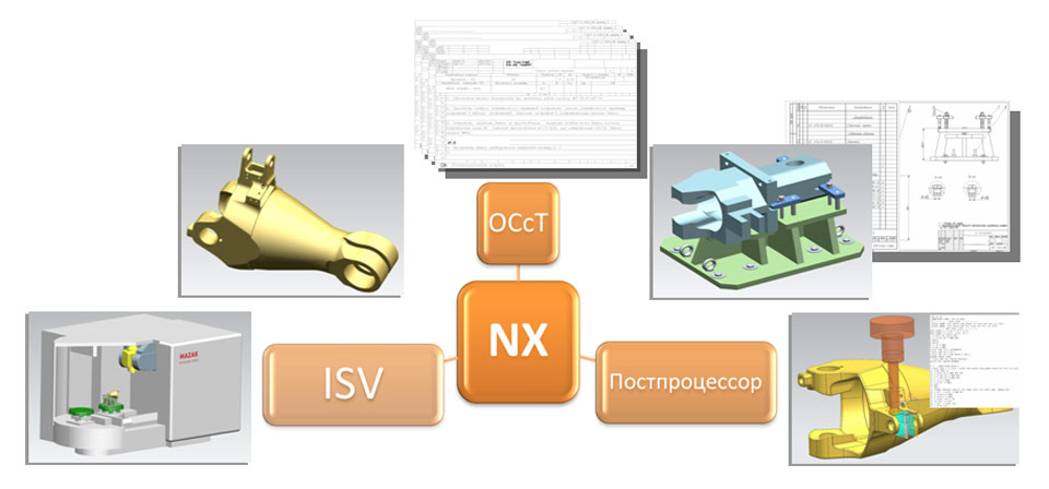
When using the considered software package and methodology for the development and implementation of technological processes and control programs for processing parts on modern CNC equipment, technologists get the opportunity to perform work in a single information environment, which reduces the time for mastering new products and improves the quality of work by eliminating the need to duplicate information in various systems. In addition, when performing the entire range of work by one person, the need to transfer information between co-executors is eliminated, which increases the level of responsibility of the technologist and, accordingly, leads to an increase in the quality of work.


History of sky lanterns
Job description: concept, purpose, structure, procedure for compiling and formalizing Purpose and content of job descriptions for managers
Interview questions What job are you going to work on?
What to do if the boss criticizes all the time If the boss does nothing
How to understand: will the kitten be fluffy?