Modern machine-building production is hard to imagine without CNC machines. program management. Today they are widely used both in industrial giants and in small enterprises. Undoubtedly, the successful development of the engineering industry is impossible without the active use of CNC equipment and production automation.
Tool for processing external main surfaces
The following tools were used. All programming is done on paper and then the machine is entered. The programmer has extensive experience in programming and using microcomputers. The processing steps were as follows. cavity processing. The results discussed below refer firstly to the level of training and finally to the tests carried out in-house.
At the end of the training, six participants were assessed individually, according to the previously proposed questions. Comparing the two evaluated forms of programming, more time is observed in the "program development" phase with the help of a prototype. However, in the “error reporting and debugging” phases, the prototype represents a significant advantage over the manual programming practices adopted by the three companies. During testing, it was also found that the build time of the processing program using the prototype can be significantly reduced as the user becomes accustomed to its editing and modeling environment.
The increase in the fleet of CNC machines leads to an increase in requirements for the technological preparation of production, including the quality of the development of control programs (NC).
Today, all major CAD developers as part of their software systems offer modules for the development of NC programs for CNC machines. The advantages of these modules include the fact that, being integrated into computer-aided design systems and, accordingly, ensuring the correct exchange of models between design and technological modules, they allow you to successfully develop NC for the main types of metalworking equipment with standard technological capabilities - for milling, turning and electroerosive machines . The disadvantages of many systems are the need for highly qualified technologists to work in a CAM system, often an uninformative user interface, the need to perform numerous manual operations, insufficiently developed program diagnostic functions to detect errors, limited opportunities for creating NC programs for the most modern or unique species equipment.
Software package for the development of TP and NC for CNC equipment
In machine A, the machine was stopped for 27 minutes to manually install the program into memory and to run tests. The use of the prototype this time was only 7 minutes, which reduced it by more than 3.8 times. In the tests conducted at Company B, the programmer knew little about machine resources. This entailed the development of an extensive program based only on primitive functions such as linear and circular interpolations. Using subroutines or subroutines will also mean reduced programming time.
To solve all these problems, the developers of specialized software (software) undertook. For example, to check and optimize UE, the engineering and consulting company SOLVER (SOLVER) suggests using the Vericut software package from CGTech (USA), which reduces processing time by 30-50%.
In addition, the market for software products for production offers software for automated preparation of NC, which we will discuss in more detail.
Convenient user interface: easy software development, rapid development of UE
However, these methods were unknown. At Company C, the importance of eliminating the task of typing directly on the machine's interface was again tested. It is noted that this stage significantly contributed to the increase in preparation time, since the machine remained stationary during the typing process.
For most of these options, the format is 3, which has a dot as the decimal separator. If a period is not typed, the command aligns the digits from right to left, implying unwanted side effects. With the prototype, this problem does not exist, since the formatting of all parameters of this programming function occurs automatically. It has been verified that several companies have a very expressive family of parts with low geometric complexity that can be machined using this approach.
PartMaker: Automated NC Development
For the automated development of NC programs for CNC metalworking equipment, SOLVER offers (for the first time in Russia) to use the PartMaker software package from IMCS (USA). Along with the preparation of NC programs for the traditional group of metalworking machines (lathes, milling machines and EDM), this modern and efficient software makes it possible to develop programs for the most modern and unique equipment, including automatic longitudinal turning machines (SwissType) and multi-purpose turning and milling centers .
These companies, mostly small and medium-sized, were characterized as providing processing services for serial products in the automotive chain. In this context, it can be concluded that the evaluated computational prototype represents a viable alternative to reducing the overall processing time compared to purely manual programming.
General algorithm for drilling holes in a matrix. Companies providing processing services in the state of Paraná? Network usage. How many and where are the machines in Brazil. Machines and Metals, December. Benefits: Academic history: Complete technical course.
The modular structure of PartMaker allows you to purchase only the software that is relevant for the enterprise at the moment, and retrofit the software package with new modules as needed. The software includes five main modules for the development of UE:
For automatic longitudinal turning machines - SwissCAM;
For turning and milling machines - Turn-Mill;
This is a new option - for high-speed threading, engraving and grinding, machine tool manufacturing, component processing and manufacturing and other related industries. This device saves up to 70% energy compared to conventional braking resistors.
This makes the system faster and more efficient without time delays. To learn more, check out the documents below and request a technical visit by clicking here. The days when a machine manufacturer could offer the same standard machine for years or even decades are long gone and machine manufacturers are left with many software options that they cannot support in long term. In order to remain masters, they must now take a new approach to managing machine parameters.
For lathes - Turn;
For milling machines - Mill;
For EDM machines - Wire EDM.
Convenient user interface: easy software development, rapid development of UE
The main advantage of PartMaker is the ease of creation and verification of UE. The software runs under Windows. To simplify and speed up the development of UE, a system of graphic and text prompts is used. In addition, PartMaker uses a machining database to store manufacturing experience on cutting tool usage, cutting conditions, and repetitive operations. All this facilitates the development of software and allows the technologist (rather than a programmer) to quickly get trained and start developing high-quality programs.
The machine manufacturer must reactivate the development process and change the machine program. “It takes time, costs and opens the door for possible errors". Machine manufacturers whose customers want to have different variants the same machine, face an even bigger problem.
Hardware independent solution
This avoids errors in the machine program when implementing an option or setting. In addition, it becomes much easier to manage machines with multiple options. No need to re-open the original project or use the development tool.
Increasing flexibility in the use of web technologies
If necessary, they can also be imported back into the original automation project. Just measure your energy consumption. Customize instead of programming. It can also be included in the visualization of the machine.For programming in PartMaker, use modern technique visual programming. Details with complex processing are divided into groups of planes and surfaces of revolution, and with the help of pictures-tips, the desired type of processing is selected. The processing strategy is set by the user. For example, you can complete a full cycle of processing one surface, and then move on to processing another, or process all surfaces with one tool, replace it with the next one (according to the developed technology) and process all surfaces again.
Save time and money by starting software development before hardware is complete, reusable software modules in several projects, function checks through simulation and form commissioning module.
Accelerate time to market by automatically generating code from machine simulation, using configuration data from electrical design software, and collaborating efficiently to support modular software development activities.
Visualization of processing is possible both at the stages of creating technological transitions, and for the entire program as a whole. Simulation of processing processes is carried out on the computer screen with a dynamic three-dimensional demonstration of material removal. It is possible to rotate, scale and change the point and panorama of observation. In this case, you can observe the simultaneous operation of several tools, as well as the process of transferring the part to the counter spindle. For the workpiece, it is possible to set the translucency mode, as well as create a cut that allows you to see the process of processing internal cavities or closed areas. With four-axis machining, rotation of the workpiece around the tool can be observed. For Swiss-type lathes, the software simulates the movements of the bar inside the guide bushing, allowing you to see the actual machining process taking place on the machine.
Reusability improvement
Fully graphical and system hardware configuration and software modulation at all levels simplify the development of machines and systems that benefit from pre-programmed technology components. His sustainable and efficient approach to software development helps ensure high quality, low development costs, and reduced marketing timelines despite the ever-increasing complexity of products. It requires the highest quality, long service life and low operating and maintenance costs.
PartMaker has its own built-in graphics editor for creating mathematical models of machined parts using graphic primitives (points, lines, arcs, chamfers, etc.). The user interface is designed in such a way as to facilitate and speed up the process of creating model geometry as much as possible. This is facilitated by standard Windows commands: "Copy", "Cut", "Paste", etc. You can perform corrective operations such as shifting and rotating the image. It is also possible to import 2D models into PartMaker in DXF format and three-dimensional models from any CAD/CAM system, including Pro/Engineer, AutoCAD, SolidWorks, Unigraphics, etc. If necessary, imported models can be modified by a technologist and then returned back to the design system.
Machines and systems can meet these requirements and offer real added value for budgetary outcomes only with increased complexity. Increasing the time spent planning, developing and delivering products is not an option as fierce competition forces companies to gain technological advantages.
Paradigm shift to success. Parallel design is one of the keys to time for accelerated development. This is related to software development, once the specifications are determined at the same time and simultaneously with the development of mechanical and electrical systems. In addition, several programmers must work simultaneously on various aspects of the overall software solution.
Development of UE for machining
Programming machining PartMaker conducts technological transitions depending on the type of processing (turning or milling), including for turning-milling centers and automatic longitudinal turning, and includes the following features:
2-axis milling with 3-axis tool positioning, machining of pockets with any number of ledges, taking into account climb or upstream milling, as well as the introduction of an offset mode;
Another key factor in achieving ambitious development goals is the reuse of existing and field-proven software elements, whether they are business-class modules or pre-programmed technology components. this saves the time and commitment required for programming, testing and certification.
Greater learning rate
This allows software developers to quickly and efficiently master the increasing complexity of mechatronic systems without compromising quality. Full featured user interface for every aspect of automation projects.
Integrated software design
- Intuitive user guide.
- Immediately available for use.
contour milling;
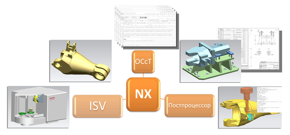
The process of development and implementation of technological processes and control programs covers the stages of work, starting from the construction of mathematical models of parts and blanks according to the provided documentation and to obtaining a proven technological process for manufacturing parts on CNC equipment. The approaches used by the specialists of Clio-Soft LLC are the result of many years of experience in the development and implementation of TP and UP for processing parts on modern equipment with CNC.
Implementation of TP and PM on CNC equipment
The software developer is now faced with an unprecedented array of hardware options, both on the machine and on the desktop. To keep up with ever-increasing complexity, feature density and various kinds activities involved in each machine, the methods of development have undergone a "forced and profound evolution."
Marketing timing goals prevent you from waiting for the machine to be built and the hardware to be installed, and then to develop the software as soon as possible and with very high time pressure. While currently available programming tools are capable of accelerating programming per se, the greatest potential for efficient and sustainable product development lies in the melting of mechanical, electrical, and software, and in handling machines and systems, both with integrated creations and with them.
Construction of mathematical models of parts and workpieces
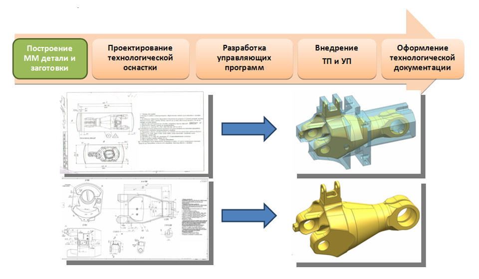
The construction of mathematical models of parts and blanks is carried out in the NX "Modeling" environment in accordance with the provided technical documentation. After completing the work on the construction of mathematical models, the concept of the technological process of machining parts on CNC equipment is developed.
Object Oriented Programming
Benefits of object-oriented programming. The behavior of a machine or system is determined by its software. It is the ultimate way to manage every process and every movement, manage vital messages and data, and ensure the right response to user interactions, third-party system instructions, and sensor-related events.
An example of developing a program for a CNC machine
Therefore, software development can be based on specifications used for mechanical design, even if there is a possibility that many details may differ. You can take advantage of object-oriented programming to create structures and variables to populate with real values.
Tooling design
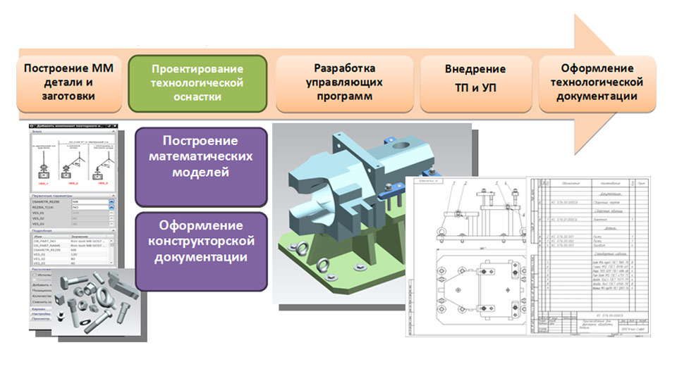
Designing a special technological equipment for fastening blanks in the working area of CNC equipment is carried out in accordance with the developed concept of the technological process of machining a part in the “Modeling” and “Assembly” NX environment. When building mathematical models of tooling, databases of standard fasteners and elements of machine tools developed by Clio-Soft LLC are used.
Development of UE for machining
Automated code generation from simulation models helps build software with mechanical design at a very early stage in the development process. In the case of electrical planning, the numerous advantages associated with the possibility of avoiding unnecessary obligations and the risk of errors associated with having two versions of master data are numerous. This bidirectional exchange ensures that both sets of data are kept up to date.
Sustainable savings thanks to reusable modules. Integrated tools help to work in a team, and automatic control versions reduces the time spent on coordination and documentation. Various useful features such as automatic generation of master data, visual hardware configuration and object-oriented programming make software development more creative.
After constructing mathematical models for technological equipment, design documentation is drawn up in the NX "Drafting" environment using the settings developed by Clio-Soft LLC, which allow drawing up design documentation in accordance with ESKD standards. After registration, the design documentation is transferred to production for the manufacture of technological equipment, and the technologist proceeds to work on the next stage - the development of control programs.
Development of control programs
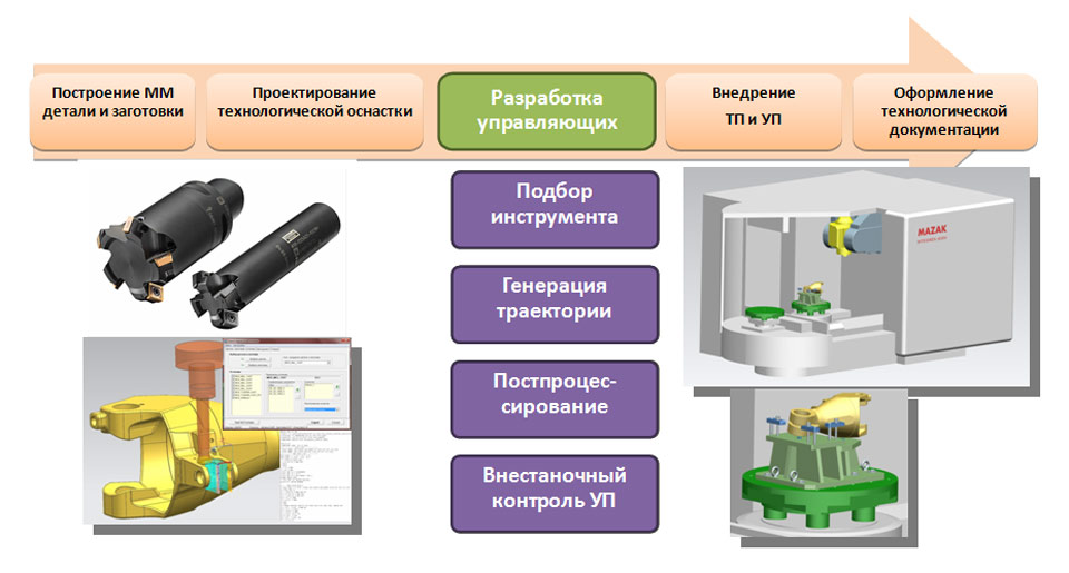
The development of control programs begins with the selection of a cutting tool and the generation of tool paths in the NX Machining environment. If a limited list of tools is available, the appropriate NX databases can be used. The developed trajectories are output through the postprocessor and NC files are generated, which are checked in the off-machine control system (ISV) directly in the NX Processing environment. The use of the built-in off-machine control system UE is a guarantee of the quality of the performed check, since all changes made in the CAM part are automatically taken into account in the process of machining simulation.
Implementation of TP and PM on CNC equipment
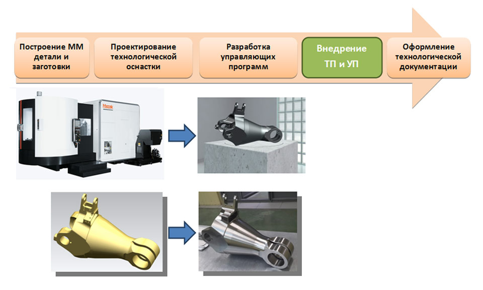
At the stage of implementation of technological processes for machining parts on CNC equipment and control programs, cutting conditions are optimized and the concept of the technological process is developed. The result of the implementation stage is a streamlined technological process of machining a part on CNC equipment, which is documented at the stage of processing technological documentation.
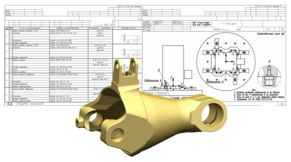
Registration of technological documentation
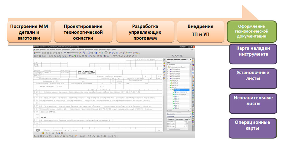
Registration of technological documentation for the operations of machining parts on CNC equipment is carried out directly in the processing file in the NX environment using the OSST software developed by Clio-Soft LLC, which allows you to draw up technological documentation in accordance with the requirements of the ESTD. In this case, all information on the parameters of the cutting tool and tooling, cutting modes is inherited from the operations of generating trajectories, and all the necessary sketches are drawn up in the "Drawing" module directly in the processing file. The obtained data are supplemented with the necessary textual information. Thus, at the output we get a set of technological documentation, associative with the NX processing file. That is, when making changes to the processing project, after the output of the technological documentation, all the changes made will be taken into account and displayed in the new set of documentation.
Software package for the development of TP and NC for CNC equipment
When using the considered software package and methodology for the development and implementation of technological processes and control programs for processing parts on modern CNC equipment, technologists get the opportunity to perform work in a single information environment, which reduces the time for mastering new products and improves the quality of work by eliminating the need to duplicate information in various systems. In addition, when performing the entire range of work by one person, the need to transfer information between co-executors is eliminated, which increases the level of responsibility of the technologist and, accordingly, leads to an increase in the quality of work.


Chocolate biscuit: the secrets of cooking in a slow cooker and oven
Chemical composition and nutritional value
Apple chips at home
Braised cabbage with white beans, recipe
How to reduce the ass, hips and stomach at home?