The FU450MRApUG universal milling machine is designed to perform milling operations of various parts made of ferrous and non-ferrous metals and their alloys in serial and small-scale production.
The above model of a cantilever milling machine is manufactured under a license from a German company "HECKERT"... According to their technical characteristics, they correspond to the Russian milling machines of the plant. "ZEFS"(Nizhny Novgorod), but surpass them in technological capabilities and quality characteristics.
The main advantages of the FU450MRApUG milling machine:
- The main units are made of cast iron grade SCH25, have an optimal shape and high rigidity.
- The fluoroplastic coating of the table and stand guides has good anti-friction properties and anti-seize properties, which ensures the stability of the accuracy parameters for a long time.
- The presence of automatic machining cycles (pendulum milling, milling with rapid jump, milling in a rectangular cycle in three planes) allows the use of machines not only in small-scale production, but also in large-scale production.
- The presence of the console lowering mechanism prevents the tool from touching the machined surface during the reverse accelerated course of the table.
- The presence of a table clamping mechanism with a passing feed in the longitudinal coordinate provides the necessary rigidity and eliminates vibration. Down-feed milling allows for efficient machining of deep grooves and parts made of high-strength materials.
- High precision characteristics of the machine make it possible to produce parts of the highest quality; for example, the non-flatness of the table surface over the entire length does not exceed 16 microns.
- The modular design makes it as easy as possible to repair the machine if necessary.
| Technical characteristics of the console-milling machine FU450MRApUG (6Т83Ш) | |
|---|---|
| Characteristic | Meaning |
| Workpiece weight, kg. | 1500|
Information about the manufacturer of the console milling machine 6R81SH
Manufacturer of a series of milling machines 6P11, 6P81, 6R81G, 6R81SH Dmitrovsky plant of milling machines founded in 1940.
The main products of the plant are a wide range of universal console-milling machines with a working table size from 250 x 630 mm to 400 x 1600 mm.
Console-milling machines. General information
Horizontal cantilever milling machines have a horizontally located spindle that does not change its place. The table can move perpendicular to the spindle axis in horizontal and vertical directions and along an axis parallel to it.
Universal console milling machines differ from horizontal ones in that they have a table that can be rotated to the required angle.
Vertical console milling machines have a vertically located spindle that moves vertically and, in some models, pivots. The table can be moved horizontally perpendicular to the spindle axis and vertically.
Universal console milling machines unlike universal ones, in addition to the main horizontal spindle, they have an attachment head with a spindle that rotates around the vertical and horizontal axes.
Consoleless milling machines have a spindle located vertically and moving in this direction. The table moves only in the longitudinal and transverse directions.
Horizontal and vertical cantilever milling machines are the most common type of machines used for milling works... The name console-milling machines received from the console arm (console), which moves along the vertical guides of the machine bed and serves as a support for the horizontal movements of the table.
Sizes of console milling machines it is customary to characterize the size of the working (fastening) surface of the table. Console milling machines can have horizontal, universal (wide-universal) and vertical execution with the same size of the working surface of the table. The combination of different versions of the machine with the same basic dimensional characteristics of the table is called dimensional range of machines.
In the USSR, the production of console milling machines of five standard sizes was mastered:
No. 0; No. 1; No. 2; No. 3 and No. 4, and a full range of machines was produced for each size - horizontal, universal and vertical. Each machine of the same size range had the same designation in the code, corresponding to the size of the working surface of the table.
Depending on the size of the working surface of the table, the following sizes of console milling machines are distinguished:
| The size | Range of machines | Table size, mm |
|---|---|---|
| 0 | 6R10, 6R80, 6R80G, 6R80SH | 200 x 800 |
| 1 | 6H11, 6H81, 6H81D; 6R11, 6R81, 6R81G, 6R81SH | 250 x 1000 |
| 2 | 6M12P, 6M82, 6M82G; 6R12, 6R82, 6R82SH; 6T12, 6T82, 6T82G, 6T82SH | 320 x 1250 |
| 3 | 6M13P, 6M83, 6M83G; 6P13, 6P83; 6T13, 6T83, 6T83G | 400 x 1600 |
| 4 | 6M14P, 6M84, 6M84G | 500 x 2000 |
In accordance with the size of the table change dimensions the machine itself and its main units (bed, table, sled, console, trunk), the power of the electric motor and the value of the greatest movement (stroke) of the table in the longitudinal direction, the slide in the transverse and console in the vertical directions.
Designation of console milling machines
6 - milling machine (group number according to ENIMS classification)
R- series (generation) of the machine (B, K, N, M, R, T)
8 - subgroup number (1, 2, 3, 4, 5, 6, 7, 8, 9) according to ENIMS classification (8 - horizontal milling)
1 - machine design - standard size (0, 1, 2, 3, 4) (1 - worktable size - 250 x 1000)
Letters at the end of the model designation:
G- horizontal console-milling machine with fixed table
TO- machine with a copying device for processing curved surfaces
B- machine with increased productivity (increased range of spindle speeds, table feeds and increased engine power of the main movement).
P- machine accuracy - (n, p, v, a, s) according to GOST 8-XX
Sh- universal machine
F1- a machine with a digital display device DRO and a preset of coordinates
F2- machine with positioning system numerical control CNC
Form 3- machine with a contour (continuous) CNC system
Form 4- multipurpose machine with a CNC contouring system and a tool magazine
6P81SH Shirokouniversalny console milling machine. Purpose and scope
The 6P81Sh universal console milling machine is designed for processing various products made of steel, cast iron, non-ferrous metals and plastics with cylindrical, end, disc, angle and special cutters.
A swivel head with a vertical spindle is mounted on the movable slider trunk of the machine. The rotation of the vertical and horizontal spindles, as well as the movement of the table, are carried out by separate electric motors.
The table has a mechanical feed and fast movements in the longitudinal, transverse and vertical directions. Manual and mechanical movements are interlocked. The table can be stopped by stops and manually. The increased drive power and rigidity of the machine ensure operation at high-speed milling modes.
A wide range of spindle speeds and table feeds provides the ability to process products at optimal cutting conditions.
Drives from separate electric motors are provided for spindle rotation and mechanical table feed. The machine table can move quickly in three directions.
Manual and mechanical drives are interlocked. Switching off the mechanical movements of the table can be carried out by stops and manually. An electromagnetic clutch is used to brake the spindle.
The increased power of the electric motors and the rigidity of the machine ensure the processing of products. at high-speed cutting conditions with a carbide tool.
The machine can be used in a single small-scale and serial production.
Machine accuracy class P. Surface roughness V4-V5.
Modifications of the console milling machine 6R81SH
6K81, 6K81G
6D81, 6D81G- 1000 x 250 universal console-milling machine
6R81, 6R81G, 6R81SH- 1000 x 250 universal console-milling machine
6R81GMF3-1- 1000 x 250 console-milling machine with CNC
6M81, 6M81G, 6M81A, 6M81SH- 1000 x 250 universal console-milling machine
6N81, 6N81G, 6N81A, 6N81D, 6N81SH- 1000 x 250 universal console-milling machine
Analogues of the console-milling machine 6R81SH
FU315E- 1250 x 315 universal console-milling machine - manufacturer Gomel Machine-Tool Plant
X6130A, X6130A / L- 1150 x 300 universal console-milling machine - manufacturer Fujian Sanming Machine Tool Co., LTD China
X6132, X6135- 1320 x 320 universal console-milling machine - manufacturer Fujian Sanming Machine Tool Co., LTD China
XW6032B- 1320 x 320 universal console-milling machine - manufactured by Shandong Weida Heavy Industries Co., Ltd. China
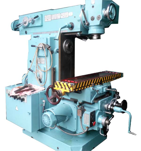
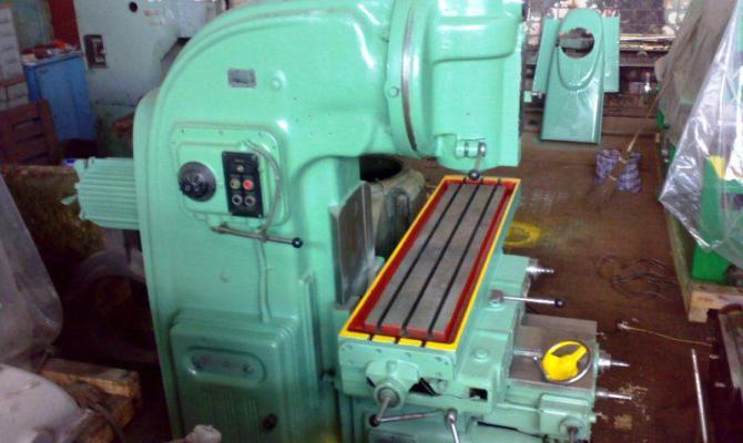
General view of the 6R81SH milling machine
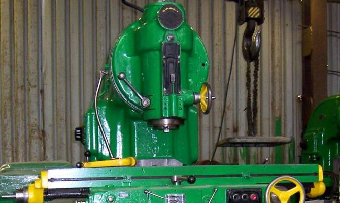
Arrangement of the components of the wide-universal console-type milling machine 6R81SH

Components of the wide-universal console-milling machine 6R81SH
- Bed - 6R81G-11.001
- Bed - 6P11-11.000
- Earring - 6R81G-11.000
- Fencing - 6P11-12.000
- Spindle drive - 6R81G-21.01
- Spindle drive - 6P11-21.01
- Gearbox - 6R81G-31.02
- Gearbox switching - 6R81G-33.01
- Feed box - 6N81G-51.02A
- Reducer - 6N81G-52.01
- Reverse box - 6N81G-53.01A
- Switching feeds - 6N81G-55.02
- Console - 6N81G-60.05
- Table - 6N81G-70.01A
- Table - 6H81-70.01
- Table and console lubrication system - 6N81G-83.02
- Table and console lubrication system - 6H81-83.02
- Cooling system - 6R81G-84.01
- Cooling system - 6R11-84.01
- Cooling system - 6R81SH-84.01
- Electrical cabinet - 6R81SH-95.02A
- Accessories - 6R81G.OP
- Accessories - 6Р11.ОП
- Accessories - 6R81SH, OP
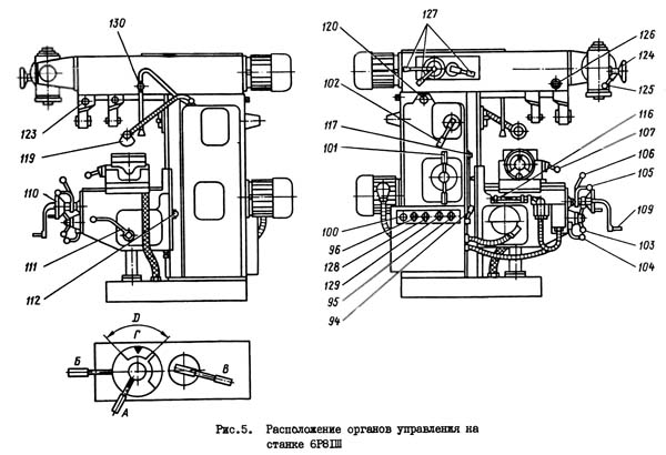
The list of controls for the 6R81Sh machine and their purpose
- Circuit breaker electrical grid
- Cooling pump switch
- Spindle rotation direction switch
- Spindle start button
- Feed start button
- General stop button
- Spindle push button
- Spindle speed shift knob
- Spindle busting shift knob
- Table feed switching handle
- Lever for switching over the feed box
- Handle for engaging mechanical vertical feed
- Handle for engaging mechanical cross feed
- Handle for engaging mechanical longitudinal feed
- Handwheel for manual longitudinal movement of the table
- Handle for manual vertical movement of the table
- Handwheel for manual transverse movement of the table
- Knob for rapid traverse in all directions
- Handle for fixing the table from vertical movement
- Handle for fixing the table against longitudinal movement
- Handle for fixing the table from lateral movement
- Stops for turning off the longitudinal mechanical movement of the table
- Stops for turning off the transverse movement of the table
- Stops for turning off the vertical movement of the table
- Handle of the drive of the manual pump of lubrication
- Local lighting switch
- Trunk displacement square
- Square for securing the trunk
- Screws and nuts for securing the upper slide from turning (for the 6P81 machine)
- Earring fastening nut
- Handwheel for moving the quill
- Quill clamping handle
- Head rotation square
- The handle for switching the speeds of the rotary spindle of the slider
- Swivel spindle rotation direction switch
- Switch for selecting the operation of the spindles (horizontal, rotary or both together)
- Handwheel for switching on and regulating the coolant supply
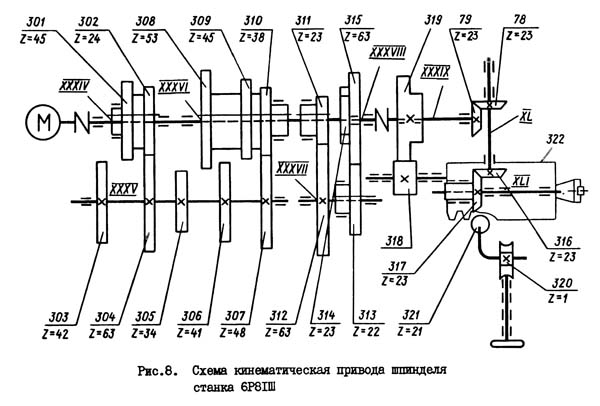
Kinematic diagram of the spindle drive of the machine 6R81SH
Slider of the machine 6R81SH
The slider is installed on the horizontal guides of the bed (instead of the trunk). The positioning movement of the slider is carried out using a rack and pinion gear per square 120 of the shaft (see Figure 5), counting the amount of movement along a ruler.
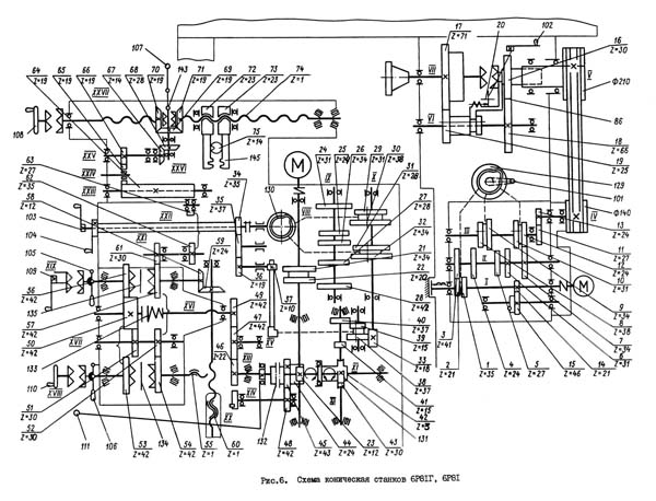
Five shafts of the rotary spindle speed box are mounted in the bores of the slider body. Shaft XXXIV (see Figure 8) is connected by an elastic coupling to the shaft of a flanged electric motor, mounted on the end of the slide. From shaft XXXIV, rotation is transmitted sequentially to shafts XXXV, XXXVI and further to shaft XXXVIII (Fig. 16) either directly by clutching the gear clutch 3II-3I4, or through enumeration of 311-312 and 313-314.
Gear shifting is achieved by means of three handles mounted in the slider cover.
Machine spindle drive 6R81SH
The rotation of the spindle is transmitted from the gearbox by a V-belt transmission, which is located in the rear cavity of the bed under the cover. From the pulley, coaxial with the spindle, the rotation of the latter is communicated either by direct connection of their cam clutch or through two gear drives 16-18 and 19-17 (Fig. 9)
The spindle is supported by rolling bearings: two angular contact bearings in front and one ball bearing in the rear support.
Adjustment of the clearance in the bearings of the front support is possible only when the spindle is completely disassembled - section "Machine tool adjustment").
Gearbox of machine speeds 6R81SH
The gearbox with an electric motor on the body is attached to the frame with a flange. At the same time, its body enters the cavity of the bed, filled with lubricating oil. An eccentric driven plunger lubrication pump is installed on the housing. right side the frame has a window with a cover.
Gear shifting in the box is made from cam 129 (see Figure 6) with curved grooves at the ends. The shaft of the cam is connected by a clutch to the shaft of the scale and shift knobs 101 located outside the frame. The sleeve is freely removed from the cam shaft when the shift cover is detached from the bed.
When disassembling the gearbox, the position of the cam and the position of the speed scale should be noted in order to restore their correct relationship during assembly.
Gearbox. Reducer of the machine 6R81SH
The cases of the feed box and the gearbox are screwed together into a single unit, after which they are installed in the console cavity on the left. To the right of the console, through a window with a cover, protrudes the gearbox shaft with a handle that includes a rapid traverse clutch.
The output gear wheel of the reducer 47 (Fig. 10.11) meshes with the gear wheel 49 of the reverse box.
The switching of sliding gears in the feed box is carried out in the same way as in the gear box by cam 130 (see Figure 6).
Its shaft is engaged with the scale and the shift handle 103 (see Figure 6) of the unit 55 (see Figure 11) of the console mounted in front.
Assembly 55 is freely removable after removing the mounting screws. Do not forget to note the relationship between the feed scale and the position of the cam in the box during disassembly, in order to then correctly assemble the switch.
Reverse box for machine 6R81SH
The mechanism of the reverse box receives rotation from the gearbox and transmits rotation to the lead screws of the longitudinal, transverse and vertical movements of the table through a safety clutch. Turning on the rotation of one or another lead screw, in the forward and reverse directions, is performed by cam couplings using handles 105, 106, 107 (see Fig. 6 and II).
For manual movements of the table, the handle 109 and the handwheel 110 are used, which are freely mounted on the shafts, and at the time of use they interlock with the shafts using cam couplings.
In the reverse box, a lock is provided to prevent the start of the mechanical feed, if the handle 109 and the handwheel 110 are not disengaged from the shafts.
The blocking is provided by balls embedded in the radial holes of the shafts under the hubs of the handle 109 and handwheel 110.
When removing the latter, the balls may fall out, it is necessary to install them in place during assembly.
When installing the reverse box in the console, the following elements should be connected:
- insert the end of shaft XIX (see Figure 6) with a key into the hole with bevel gear 58;
- interlock gears 57 and 49 with wheels 61 and 47;
- screw the screw XVIII into the nut 55 for transverse movement.
Machine console 6R81SH
The console contains the feed mechanism assemblies described above.
The screw for the transverse movement of the table is supported in the reverse box and goes out of the console through the hole.
Directly, bevel gears and a screw for vertical movement of the table are installed in the holes of the console body.
The cogwheel 63 is placed in the window of a special plug, fitted into the hole on top of the console so that the teeth protrude above the surface of the guides.
Machine table 6R81SH
In the lower part of the table slide there is a gear wheel 64 (see Figures 6 and 13), which is engaged with the gear wheel of the console 63. Due to the large length of the gear wheel 64, engagement is maintained during the entire transverse movement of the table and rotation is transmitted to the longitudinal screw of the table.
Rotation of the longitudinal movement screw is carried out by bevel gears 70 and 71 with cams at the ends. Between the bevel wheels is a bushing with a key on the inside and a cam clutch 143 on the outside. The cam clutch is turned on in one direction or another by the handle 107, which ensures the movement of the table to the right and left.
The nut of the screw for the longitudinal movement of the table is equipped with an automatic gap sampling device. The nut consists of two parts, resting with collars (through ball thrust bearings) on the ends of the bracket carrying them.
On the outer cylindrical surface of both half-nuts, teeth are cut, which are interlocked with the racks 145.
The racks, in turn, are connected to each other by a gear 75 and are limited in their movement in the direction from the bed by screws. These screws with lock nuts are visible from the front of the slide.
During climb milling, the feed force on the screw is directed in the direction opposite to the movement of the table. It causes friction in the turns of the nut, which is pressed against the bracket. Due to the frictional force, the nut rotates with the screw at a certain angle. Due to the connection with their rack and pinion system, the same turn is made by the second half-nut, but in the opposite direction.
Thus, both half-nuts are screwed onto the screw and, resting on the collars against the thrust bearings, as if stretching the screw, the gap in the turns is selected at this time. When milling against the feed, the direction of the thread force does not have the effect described above and the thread clearance remains.
Electrical diagram of the 6R81SH milling machine

6P81SH The machine is console-milling broadly universal. Video clip.
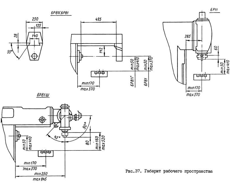
Technical characteristics of the machine 6Р81Ш
| Parameter name | 6P81 | 6R81G | 6R81SH |
|---|---|---|---|
| The main parameters of the machine | |||
| Accuracy class according to GOST 8-71 and GOST 8-82 | N | N | P |
| Dimensions of the working surface of the table (length x width), mm | 1000 x 250 | 1000 x 250 | 1000 x 250 |
| The smallest and largest distance from the end of the spindle to the table | - | - | - |
| The smallest and largest distance from the spindle axis to the table | 50..370 | 50..400 | 50..400 |
| Distance from the spindle axis to the trunk, mm | 142 | 142 | 142 |
| Distance from the vertical spindle axis to the rack guides, mm | - | - | 245..845 |
| Desktop | |||
| Number of T-slots Dimensions of T-slots | 3 | 3 | 3 |
| The greatest longitudinal movement of the table (X-axis), mm | 630 | 630 | 630 |
| The greatest movement of the table transverse (Y-axis), mm | 200 | 200 | 200 |
| Maximum vertical movement of the table (Z-axis), mm | 320 | 350 | 350 |
| The greatest angle of rotation of the table, degrees | ± 45 | No | No |
| The price of one division of the table rotation scale, degrees | 1 | No | No |
| Moving the table by one division of the limb (longitudinal, transverse), mm | 0,05 | 0,05 | 0,05 |
| Moving the table by one division of the limb (vertical), mm | 0,025 | 0,025 | 0,025 |
| Moving the table for one revolution of the limb longitudinal and transverse, mm | 6 | 6 | 6 |
| Moving the table for one revolution of the dial vertical, mm | 3 | 3 | 3 |
| Spindle | |||
| Spindle speed, rpm | 31,5..1600 | 31,5..1600 | 31,5..1600 |
| Number of spindle speeds | 18 | 18 | 18 |
| Spindle end sketch | 45 GOST 836-72 | 45 GOST 836-72 | 45 GOST 836-72 |
| Spindle taper | 45 | 45 | 45 |
| Swivel spindle taper | - | - | 40 |
| Machine mechanics | |||
| Table speed longitudinal and transverse, mm / min | 3150 | 3150 | 3150 |
| Vertical table speed, mm / min | 1050 | 1050 | 1050 |
| Number of stages of working table feeds | 16 | 16 | 16 |
| Limits of working feeds. Longitudinal and transverse, mm / min | 25..800 | 25..800 | 25..800 |
| Limits of working feeds. Vertical, mm / min | 8,3..266,7 | 8,3..266,7 | 8,3..266,7 |
| Switching feed stops (longitudinal, transverse, vertical) | there is | there is | there is |
| Manual and mechanical feed lock (longitudinal) | No | No | No |
| Blocking of manual and mechanical feed (transverse, vertical) | there is | there is | there is |
| Spindle braking (clutch) | there is | there is | there is |
| Overload protection (ball pair) | there is | there is | there is |
| Drive unit | |||
| Main drive electric motor, kW | 5,5 | 5,5 | 5,5 |
| Feed drive electric motor, kW | 1,5 | 1,5 | 1,5 |
| Electric Coolant Pump Type | X14-22M | X14-22M | X14-22M |
| Coolant electric pump, kW | 0,12 | 0,12 | 0,12 |
| Coolant pump capacity, l / min |
Milling machines (FS) are very actively used in various metalworking enterprises. Such units can be specialized or general purpose... In this article, we will look at and briefly describe all the popular types of milling machines.
1 Classification of milling units and their marking
In the Soviet Union, each machine was assigned a special number. This practice continues now.
Milling units are included in the sixth group of metal-cutting machine-tool equipment, therefore their marking code always begins with the number 6.
The next character in the number is a letter that gives information about the modification or modernization of the machine. In some cases, this letter (or a combination of several letters) is placed at the end of the marking. If you see the letter W in the code, this means that we have a universal unit in front of us, P - an installation of increased accuracy, F - a CNC machine ( program control), P - equipment of increased accuracy, M - modernized, R - new (modified).
The second digit after the letter or immediately after the first number indicates the specific type of FS. There are several of them. Number 1 "hides" console milling units. They can be vertical-milling and horizontal-milling of two types - universal (equipped with a table with a rotary structure), conventional (non-rotating work surface). Widely versatile console machine, which is available in any modern industrial enterprise, is also included in the first group of the described machine tool equipment.
The number 2 indicates that we have a consoleless vertical milling unit in front of us, 3 - bed milling machine(with one or two posts in the structure), 4 - installation continuous action(drum or carousel), 5 - copy-milling (production or manual), 6 and 7 - key and face milling machine, respectively. Specialized FS are marked with the number 8. Their purpose may be different, machines of this group are used to perform any special work.
The third digit (0-4) in the marking describes geometric parameters unit. In some FS models, there is also a fourth digit, which also serves to indicate the size of the equipment:
- 0 - working table 20 by 80 cm;
- 1 - 25 x 100 cm;
- 2 - 32 by 125 cm;
- 3 - 40 by 160 cm;
- 4 - 50 by 200 cm.
Knowing the described classification of milling machines, it is not difficult to determine the purpose of specific equipment, be it a universal, horizontal milling, manual or other unit that has been modernized or equipped with a CNC system.
2 The most common milling machines
Console installations are in the greatest demand. Their feature is the location of the sled and the working surface on the console, which is able to move when performing metalworking operations in three directions (vertically, longitudinally, transversely). Such machines serve as the basis for the production of various milling equipment... On their basis, CNC machines, engraving and copy-milling units are produced. Note that almost any universal aggregate is cantilever. It is used to process products from all kinds of materials:
- hard plastics;
- non-ferrous metals and common ferrous;
To perform such work, a console-milling machine is equipped with shaped, end, cylindrical and other devices.

A versatile machine with a cantilever design is often equipped with a rotary table and special dividing heads. They are used for milling cylindrical (oblique and spur) gears and for making grooves (helical) on reamers, drills and other cutting tools (manual mode). As a rule, a highly versatile unit is used in the production of single items in repair and experimental departments of large factories. It can be equipped with CNC.
Popular console hardware models:
- (universal);
- 6R81SH (wide-universal);
- 6R81G (horizontal milling);
- 6P11 (vertical).
Such units are produced by the Dmitrovsky plant (it also previously manufactured equipment of the H-series - 6H11, 6H81). Their design is the same, they all have approximately identical gear boxes, consoles, reverse gears and other units.

Console machines of the M and P series, in the production of which the Lithuanian plant Zalgiris specializes, are intended for milling small-sized steel and metal parts... The wide-universal unit 6P80SH, horizontal milling 6M80G, copying (with CNC) 6P10K are in great demand by Russian enterprises. They can be seen in many modern factories.
Pay attention - the versatile unit of the P series is considered to be more efficient in operation. Compared to cantilever machines of other models, it has greater productivity and operational reliability. It can be equipped with a CNC system and set up for automatic work cycles.
3 Consoleless and longitudinal milling equipment
Vertical and horizontal milling units without a console have their own purpose. They are used for milling large-sized workpieces. The table and slide in such machines make working movements along the guides of the bed, which is mounted on a solid foundation. Due to this, the equipment guarantees unique processing accuracy and structural rigidity, which is important when processing large parts.
In horizontal and vertical milling equipment that does not have a console, the gearbox and the spindle head are one unit. He moves along the guides of the posts. In this case, the sleeve with the head is allowed to move a certain distance along the axis when it is necessary to mount the working tool to a given size.
To work with large metal workpieces, a longitudinal milling machine is often used. Such equipment can have two or one rack and several spindles (most often four). The longitudinal milling unit usually includes two beams and two stands. The milling rotary heads (they are located horizontally) and the traverse move along the guides of the latter.
The working operation on these installations is carried out according to different schemes:
- when feeding heads and a stationary working surface;
- with stationary heads and moving surfaces;
- when moving heads and table together.
Common non-cantilever and longitudinal milling units include the following equipment: 6A59 (vertical for boring, drilling and milling steel products with high-speed tools), 654, 659 and 656 (produced at the Ulyanovsk plant). Now they are trying to replace this equipment with foreign horizontal milling units without a console from DEKA, JET. However, the old installations, released several decades ago, demonstrate excellent performance.
4 Other types of milling equipment
A drum or carousel milling machine is classified as a "continuously operating" unit. Continuity is understood as the fact that the equipment does not need to be stopped during assembly and fixation of parts for processing, as well as when they are removed after the completion of milling.
Drum set is easy to distinguish from any other, as it has a special drum with eight or four edges. It is installed with the axis of rotation located horizontally on a shaft, which, together with the drum, makes a uniform rotation, transmitted by the drive of the machine. Fixation of products for milling is carried out in fixing devices. There is also a feed box in the design of such a FS, which regulates the speed with which the drum rotates.

Drum-carousel equipment has milling heads (they are mounted on racks). They can be fixed in all required positions, which makes it possible to process the workpiece from two planes at once. Such machines have found application in the mass and large-scale production of metal parts.
Carousel FS is a reliable frame on which stands (vertical) are installed, connected to each other by a horizontal plate. It is placed at the top of the structure, thereby creating a frame closed system... The spindle heads are mounted on a traverse. She stands on the racks. The advantage of carousel-milling equipment is to increase the productivity of the milling operation by combining the auxiliary time with the processing time of the workpiece.
Turbine blades with complex molds and similar blanks are milled with an end tool on special copy-milling units. They are often equipped with a CNC, and can be manufactured with or without a console. For home use and small businesses, you can purchase a manual copy machine... It is often equipped with a CNC system that simplifies the milling procedure. On such machines, volumetric or contour milling is performed.
Manual FS is purchased by home craftsmen and small manufacturing firms engaged in the manufacture of frames for loggias and balconies, metal entrance doors and other "little things". The cost of such equipment is quite reasonable. Not difficult to buy cheap manual machine made in China to perform standard milling operations in their garage. Let's note one important fact... A modern manual FS, as a rule, is equipped with a CNC complex. For this reason, the effectiveness of its use, even by poorly trained specialists, is very high.
Send your good work in the knowledge base is simple. Use the form below
Students, graduate students, young scientists who use the knowledge base in their studies and work will be very grateful to you.
Posted on http://www.allbest.ru/
Introduction
1. General part
1.1 Purpose and arrangement of the workshop
2. Special part
2.1 Purpose and device of the console-milling universal machine 6E80SH
2.3 Lubrication of the console-milling universal machine model 6E80SH
3. Organization of production
3.1 Technical documentation for the overhaul of a wide-universal console-milling machine model 6E80SH
3.2 List of auxiliary equipment, fixtures and tools for overhaul of the console-milling universal machine model 6E80SH
4. The economic part
4.1 Time limits for overhaul console-milling universal machine model 6E80SH
4.2 Tariff rates in the workshop
5. Measures for safety and fire prevention
5.1 Occupational safety at the site
5.2 Safety precautions
5.3 Industrial sanitation
5.4 Fire protection
5.5 Environmental protection
Bibliography
Introduction
ArcelorMittal is the largest metallurgical company in the world, controlling 10% of the world steel market at the end of 2008. Registered in Luxembourg.
It was formed in 2006 through the merger of the Luxembourg company Arcelor and the Indian Mittal Steel, owned by the Indian businessman Lakshmi Mittal.
After the merger, the company's production capacity amounted to 120 million tons per year. The development goal was announced to increase the capacity over the next five years to 150 million tons. The economic crisis led to the postponement of the projects being implemented from 2011-2012 to 2014.
ArcelorMittal Temirtau Joint Stock Company is the largest enterprise in the mining and metallurgical sector of the Republic of Kazakhstan and is an integrated mining and metallurgical complex with its own coal, iron ore and energy base.
ArcelorMittal Temirtau JSC includes:
Steel Department;
Coal Department;
Iron Ore Department.
ArcelorMittal Temirtau JSC specializes in the production of flat and long products, including those with polymer, zinc and aluminum coatings, and also produces sinter, iron ore and coal concentrate, coke, pig iron, steel, including continuously cast slabs, strips, spars strip, electrowelded pipes and related products of blast-furnace and coke-chemical industries.
ArcelorMittal Temirtau JSC is a socially oriented company. The balance of the enterprise includes rest houses, sanatoriums, children's summer camps recreation, sports complexes and medical institutions. The company is a supplier utilities(hot and cold water, heating, electricity) residents of Temirtau.
technological cantilever milling machine
1. General part
1.1 Purpose and arrangement of the workshop
Shop passport number 31
The workshop was designed by the Karaganda branch of Gipromez in 1957, built and commissioned by the Kazmetallurgstroy trust in September 1970 (without the administrative building).
The shop was intended for repairs of sinter-blast furnace equipment, steel-making plants and foundries. In October 1971, the workshop was reorganized in connection with the creation of an independent structural unit TsRMO-1.
TsRMO-2 is intended for repairs of steel-making shops equipment, manufacture and restoration of spare parts, blast furnace tuyeres, converter tuyeres heads, manufacture and restoration of steel-pouring ladle stop rods.
The shop consists of two repair sections (open-hearth and converter) and a mechanical repair shop.
The workshop is located in a two-span building 96 meters long and 18 meters wide, with a total area of 3460.
Intrashop transportation of goods is carried out by three electric bridge cranes with a lifting capacity of 5 tons, two cranes with a lifting capacity of 15/3 tons, an electric pallet truck with a lifting capacity of 10 tons, two electric cars and two electric trucks.
External cargo turnover is carried out by rail and road transport.
The workshop has three vehicle entrances and an 18 m long railway access track. All workshop entrances are equipped with air curtains.
The workshop is heated by 5 STD-300 units.
The project provides for:
1. Removal of products from 1 total area of the workshop - 0.68 t / year
2. Removal of products from one main machine - 88.5 t / year
3. Release of products per one machine operator - 54.5 t / year
4. Production of products per worker - 22.6 tons / year.
Productive capacity
|
Name |
Annual release |
||||
|
According to the project |
In fact, on 1.01.72 g. |
||||
|
Spare parts machining |
|||||
|
Mechanical processing of remanufactured spare parts |
|||||
|
Stopper rod machining |
|||||
|
Tuyere repair |
|||||
|
Repair and installation work |
TECHNOLOGICAL PROCESS.
The technological process of processing spare parts is individual and small-scale. Casting, forgings and section metal for the manufacture of spare parts are supplied to the shop from the warehouses of the OTC and procurement shops of the chief mechanic's office. Repair technology consists in assembling and revising units during preparation for repairs, replacing units, individual parts and revising units during the period of repair.
The workshop is set to operate in two shifts, with a duration of 8.25 hours for a five-day working week with two days off.
1.2 Purpose and brief technical specifications main equipment
CHARACTERISTICS OF SITES AND REPAIR AND MECHANICAL WORKSHOP.
The equipment repair section of the open-hearth shop - performs scheduled preventive maintenance of equipment in accordance with the approved schedules in the open-hearth, refractory and train preparation shop.
The site is located in the open-hearth shop.
The site consists of 7 teams (60 people) of repair mechanics, electric gas welders and cutters.
The section for the repair of equipment of the converter shop - performs scheduled preventive repairs of equipment in accordance with the approved schedules in the converter and pile-up shops.
The site is located in the built-in room of the main building of the converter shop on area 60, at 23rd level.
The site consists of 7 teams (62 people) of repair mechanics, electric gas welders and cutters.
Mechanical repair workshop.
Posted in production building workshop. The mechanical repair workshop includes:
A) mechanical department;
B) fitting and assembly department;
B) forging and welding and procurement department;
D) department of manufacturing and restoration of locking rods;
E) electromechanical service.
The mechanical compartment is designed for mechanical processing spare parts. Located in the AB bay on an area of 48. The number of machine tools is set in the department, based on the complexity of processing one ton of products - 90 machine-hours.
The locksmith and assembly department is intended for the assembly and revision of equipment units of the steel-making shops of the plant. The department is located in the aisle AB and BV on area 972. The department consists of 2 brigades (10 people) of locksmiths.
The forging, welding and procurement department is intended for the manufacture of small forgings and tool blanks, cutting blanks from rolled products of various profiles and the manufacture of copper tuyeres of the open-hearth and converter shops. The department with a metal warehouse is located in the AB bay on the area 648.
The department for the manufacture and restoration of stopping rods is intended for the production of stopping rods for steel-pouring ladles. The work is carried out on a production line with a capacity of 1600 tons. Stop rods per year.
Currently, the project of the department is being revised in order to improve the technological process of manufacturing stopper stubble.
The electromechanical service is designed to carry out preventive maintenance and troubleshoot equipment in a mechanical workshop. The service is located in the BV bay in a built-in room with an area of 180. The service consists of 4 electricians and 6 locksmiths.
The material warehouse is located in the BV bay in a built-in room with an area of 24. The warehouse is intended for storage of material and technical values. Work on the transportation of goods in the warehouse is done manually.
The spare parts warehouse is located in the BV bay on area 24, fenced off with a metal mesh. The warehouse is served by an electric forklift with a lifting capacity of 5 tons.
ELECTRIC SUPPLY OF THE SHOP.
The power supply of the workshop is carried out from 12 substations with a 10 kilovolt cable. A step-down transformer of 1000 kVA, 10 / 0.4 sq.
General electric power workshop - 660 kW.
Including power - 440 kW;
crane - 184 kW;
electric furnace - 8 kW;
electric welding - 28 kW.
Intrashop networks are connected to the NTP 0.4 kV, the wiring is made in pipes with an APR-type wire. All ShR and ShchU boards are equipped with A3124 and A3131 submachine guns.
The workshop is illuminated with GE-50 lamps in the amount of 87 lamps. The total electrical power of the lamps is 43.5 kW.
Intrashop networks
|
Name |
Place of insertion |
Intrashop network |
||||
|
diameter mm |
number |
|||||
|
Gas pipeline |
General plant highway |
|||||
|
Oxygen pipe |
||||||
|
Steam line |
||||||
|
Compressed air line |
||||||
|
Hot water pipeline |
||||||
|
Potable water supply |
||||||
|
Process water pipeline |
AUTOMOTIVE TRANSPORT
For intrashop and in-plant transportation in the workshop there are 2 electric forklifts EP-301 with a universal forks with a lifting capacity of 3 tons and 2 electric cars EK-2 with a lifting capacity of 2 tons.
SANITARY AND HOUSEHOLD CONDITIONS.
The administrative building of the workshop is under construction. The personnel of the repair and assembly teams are temporarily housed in the administrative building of the open-hearth and converter shops.
Technical characteristics of the equipment
|
Name, type, model, manufacturer |
Technical specifications |
|||
|
MECHANICAL DEPARTMENT |
||||
|
Console-type milling machine 6M12P (Gorky machine-tool plant) |
Distance from spindle nose to table: The smallest is 30 mm; The largest is 400 mm. The size of the working surface of the table - 1250Ch320 mm. Largest table movements: Longitudinal - 700 mm; Transverse - 260 mm; Vertical - 370 mm. Internal spindle taper - B 3 The greatest angle of rotation of the spindle head is ± 45 °. The greatest axial movement of the spindle is 70 mm. The limits of the spindle rotation speed are 31.5 h1600 rpm. |
|||
|
Widely universal console milling machine 6M82SH |
The dimensions of the working surface of the table are 125X320 mm. Mandrel diameter - 32 mm; 50 mm. The number of spindles is 2. Spindle taper: Horizontal - №3. Rotary and overhead heads - No. 2. Spindle speed limits: Horizontal 31.5h1600 rpm; Swivel head 90-1400 rpm. Limits of longitudinal and transverse table feed: 25 ÷ 1250 mm / min. The range of vertical table feeds is 8.3-416.6 mm. Longitudinal table travel - 700 mm. The transverse course of the table is 240 m. Vertical table travel - 420 mm. Rotation of the milling head in the transverse plane of the table - 45-90 °. The maximum weight of the workpiece is 250 kg. |
|||
|
Hydraulic cross-planer 7M37 (Gomel machine-tool plant) |
Slider stroke - 150x100 mm. Table dimensions - 560Ch1000 mm The greatest distance between the plane of the table and the slider is 500 mm. The largest horizontal movement of the table is 800 mm. Slider speed limits - 3h48 m / min. The greatest angle of rotation of the incisor slide is ± 60 °. |
|||
|
Hydraulic slotting machine 7M430 (Gomel machine-tool plant). |
Chisel stroke - 320 mm Table rotation - 360 ° Table diameter - 700 mm The greatest movement of the table: Longitudinal - 600 mm Transverse - 300 mm. The cutter speed limits are 3 hours 24 m / min. |
|||
|
Planer 7210 (Minsk Machine-Tool Plant) |
The distance between the table surface and the cross member is 1000 mm. Distance between posts - 1100 mm Table dimensions: 3000X900 mm. Table stroke length: The largest - 3200 mm; The smallest is 700 mm. Number of calipers: On the crossbar - 2; On the counter - 1. The horizontal movement of the calipers along the cross member is 1500 mm. The vertical movement of the support along the rack is 900 mm. Working speed of the table - 4h90 m / min. Return speed of the table - 12h90 m / min. |
|||
|
Carousel machine 1531 (Krasnodar machine-tool plant). |
Faceplate diameter - 1150 mm Faceplate revolutions - 6.3 h315 rpm. The angle of inclination of the vertical support is ± 45 °. Lift height of the vertical support - 550 mm. Cross slide travel - 630 mm Caliper feed - 0.05 ÷ 12.5 mm / rev. |
|||
|
Horizontal boring machine 2620V (Leningrad machine-tool association named after Sverdlov). |
Spindle diameter - 90 mm. Spindle speed - 12.5 h2000 rpm. Rotational speeds of the faceplate - 8h200 rpm. Internal taper of the spindle - Morse code No. 5. The dimensions of the working surface of the table are 1120X1300 mm. Largest displacement: Vertical headstock - 1000 mm; Spindle lengthwise - 710 mm; Tables across - 1000 mm; Table lengthwise - 1090 mm; Radial face plate support - 170 mm. The largest diameter of the bore hole: Spindle - 330 mm; Caliper - 600mm. |
|||
|
Radial drilling machine 2H55 (Odessa machine-tool plant). |
The largest drilling diameter is 50mm. Morse taper - # 5. The greatest axial movement of the spindle is 350 mm. Spindle overhang - 410h1600 mm. Spindle speed - 20-2000 rpm |
|||
|
Screw-cutting lathe 1E61M (Izhevsk machine-tool plant) |
Center height - 170 mm. The hole in the spindle is 32 mm. Above the support - 183 mm; Above the bed - 320 mm. |
|||
|
Screw-cutting lathe 1K62 (Machine-tool plant named after Efremov, Moscow) |
Center height - 215 mm. Spindle bore - 38 mm The largest diameter of the workpiece: Above the support - 260 mm; Above the bed - 400 mm. |
|||
|
Screw-cutting lathe 1625 (Machine-tool plant named after Efremov, Moscow) |
The distance between the centers is 1400 mm. Center height - 215 mm. The hole in the spindle is 47 mm. The largest diameter of the workpiece: Above the support - 260 mm; Above the bed - 400 mm. |
|||
|
Screw-cutting lathe 1A616 (Kuibyshev machine-tool plant). |
Distance between centers - 710 mm. Center height - 170 mm. The hole in the spindle is 32 mm. The largest diameter of the workpiece: Above the support - 188 mm; Above the bed - 320 mm. |
|||
|
Screw-cutting lathe 163 (Tbilisi Machine-Tool Plant) |
The distance between the centers is 1400 mm. Center height - 265 mm. The hole in the spindle is 65 mm. The largest diameter of the workpiece: Above the support - 350 mm; Above the bed - 630 mm. |
|||
|
Screw-cutting lathe 9Н14С3 (Tbilisi Machine-Tool Plant) |
Distance between centers - 710 mm. Center height - 265 mm. The hole in the spindle is 65 mm. The largest diameter of the workpiece: Above the support - 350 mm; Above the bed - 630 mm. |
|||
|
Screw-cutting lathe 165 (Ryazan machine-tool plant) |
The distance between the centers is 2800-5000 mm. Center height - 500 mm. The hole in the spindle is 80 mm. The largest diameter of the workpiece: Above the support - 650 mm; Above the bed - 1000 mm. Spindle speed - 5h500 rpm. |
|||
|
Cylindrical grinding machine ZA164A (Plant "Kommunar", Lubny, Poltava region) |
The distance between the centers is 2800 mm. The largest diameter of the product is 400 mm. The greatest weight of the product is 250 kg. Largest circle dimensions: Outer diameter - 750 mm; Internal diameter - 40 mm; Width - 70 mm. |
|||
|
ASSEMBLY DEPARTMENT. |
||||
|
Horizontal hydraulic press P983 (Odessa plant of presses). |
Effort - 315 t. The fluid pressure in the network is 200 kg / cm². The largest stroke of the plunger is 850 mm. The maximum diameter of the pressed-on product is 1500 mm. Working fluid is oil. Distance from the end of the plunger to the end of the movable thrust beam: Maximum - 2900 mm; Minimum - 900 mm; Working - 2500 mm. |
|||
|
Single-column hydraulic press P6320 (Orenburg plant "Metallist"). |
Effort - 10 tons. The fluid pressure in the network is 160 kg / cm². The stroke of the rod is 400 mm. Table dimensions - 380X500 mm. |
|||
|
Rough grinding machine ZM-634 (Jalal-Abad repair plant) |
Number of circles - 2 The dimensions of the circles - 400Ch40Ch203 mm Spindle speed - 1420 rpm. Distance between centers - 700 mm Center height - 830 mm |
|||
|
Vertical drilling machine 2A135 (Plant named after Lenin, Sterlitomak). |
The maximum drilling diameter is 35 mm. Spindle taper - Morse code No. 4. Spindle axis overhang - 300 mm. Spindle stroke - 225 mm. Headstock stroke - 200 mm. Spindle speed - 68-1100 rpm. Feed range - 0.12 to 1.6 mm / rev. |
|||
|
Forging and welding and procurement department. |
||||
|
Pneumatic forging hammer М415А (Voronezh plant KPO). |
The weight of the feeding parts is 400 kg. The number of beats per minute - 130 The effective kinetic energy of the feeding parts is 950 gm. The distance from the axis of the woman to the bed is 520 mm. The distance from the striker's mirror to the woman is 530. The dimensions of the striker mirror are 265x100 mm. Optimal forged section of the workpiece: Square - 100 mm; Round - 115 mm. |
|||
|
Cut-off hacksaw 872 (Krasnodar Experimental Plant named after Kalinin). |
The length of the saw frame stroke is 140х180 mm. Blade length - 450 mm The number of strokes of the saw frame per min - 85-110. |
|||
|
Cut-off milling machine 8В66 (Minsk Machine-Tool Plant) |
Speed saw blade in min. - 3.3h25.5 Saw blade diameter - 710 mm. Cutting speed - 7.4h57 m / min. The largest diameter of the workpiece to be cut is 230 mm. |
|||
|
Welding converter PSO-300 |
Current regulation limits: |
|||
|
Welding transformer TD-500 (plant p / I M-5293) |
||||
|
Forge forge |
Manufactured by the workshop. |
|||
|
Heating chamber furnace |
The area of the hearth is 0.66 m2. Fuel: coke oven gas. |
|||
|
ELECTRO-MECHANICAL SERVICE. |
||||
|
Vertical drilling machine 2A125 (Mechanical plant, Kabanye settlement, Luhansk region). |
The largest drilling diameter is 25 mm. Spindle stroke - 200 mm. Spindle speed in min. - 165h2130. The largest movement of the table is 400 mm. Table dimensions - 350X400 mm. |
|||
|
Rough grinding machine 3M-634 (Mukachevo plant named after Kirov) |
The number of circles is 2. The dimensions of the circles are 400X40X203 mm. Spindle revolutions in min. - 700h1400. |
|||
|
Surface grinding machine 372B (Moscow Machine-Tool Plant). |
The dimensions of the processed products are 1000X300X400 mm. Table dimensions - 1000X300 mm. Circle height - 40 mm. Circle diameter: Outside - 250x350 mm; Internal - 127 m. |
|||
|
Universal sharpening machine 3659A (Vitebsk plant of sharpening machines). |
Diameter of drills to be sharpened, zinkers - 80 mm. Sharpening angles - 70 ° h140 °. The number of nibs of the sharpened tool is up to 12. Grinding wheel: Outer diameter - 200 mm; Internal - 32 m; Height up to - 70 mm. The number of revolutions of the circle in min. - 1850 |
Lifting and conveying equipment
|
Name, No., manufacturer |
Installation Location |
Technical specifications |
|||
|
Electric bridge crane No. 1 (Mechanical plant, settlement Novobureisk, Khabarovsk region). |
Forging and procurement department Mechanical department. Stopper rod manufacturing department |
Carrying capacity - 5 tons. The length of the bridge is 16.5 m. Movement speed: Crane - 73.5 m / min; Carts - 38 m / min; Ascent - 10 m / min. Lifting height - 8 m. |
|||
|
Electric bridge crane No. 3 (Machine-building plant, station Uzlovaya, Tula region). |
Fitting and assembly department |
Carrying capacity - 15/3 tons. The length of the bridge is 16.5 m. Movement speed: Crane - 49 m / min; Carts - 18 m / min; Main lift - 2.2 m / min; Auxiliary lift - 9.7 m / min. Lift height: Main - 8.5 m; Auxiliary - 8.5 m. |
|||
|
Electric bridge crane No. 4 (PTO plant, Alexandria, Kirovograd region). |
Fitting and assembly department |
Carrying capacity - 15/3 tons. The length of the bridge is 16.5 m. Movement speed: Crane - 75.3 m / min; Carts - 34.5 m / min; Main lift - 8 m / min; Auxiliary lift - 19.2 m / min. Lift height: The main one - 8 m; Auxiliary - 8 m. |
|||
|
Electric trolley (Dnepropetrovsk Metallurgical Equipment Plant). |
Between spans in axes 4-5 |
Carrying capacity - 10t; Rail kalea - 1000 mm; Bogie base - 1600 mm. Platform size - 2630x1650 mm. Travel speed - 40 m / min. Drive from the MTK-11-V electric motor, Power of 2.2 kW, 885 rpm. Push-button control. |
2. Special part
2.1 Purpose and device of the console-milling universal machine model 6E80SH
Figure 2.1.1 Console-milling universal machine model 6E80SH
Universal console-milling horizontal machine 6E80SH is designed for milling and some types of boring work on parts small size from ferrous and non-ferrous metals and plastics.
They are used in the conditions of single and serial production. The technical characteristics of the machines allow you to fully utilize the capabilities of high-speed steel tools, as well as tools equipped with carbide inserts.
The swivel milling head with a retractable quill allows milling of inclined surfaces of parts. The use of a dividing head, a rotary table, a vice expands the technical capabilities of the machine.
The machines work on the principle of milling with a rotating stationary cutter, fixed in a horizontal or vertical spindle. Movements of the table (X coordinate), slide (Y coordinate), arm (Z coordinate) are used as working or setting movements.
Using in CNC equipment allows you to process parts according to the program in automatic mode.
Design features:
The rack is the base unit on which all other units and mechanisms are mounted. The stand is rigidly connected to the slab (base). A vertical spindle head is mounted on the trunk of the machine, and suspensions for working with long mandrels are attached to the guides of the trunk.
The gearbox of the horizontal spindle is mounted in a rack. The drive of the vertical spindle is carried out by an electric motor, placed on top of the head.
The rear wall of the console is made in the form of dovetail guides. The sled moves laterally on the console and has rails for the table. A longitudinal feed screw is connected to the table. Work is possible both by the method of passing, and by the method of counter milling.
Machine composition:
Mechanism for switching the vertical movement of the table, slide, table, cooling system, electrical cabinet, mechanisms for switching the transverse movement of the table, bed, feed box, mechanism for switching feeds, mechanism for switching the rotation frequency of the horizontal spindle, gearbox and spindle, trunk with a spindle head, protective device, mechanism for switching the frequency of rotation of the vertical spindle, suspension, console.
Devices and operation of the machine and its main parts.
Governing bodies and their purpose:
Handle of manual vertical stirring table
Handwheel for manual transverse movement of the slide
Vertical feed engaging handle
Backlash sampling worm on the longitudinal screw
Handwheel for manual table movement
Table clamp
Switch "Lighting"
Spindle sleeve clamping handle
Cooling system valve
Handle for turning on the mains
Table Fast Move Button
Start button
Emergency stop button
Carriage clamping handle
Cross feed engaging handle
Console clamp handle
Feed motor switch
Cooling pump switch
Direction of rotation switch for horizontal spindle
Push button
Vertical spindle rotation direction switch
Horizontal spindle brute-force switch knob
Horizontal spindle speed shift knob
Manual movement of the trunk
Clamp to the trunk on the bed
Clamping the milling head to the trunk
Worm turning the milling head in the longitudinal plane of the table
Worm turning the milling head in the transverse plane of the table
Vertical spindle brute-force handle
Knob for switching over the pulleys of the vertical spindle
Vertical spindle speed shift knob
Handle for moving the sleeve of the vertical spindle
Longitudinal feed engaging handle
Handle for moving the feed box
Feed switch handle
Screws for clamping the slide of the machine 6T80
Stop button
Kinematic diagram.
The spindles are driven by electric motors through a V-belt transmission.
The spindles have 12 different speeds, obtained when the gear blocks move along the splined shafts. The feed wire is carried out from the electric motor through coupling sleeve, from shaft IX to the feed box. By moving the gear blocks, the feed box provides 18 different feeds, which are transmitted to the XUI shaft of the console and then, when the corresponding cam clutch is turned on, to the screws for longitudinal, transverse and vertical movement.
Accelerated movements are carried out from the electric motor through shafts IX, X, HP, XU, electromagnetic and freewheel clutches on the CL shaft of the console.
The inclusion and reversal of longitudinal, transverse, vertical feeds is performed by double-sided cam couplings.
The bed is the basic part of the machine, on which all other components and mechanisms are mounted. The stand of the bed is rigidly connected to the plate (base), which is the reservoir of the coolant.
A vertical spindle head is mounted on the trunk of the 6E80SH machine, and suspensions for working with long mandrels are attached to the guides of the trunk. The suspensions have a rolling bearing and a sliding bearing. The hangers on the machine tools are not interchangeable; to install the hangers, turn the head up.
The gearbox of the horizontal spindle is mounted in the bed. The connection to the electric motor is carried out through a V-belt transmission. Inspection and access to the gearbox - through the window of the gearshift unit on the virgin side of the bed. The drive of the vertical spindle of the machine is carried out from an electric motor brought out to the top of the head through a V-belt transmission, a roller clutch and a gearbox.
The spindle is mounted in a sliding sleeve. The spindle head of the 6E80SH machine is attached to the trunk through a clamp and has the ability to rotate in the transverse and longitudinal directions of the table. The feed drive is located in the console. In front, in the lower part of the console, there is a built-in flanged electric motor, on the left side of the console there is a feed box with a feed switching mechanism and a mechanism for activating the vertical movement of the table, on the right - a mechanism for activating the transverse movement of the table. The eighteen-speed feed box has a rapid traverse chain with a safety clutch, which excludes the possibility of damage to the feed drive during overloads.
An electromagnetic clutch and an overrunning clutch are mounted on one shaft with a safety clutch. The inclusion of fast movements of the table is carried out by the button. The feed switching mechanism consists of cam handles with profile grooves, a dial and levers for gear shifting.
Gearbox gear shifting occurs when the dial rotates around the axis and when the axis is rotated by the handle.
The vertical and transverse mechanical movements of the table are switched on by handles. The direction of movement of the handles is mnemonically linked to the direction of movement of the table.
Manual vertical movement of the table is carried out by a handle, transverse - by a handwheel.
The rear wall of the console is made in the form of dovetail guides.
The upper part of the console has rectangular guides along which the slide moves.
The sled moves laterally on the console and has rails for the table.
A longitudinal feed screw is connected to the table. The slide contains bevel gears that rotate the screw, handles and a longitudinal feed engaging mechanism.
When working with the method of passing milling, a selection of gaps between the thread of the lead screw and the nuts is provided by turning the worm.
When working with the counter milling method, the lead screw is heavily wears out. Therefore, if one work is performed on the machine for a long time, the section of the screw should be changed.
A bracket with a nut, which is attached to the body of the slide and connected to the console screw, is used to carry out the transverse feed.
Basic technical data and characteristics of the machine.
Dimensions of the table working surface (length x width), mm 200 x 800
The number of T-shaped slots of the table 3
The greatest movement of the table, mm
longitudinal 560
transverse 220
Distance from the axis of the horizontal spindle to the working surface of the table, mm
smallest 0
greatest 400
Distance from the end of the vertical spindle to the working surface of the table, mm
smallest 15
greatest 400
Angle of rotation of the spindle head, degrees
in the longitudinal plane of the table ± 45
in the transverse plane of the table (to the bed) 30
in the transverse plane of the table (from the bed) 45
The stroke of the sleeve of the spindle head, mm 70
Number of spindle speeds (horizontal / vertical) 12
Spindle speed limits, min -1
horizontal 50-2240
vertical 56-2500
Number of table feeds 18
Limits of table feed, mm / min
longitudinal and transverse 20-1000
vertical 10-500
Speed of fast movement of the table, m / min
longitudinal and transverse 3.35
vertical 1.7
Division price of table movement limbs, mm
longitudinal and transverse 0.05
vertical 0.02
The division value of the limb of the vertical spindle sleeve movement, mm 0.05
Overall dimensions of the machine (length x width x height), mm 1600x1875x2080
Machine weight (with electrical equipment), kg 1430
A tool used when machining on a machine.
The 6T80SH horizontal milling cantilever machine is distinguished by the presence of a cantilever and a horizontal arrangement of the spindle when machining flat and shaped surfaces of workpieces made of various materials... End mills and end mills can also be used.
Cylindrical cutters are used when machining planes. These cutters can be straight or helical. Helical cutters run smoothly; they are widely used in manufacturing. Straight cutters are used only for machining narrow surfaces where helical cutters are not beneficial. great influence on the cutting process. When cylindrical milling cutters with helical teeth operate, axial forces arise, which at an angle of inclination of the OMEGA tooth = 30 -: - 45 * reach a significant value. Therefore, cylindrical double cutters are used, in which screw cutting teeth have a different direction of inclination. This allows you to balance the axial forces acting on the cutters during the cutting process. At the junction of the cutters, it is envisaged to overlap the cutting edges of one cutter with the cutting edges of the other. Cylindrical cutters are made of high speed steel and are equipped with carbide inserts, flat and helical.
Corner cutters are used when milling corner slots and ramps. Single corner cutters have cutting edges located on conical surface and the end. Double corner cutters have cutting edges located on two adjacent tapered surfaces.
Corner cutters are widely used in the tool making for milling chip grooves. various instruments... In the process of working with single-angle milling cutters, axial cutting forces arise, since the metal of the workpiece is cut off mainly by cutting edges located on the conical surface. In double-corner cutters, the axial forces arising from the operation of two adjacent corner edges of the tooth somewhat compensate each other, and when symmetrical double-corner cutters are working, they are mutually balanced. Therefore, double corner cutters run more smoothly. Small angle mills are available with cylindrical or taper shank end mills.
Shaped cutters are widely used in the processing of a variety of shaped surfaces. The advantages of using routers are especially pronounced when machining workpieces with a large length-to-width ratio of the surfaces to be milled. Short shaped surfaces in high-volume production are best handled by pulling. Shaped cutters, according to the design of the teeth, are divided into cutters with undercut teeth and cutters with sharp-pointed (sharpened) teeth.
End mills are widely used when machining planes on vertical milling machines. Their axis is set perpendicular to the machined plane of the part. Unlike cylindrical cutters, where all points of the cutting edges are profiling and form a machined surface, in end mills, only the tops of the cutting edges of the teeth are profiling. End cutting edges are auxiliary. Main job cutting is performed by side cutting edges located on the outer surface.
End mills are used for processing deep grooves in body parts, contour grooves, ledges, mutually perpendicular planes. End mills in the machine spindle are mounted with a tapered or cylindrical shank. In these cutters, the main cutting work is performed by the main cutting edges located on the cylindrical surface, and the auxiliary end cutting edges only clean the bottom of the groove. These cutters are usually made with helical or oblique teeth. The angle of inclination of the teeth reaches 30-45 *. The diameter of the end mills is chosen to be smaller (up to 0.1 mm) of the groove width, since the groove breaking is observed during milling.
Shell end mills are mounted using a transition flange. The mandrel in the spindle cone is attached with a cleaning rod. A transition flange is put on the mandrel neck and a cutter, which is fastened with a screw. The cutters, which have a keyway in the hole, are mounted on a mandrel with a shoulder, which has grooves for the spindle pins.
Face mills and end mills with a Morse taper shank are attached to the spindle taper by means of an adapter sleeve.
Cutters large diameter having a cylindrical groove, grooves and four through holes, put directly on the spindle head and fastened with screws.
When setting up the tool, remember that runout will adversely affect the precision and durability of the tool. Therefore, it is necessary to monitor the quality of the cutting tool, mandrels and intermediate rings.
2.2 Technological process of overhaul of a wide-universal console-milling machine model 6E80SH
Machine inspection:
1.External inspection of the machine (without disassembly to detect defects) of the state and operation of the machine as a whole and by nodes;
2. Inspection and check of the state of the mechanisms of the drive of the main movement and feed;
3.Adjustment of gaps of table lead screws;
4.Adjustment of spindle bearings;
5. Checking the operation of the mechanisms for switching speeds and feeds;
6. Regulation of mechanisms for switching on cam clutches and feeds and friction clutch of rapid traverse;
7.Adjustment of table wedges, slide, console and trunk;
8. Inspection of guides, cleaning of nicks and scuffs;
9.Tighten loose fasteners;
10.Checking the serviceability of the limiting cams;
11.Check the status and minor repairs cooling and lubrication systems;
12. Checking the condition and repair of protective devices;
13. Identification of parts requiring replacement during the next repair (starting with the second minor repair);
Small machine repair:
1. Partial disassembly of units;
2. Flushing of all units;
3.Adjustment or replacement of rolling bearings;
4.Cleaning of burrs and nicks on gear teeth, breadcrumbs and shift forks;
5. Replacement and addition of high-speed clutch friction discs (starting from the second repair);
6. Shaping and stripping wedges and strips;
7. Cleaning of lead screws and replacement of worn nuts;
8.Cleaning of nicks and scuffs of guides and table working surface;
9.Replacing worn and broken fasteners
10. Checking and regulation of mechanisms for switching on speeds and feeds;
11.Repair of lubrication and cooling systems;
12. Testing the machine at idle, checking for noise, heating and accuracy on the workpiece.
Medium machine repair:
1.Node disassembly of the machine;
2. Flushing of all units;
3. Inspection of details of disassembled units;
4. Drawing up of defect statements;
5.Adjustment or replacement of spindle bearings;
6. Replacement or restoration of splined shafts;
7. Replacement of worn bushings and bearings;
8. Replacement of disks and parts of the fast travel friction clutch retainer;
9. Replacement of worn gear wheels;
10. Restoration or replacement of worn out lead screws and nuts;
11. Sizing or replacing the adjusting wedges;
12.Repair of pumps and fittings for lubrication and cooling systems;
13. Correction by scraping or grinding the surfaces of the guides, if their wear exceeds the permissible;
14. Painting of the outer surfaces of the machine;
15.Removing the machine at idle (at all speeds and feeds) with a check for noise and heating;
16. Checking the machine for accuracy and rigidity in accordance with GOST 17734-72.
Machine overhaul:
Overhaul is carried out with a complete disassembly of all units of the machine, according to the results of which a defect-estimate sheet is compiled without fail. As a result of the repair, all worn out units and parts of the machine must be restored or replaced, and its original accuracy, rigidity and power must be restored. The nature and scope of work for this type of repair are determined for specific operating conditions unified system scheduled preventive maintenance.
2.3 Lubrication of the milling vertical machine with cross table and DRO model 65A80F13
Lubrication system.
The lubrication system consists of 2 independent systems:
Centralized lubrication;
Periodic lubrication system.
Centralized lubrication system for the machine.
The centralized lubrication system is designed to lubricate the main drive, cool the front spindle bearings and supply the periodic lubrication system.
Lubrication from the pumping unit NP, located in the lubrication compartment of the hydraulic station of the machine, is fed through a mesh filter F2 to cool the spindle. The original throttle DR1 is connected in parallel on the flow diverting from the spindle, which serves to adjust the amount of lubricant supplied to the lubrication of the main drive and in series throttle DR2,
located at the station, regulating the lubricant consumption for cooling the spindle.
The adjustment of the lubrication system is carried out as follows:
Unscrew the screw safety valve KP;
Close the throttle ДР2;
Switch on the pumping station;
Set the pressure to 0.2 MPa;
adjust the pressure switch for this pressure;
Set the pressure to 0.35 ... 0.4 MPa;
Open the throttle ДР2, ensuring the pressure at the station is 0.3 MPa.
The throttle ДР1 is not regulated during assembly and operation.
Periodic lubrication system.
The periodic lubrication system is intended for lubrication of guides, ball screws with supports, all 3 coordinates (table, slide, headstock).
The system includes:
Single line pump periodic action with hydraulic drive H;
Feeders P1, P2, P3, P4, serving for dosed distribution of lubricant by points;
Safety valve KP1;
VK limit switch, used to control the operation of the feeder;
The control device PU, which serves to turn on the distributor P4, which controls the pump N.
The lubrication system works as follows.
At specified time intervals, the control and monitoring device issues a command for cyclic activation of the P4 spool that controls pump H and starts counting the duration of the lubrication cycle.
The white "Grease" lamp on the instrument panel lights up. From pump lubricant goes to the central feeder P1 and from it to the subsequent feeders P2, P3, P4 and lubrication points.
After the full cycle has been completed by the P1 feeder, a signal from the VK limit switch is sent to the control device circuit. During this time, the VK rod makes 1 reciprocating motion. The control device, after receiving a signal from the VC, issues a command to turn off the spool P4 and pump N. the lubrication cycle is over, the green "Pause" lamp lights up. If during the control time for which the control device is configured, the signal about the end of the cycle is not received, the red “Alarm” lamp on the control panel of the device lights up.
Operation of the lubrication system.
At the initial start-up of the machine or after a long break in work, it is necessary to bleed the system.
Using the operating instructions for the control device, set the control time at least 30 seconds, the pause time - 8-10 seconds.
Pumping should be done for about three hours.
Check if oil is flowing to lubrication points.
After pumping, set the pause time between pump starts to 20 minutes.
In case of excessive or insufficient lubrication, the pause time can be changed using the control device.
Maintenance and possible malfunctions in the operation of the system, see “Passports for the lubrication system, control device, single-line pump and single-line feeders supplied with the machine.
During operation, it is necessary to check daily:
Oil level in the tank of the lubrication station;
Similar documents
Operation of the wide-universal console-milling machine 6M82SH, 6M83SH. General information, basic technical data and characteristics, safety measures during work and maintenance. The composition of the machine, the procedure for its installation, preparation and initial start-up.
test, added 01/08/2010
The device and the principle of operation of the turret lathe 1V340F30. Development of a repair schedule, technological processes for disassembling machine mechanisms and repairing its parts, assembling equipment. Payment material costs equipment overhaul.
thesis, added 03/26/2010
Development of the drive for the rotary motion of the spindle and the structure of the spindle assembly of the console-vertical milling machine. Kinematic and power calculation of the drive of the main movement of the machine. The project of the development of the assembly unit and the structure of the spindle assembly.
term paper added on 05/16/2014
The principle of operation of the universal milling machine. Kinematic calculation of the gearbox of spindles, gears, shafts. Determination of loads and stresses. Development of a technological process for manufacturing a worm. Calculation of cutting conditions.
thesis, added 04/14/2013
Technical characteristics of the 6P80G horizontal milling machine and its scope. Appointment of the main units, mechanisms and controls of the machine. Machine kinematics and principles of its operation. Estimation of the accuracy of the kinematic calculation of the drive.
term paper added 01/26/2013
Purpose and technical characteristics of the horizontal milling machine. Plotting the rotation frequency. Motor selection and power calculation of the drive. Determination of the number of teeth of gears and torques on the shafts. Description of the unit lubrication system.
term paper, added 07/14/2012
Analysis of the basic model of a universal milling machine, justification of modernization. Kinematic calculation of the main motion drive. Functional diagram of the CNC. Development of a positioning cycle. Power and other calculations of drive parts and mechanisms.
thesis, added 05/19/2011
Electromechanical equipment of the machine shop. The technological process of the milling machine. Kinematic diagram and its description. Calculation and selection of lamps. Electrical equipment of control systems. VFD-B connection diagram, its technical operation.
term paper, added 06/01/2012
Purpose, scope and classification of the roller machine. Shellers with rubberized rolls, technological performance indicators. Deck suspension scheme. Machine device: technological process in the car, the technical characteristics of the equipment.
term paper added 06/05/2015
Review of the designs of universal milling machines. Purpose, arrangement of units and features of the layout of the machine model 6P82SH. Technological operations performed on it. Calculation of cutting parameters for typical machining operations.
Consult with friends and colleagues:
Shirokouniversalny console milling machine mod. 6M82SH
Application in the drive of feeds of a servo motor with frequency stepless regulation, in combination with the original constructive decision automatic distribution of movement to controlled axes, made it possible to set the processing parameters and the sequence of movements of the working parts of the machine directly from the operator's console.
The design features of the machine and the use of components from leading foreign companies, such as "Merlin Gerin", "Lenze", "Mitsubishi Electric", made it possible to provide maximum ease of use, cover a wide range of processing modes, increase the reliability and productivity of the machine and achieve the highest accuracy and processing quality.
The presence, along with the horizontal, vertical rotary spindle, which can be installed at different angles in two mutually perpendicular planes, a tool clamping mechanism and a number of additional devices and accessories, allows you to significantly expand the technological capabilities of the machines.
Attachments and devices supplied for a fee:
- Machine vices;
- Round rotary table;
- Overhead milling head;
- Overhead slotting head.
Specifications
| Parameter | Meaning |
|---|---|
| Table working surface dimensions, mm | 320 x 1250 |
| The greatest movement of the table, mm | |
| longitudinal | 850 |
| transverse | 250 |
| vertical | 400 |
| The greatest movement of the sleeve of the vertical spindle, mm | 80 |
| Limits of table feed, mm / min (stepless regulation) | |
| longitudinal | 10-3000 |
| transverse | 10-3000 |
| vertical | 10-1000 |
| Number of spindle speeds, min | |
| horizontal | 21 |
| vertical | 12 |
| Spindle speed limits, min -1 | |
| horizontal | 16-1600 |
| vertical | 31,5-1400 |
| Spindle taper | |
| horizontal | ISO 50 |
| vertical | ISO 40 |
| Angle of rotation of the vertical spindle axis, degrees | |
| to the bed | 45 |
| from the bed | 90 |
| in the longitudinal plane | 90 |
| Power of electric motors of drives, kW | |
| submissions | 2,2 |
| vertical spindle | 2,2 |
| horizontal spindle | 5,5 |
| Overall dimensions of the machine, mm | 2135x1865x2015 |
| Machine weight, kg | 2560 |
| Accuracy class | P |
Also site visitors watch
The technical description of the product is provided by the official representative offices of the manufacturing companies and is relevant as of the date the product appears in our catalog. Specifications are subject to change without our knowledge. For clarification, please contact the managers of CJSC "Gigant".
The prices indicated on the website are for informational purposes only and are not a public offer (Article 435 of the Civil Code of the Russian Federation).
For detailed information on the availability and cost of these goods, please contact the managers of the company using a special contact form or by phone.
Machine 6m82sh can be leased. We will also deliver the 6m82sh machine to Moscow, St. Petersburg, Novosibirsk, Yekaterinburg, Nizhny Novgorod, Samara, Omsk, Kazan, Chelyabinsk, Rostov-on-Don, Ufa, Volgograd ... AND ALSO TO ANY CITY in Russia, Belarus and Kazakhstan. Please contact the specialists of the company.


 Future marriage of Prince Harry year NTV")


Energy drinks: give vigor, but take away health What will happen if you drink 4 energy drinks
Mustard for weight loss: how to use the seasoning with maximum benefit Is it possible for children to have mustard
The benefits and harms of mustard for the human body Table mustard benefits and harms
How to treat the ear after piercing: types of antiseptics, their composition, rules and features of the treatment of a pierced ear
Sistine Chapel in the Vatican: description, history, architectural features