Methodical instructions on conducting educational machine tool practice.
Part 5. Planing machines.
1. Purpose of work .............................................. .................................................. ....................4
2. Purpose and classification of planing machines ........................................... .......4
3. Planing machines .............................................. .................................................. ....... 6
This allows the operator to select with a button whether planing is to be done on four sides or if the raw strip is to be trimmed. Safety settings ensure that movement can only take place if there are no pieces in the machine and that there is no lump in between saw blade and there is no collision with the thrust element.
In recent years, the importance of solid wood as a building material has grown steadily. However, open surfaces require high surface quality. The main area of application is beams that require planing and mowing on all four sides.
3.1. The device of the cross-planer model 7M36 ......................... 6
3.2. Planing machines ............................................ ....... ………….eight
3.3. Slotting machines ................................................ .........................................10
4. Cutting and auxiliary tools for planing work ........................ 11
4.1. Varieties of planing incisors and their use ............................... 11
Both have one thing in common: high flexibility thanks to the 90 degree band. The set of bevels serves to achieve the fourth bevel on the beam after the other three bevels have been completed with a vertical shaft and an upper horizontal bevel. Bevel group control allows you to quickly resize and change bevel thickness without having to change tools, but only by changing the position of the shafts.
It follows that in the case of a higher feed rate, it is necessary to create a surface suitable for bonding by removing the least possible amount of chips. In addition, the bending of the wood becomes irrelevant and can be maintained as the blades have to be glued together and then finished flat.
4.2. Special cutting and auxiliary tools .......................... 12
5. Devices for installation and fastening of workpieces ............... 15
5.1. Devices for setting and fixing workpieces directly on the machine table ....................................... ............................................15
5.2. Universal accessories ................................................ ..................twenty
The combination of an inclined horizontal shaft and a vertical vertical shaft allows boards to be laminated with minimal chip removal on all four sides while maintaining the bending of the wood. In woodworking, the role of materials is playing an increasingly important role. The scanner is suitable in this situation to identify defective points and eliminate them. Roughing is required at the beginning of the entire process to ensure that the scanner has a clean surface to work with. Chip removal should be minimal and high speed is usually required.
6. Control and measuring tool ............................................ ...................... 23
6.1. General concepts ................................................ ............................................... 23
6.2. Rulers, meters ............................................... ............................................... 23
6.3. Sliding tools ................................................. ................................... 24
6.4. Staples, templates, probes ............................................. .................................... 26
Implementation of innovative products at competitive prices
Here you will find best solutions for your roughing needs! Creative surfaces are trendy, whether they are furniture fronts, whether they are floors or facades. What until now was only produced by hand with great effort or was produced with machining centers can now be produced in a cycle on an adhesive tape machine.
Plan quickly and safely
Using this technology, you can shape your creativity and create new products with short turnaround times, high productivity, and low cost per piece. The 46-year-old apprentice in the art carpentry workshop began working mainly in the restoration sector. However, today's recovery represents only a small part of the activity. In the meantime, carpentry garden racks have become a real export bestseller. Nevertheless, Holzetttner made the first "one-off" project as a birthday present for his wife.
6.5. Squares and protractors ............................................... ................................... 26
7. Processing parts by planing ............................................. ..................................... 28
7.1. Planing of parts on cross-planers and slotting machines ... 28
7.2. Planing parts on planing machines ............................ 31
8. Organization of the planer workplace ............................................ .................. 35
Therefore, last year he decided to buy new equipment. Our freshmen can do it too. As soon as the planer was ready for use, after its installation, it was immediately started up. There was no need for additional training. Thus, the “artisan with ideas” is present not only outside, but also inside the company. Title text and photographs: Thomas Prleach, Tischler magazine.
After the first test, he didn't want to give up Cuba. Read on to find out more about her experience. Despite a difficult start, this carpenter has maintained his love for high quality solid wood products. In interior furnishings, foundations of joinery, more and more personality is required. With three experts at the company, Werner Eickelbronner applies his team's know-how from cutting to assembly. Our clients know that we are investing ours in projects. It shouldn't change, says the owner.
9. Safety precautions .............................................. .................................................. .38
Main literature................................................ .................................................. ..... 40
Additional literature................................................ ........................................... 40
1. PURPOSE OF WORK
The purpose passing by mechanical students of educational practice on machines of a planing group is their study of the main types of planing machines and the types of work performed on them. Acquaintance with metal-cutting and measuring tools, devices used when working on planing machines, methods of fastening tools and workpieces. Mastering the practical techniques of working on one of the types of planing machines.
With the Cube reinventing planing. It is very fast, accurate and much easier to use than any other planer. It also features new laser technology for measuring parts and adjusting size. It is especially suitable for small companies that still use traditional four-sided planers and power planers. He doesn't have to stay up to date all day to be cost effective, as he is very productive, efficient and goes a long way in making money.
The cube is compact and ideal, especially when space is limited. If necessary, it can be easily moved with a lift to another position. It does not require long-term intervention and prevents equipment errors due to part recognition technology. The operator also has the advantage of being able to adjust the size even with moving equipment.
After completing educational practice, the student should know:
Purpose and classification of planers;
Basics of processing blanks on planing machines;
The main cutting and auxiliary tool used when performing planing work;
Devices for installation and fastening of workpieces to be processed on planing and slotting machines;
We have become more flexible and productive and can take more orders thanks to our greater capabilities, becoming more competitive. We are completely satisfied with the installation of the machine. Everything was done the best way... When it comes to the professional use of woodworking power tools, the first association that comes to mind is the furniture industry. But if we think a little more, we see that thanks to them, most of the construction and installation work is facilitated and accelerated many times over.
Applied control and measuring tool;
The main methods of processing parts by planing;
The basics of organizing a planer workplace;
Safety precautions when working on planing machines. The student should be able to:
Perform safe work practices;
Driving a planing machine;
Perform various types of planing work using devices;
Whether formwork for individual formwork, construction wooden structure or fine-tuning the dimensions flooring and wall cladding, choosing the right woodworking tool guarantees quality productivity on time with minimal effort on the part of the workers. In this article, we will take a look at the most commonly used woodworking tools in the construction sector, as well as some of the models available on the market.
Planer manufacturing
However, in order to achieve the desired effect, all of these applications require a basic understanding of the characteristics of the selected type of wood and the selection of an appropriate set of woodworking tools. Wood is natural material, characterized by unevenness in three directions, in addition to the specifics of wood growth, creates additional heterogeneity, and in the case of improper processing, this can lead to inaccurate cuts, difficult selection of individual wooden elements and poor contact between individual wood surfaces.
Assign cutting modes for planing in accordance with the task.
2.PURPOSE AND CLASSIFICATION OF PLANERS
Planing machines are designed for cutting horizontal, vertical and inclined surfaces (flat and ruled). They are used in repair and tool shops, as well as in mechanical shops engineering plants in the conditions of single and small-scale production.
Planing knives and cutter shafts
This, in turn, can lead to inadvertent load distribution in the load-bearing structures and pose safety risks. V finishing works Poorly treated wood looks unhealthy and, instead of driving up property prices, can have the exact opposite effect.
Types of woodworking tools. Wood processing before building materials, and then to a specific building element includes various technological operations - cutting, drilling, milling, planing, grinding. For each of them, different types woodworking tools and accessories for maximum performance in applications requiring a variety of functionalities.
Planing machines belong to the seventh group (according to the classification of metal-cutting machines), developed by ENIIMS, and are divided into cross-planing (3rd subgroup), longitudinal planing (single-column - 1st subgroup and two-column - 2nd subgroup), slotting ( 4th subgroup).
In planing machines, the main movement is the reciprocating movement of the table, with the workpiece installed on it, and the feed movement is the periodic movement of the cutter in the transverse direction. In transverse planing machines, as in slotting machines, the main movement is performed by a cutter fixed in the support of the machine (reciprocating movement), the feed movement is the periodic movement of the table.
Circular saws are one of the most common sawing tools for wood. They guarantee enviable precision and cleanliness of the cut, especially when a long element needs to be cut longitudinally. Manual circular saws combine high performance and satisfactory maneuverability.
Depending on the main application, the most suitable saw is selected taking into account the maximum depth of cut, power, tool size and weight. With smaller circular saws, less physical effort is achieved and better maneuverability is achieved, but for operations requiring more productivity and power, a larger tool is preferred.
The accuracy of processing during planing corresponds to 11 ... 13 quality, the roughness of the processed surface is Ra = 3.2 ... 12.5 microns.
The planing process has a lot to do with turning. Planing features: variable speed of working and idling; the cutter during planing is under the influence of cutting factors only during the working stroke, and during idle it is cooled; cutting of the cutter into the workpiece is accompanied by blows; the feed is intermittent and is carried out at the end of the idle run.
An important feature of circular saws is also the rotation speed of the blade. The larger it is, the easier it is to cut through the solids. Some circular saws have a plunge function, which is especially useful when you need to start longitudinal cutting from the front of the board, and not from one of its intermediate points.
However, many construction and finishing jobs require cutting wood pieces along curved lines. An efficient punching saw for this application. It is distinguished by enviable maneuverability and can be indispensable for creating more complex connections or in improvement decorative effect internal elements. They require high cutting accuracy and the ability to work with harder materials. For this purpose, in their range of saws, leading manufacturers offer a range of interchangeable blades designed to take into account characteristics different types wood and wood-based materials and offering varying degrees of seamlessness depending on the application.
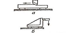
Cutting depth t when planing is equal to the thickness of the cut layer in one cut of the cutter (Fig. 1, a). When chiseling, the depth of cut is equal to the width of the cutter (Fig. 1, b). Planing feed s- the amount of movement of the part (on cross-planing and slotting steels) or the tool (on planing machines) in millimeters per cutter (table) stroke - mm / double stroke. Cutting speed V - average speed of the working stroke of the cutter (or part during longitudinal planing), m / min.
The woodworking power tool market also offers a variety of machine and grinding machines... Belt grinders are mainly used for rough grinding on flat surfaces... They are very widely used in finishing works to remove thick layers of material from large boards. Vibratory grinding machines, on the other hand, are used for more precise work when a small layer of material needs to be removed from a relatively small area and a smooth surface is achieved.
Delta lights are a variety of these machines. They are designed for hard-to-reach areas and small parts. Their main difference from classic vibratory grinders is the forward-moving working surface, which is triangular and has a smaller size.
Fig. 1: a - planing scheme, b - chiseling scheme
The depth of cut for roughing and semi-finishing planing is determined depending on the machining allowance. The maximum feed is selected according to technological requirements (depending on the requirements for the roughness of the machined surface, the strength of the tool holder, the strength of the machine mechanisms, etc.). The cutting speed is calculated using the semi-empirical formula
Another extremely useful tool for woodworking is a modern electric planer. In addition to their reliability and ergonomics, they are available with a wide range of different accessories that enable them to perform various tasks - smoothing surfaces, chamfering, grooving, precise sizing and much more.
The main working body of every electric planer is a rotating drum with fixed blades on it. Since wood is inherently heterogeneous in order to achieve the required smoothness on the surface, the electric motor, the rotating drum, must have sufficient power and a suitable rotation speed.
V = C v / (T m ∙ t x ∙ S y), m / min
where WITH v is a constant that takes into account the processing conditions (the use of coolant, the geometry of the cutter, etc.); T- period of tool life, min; t, x, y- exponents. The quantities WITH v , T, t, x, y - are taken from the reference literature.
A correction factor for the type of machine is introduced into this formula (for longitudinal planers - 1.0; for cross-planers - 0.8; for slotting-0.6). The found cutting speed determines the number of double strokes of the cutter (or table). According to the machine passport, the nearest lower value of double strokes per minute is taken and then the actual average cutting speed is determined. The selected mode is checked for power.
3. PLANERS
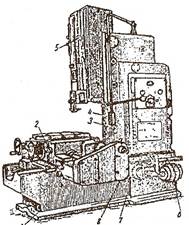
3.1. The device of the cross-planer model 7M36
The transverse planer with a hydraulic drive model 7M36 is universal and is designed for cutting flat and shaped surfaces with a cutter in individual and small-scale production.
The main units of the machine
This section is explored with the help of an apprenticeship wizard, who explains how the machine works and shows the main parts of it before the students start using the machine. The content of the section in the report on machine tool practice is not reflected by the student.
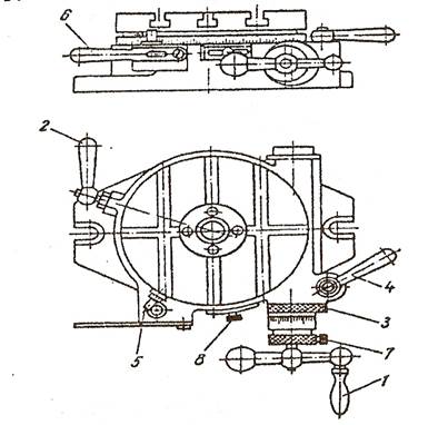
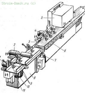
The machine consists of the following main units: bed 1, feed box 2, slide with cylinder 3, hydraulic drive 4, support 5, table 6, mechanical feed mechanism of support 7 and electrical equipment 8 (Fig. 2).
Rice. 2. Cross-planer with hydraulic drive model 7M36. Explanations in the text
Stanina The machine is a cast iron box-shaped body, reinforced with internal longitudinal and transverse stiffeners, mounted on a foundation slab. On the front wall of the bed there are guides for vertical movement of the table. On the top of the bed there are rectangular guides along which the slider moves. A hydraulic pump is attached to the rear wall of the frame, a plate with a hydraulic panel is attached to the right wall. On the left wall there is a window for mounting inside the hydraulic drive frame. The reservoir for the oil of the hydraulic system of the machine is interior bed.
Gearbox located with right side the crossbeams of the machine and is designed to carry out transverse and vertical table feeds for each double stroke of the slider, as well as to quickly move the table in horizontal and vertical directions. The accelerated movement of the table in these directions is carried out by a separate electric motor
Slider with cylinder is one of the main components of the machine. It is designed to transmit rectilinear reciprocating movements to the cutter slide and consists of a long cast iron hollow casting with rectangular guides and a hydraulic cylinder. The hydraulic cylinder is steel pipe with caps fixed at the ends. Inside the cylinder there is a piston with a rod, the end of which is connected to the slider.
Hydraulic drive intended for the implementation of the main movement - reciprocating movement of the slider, transverse and vertical feed of the table, starting and stopping the slider in any position. The hydraulic drive makes it possible to continuously change the speed of the main movement and the feed rate.
Support designed for fixing and feeding the cutting tool. The caliper can be moved manually and mechanically. Planing at an angle is carried out by rotating the support around the horizontal axis, the required position of which is fixed. The rotation angle is counted according to the scale marked on the turntable.
Knot "table" consists of a box-shaped table with T-shaped grooves for fastening workpieces and devices, a vertical plate having horizontal rectangular guides on one side for moving along the crossbar, and on the other - horizontal T-shaped grooves for fixing devices when the table is removed, and crossbars , which is a beam with horizontal and vertical rectangular guides. The vertical slab with the table attached to it moves along the horizontal guides, and the crossbar along the vertical guides. The horizontal movement of the table is carried out using a screw pair, the nut of which is attached to the vertical plate, and the screw is connected to the feed box. The vertical movement of the table is carried out using a worm gear. Both horizontally and vertically, the table can be moved both mechanically and manually.
Electrical equipment. The electrical equipment of the machine includes: the electric motor of the main drive, the electric motor of the drive of the accelerated movements of the table, the electromagnet for lifting the hinged board with a cutter during the idle run of the slide, the current collector and electrical equipment. Protection of electric motors and equipment from short-circuit current is carried out by fuses, and protection of the main electric motor from overloads - by a thermal relay. The switching on of the electrical equipment of the machine is carried out by a package switch located on the rear wall of the electrical cabinet. The electrical equipment mounted on the machine is made for a voltage of 380 V.
3.2. Planing machines
Planing machines are subdivided into single-column and two-column planers in pure planing (Fig. 3) and combined versions, edge planing, pit and portal planing. Single-column machines are designed for the processing of planes of large and heavy parts of large width and length.
The machine has two vertical and one lateral right calipers . The table is driven by a reversible DC motor through a two-speed gearbox and a worm and rack gear. The stepless and independent regulation of the speeds of the working and return strokes of the table is carried out by an electric drive according to the generator-engine system. The drive of the machine provides a smooth cut in the cutter and its slower exit from the workpiece. The machine is controlled from a control panel and a pendant push-button station.
Rice. 3. Double-column planing machine model 7231A
On single-column and double-column planers, medium-sized parts can also be processed, then they are installed in rows on the machine table in order to more fully and efficiently use the dimensions and travel of the table.
Combined planing machines are designed for planing and milling (models 7243F, 7288F), for planing, milling and grinding (model 7225) from one installation of large-sized products. Each such machine is equipped with three planing supports (two vertical on the crossbar and one horizontal lateral on the stand) and two milling carriages (one vertical on the crossbar and one horizontal on the stand). The 7225 is also equipped with a grinding head.
Edge planing machines are designed for planing sheet edges, as well as for chamfering at various angles. The processed sheet on such machines is pressed against a stationary table by a movable clamping device mounted on a carriage in the form of three spring-loaded rollers with an adjustable pressing force of the sheets. In addition, the sheet is additionally attached manually with clamps. Planing the edges of the sheets is done with two supports with a straight and. backward movement of the carriage. The electric drive of the carriage movement is made according to the generator-engine system and provides a stepless speed control of the carriage. The machine is controlled from the control panel on the carriage.
Pit longitudinal planers and gantry planers are designed for processing heavy parts of large dimensions (rolling mill beds, large engine frames, etc.). Unlike conventional planers in pit planing machines, the workpiece is installed on horizontal or vertical plates located in the pit, and a reciprocating movement is communicated to the portal of the machine, consisting of two racks and a cross member with vertical supports.
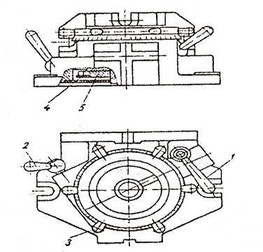
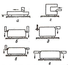
3.3. Slotting machines
Slotting machines are used for processing internal (keyways, grooves, polyhedral holes) and external flat and ruled surfaces.
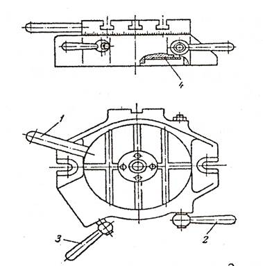
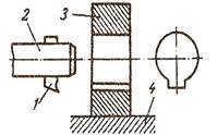
The principle of operation of slotting machines Let's take a look at the example of a slotting machine model 7430 (Fig. 4).
Machine characteristics. Chisel stroke range from 20 to 320 mm; diameter of the working surface of the table 500 mm; the limits of the number of double strokes of the chisel from 40 to 163 strokes / min; the power of the electric motor of the main movement is 3 kW.
![]()
Rice. 5. Schemes for the use of the main types of planing cutters: a - through passage for processing horizontal planes with a free cutter exit; b - checkpoint for processing horizontal planes, if the cutter does not have a free exit; in - undercut; d, e - combined for processing vertical and horizontal planes; e - scoring for processing vertical planes of large width with high feed; g, h - bent for processing angular planes; and, l - lateral for processing various grooves; k - slotted; m - shaped
4.2. Special cutting and auxiliary tools
Prefabricated planing cutters with mechanical fastening of cutting blades made of high-speed steel. In fig. 6 shows some types of prefabricated planing cutters with mechanical fastening of cutting blades made of high-speed steel, intended for thin planing of various surfaces of body parts: beds, carriages, stands, sleds, etc.
Planing cutters with tungsten carbide blades. Such cutters are designed for thin planing of body parts (Fig. 7).
Planing cutters with wedge-mounted cutting inserts. In fig. 8 shows a planing cutter with a wedge-mounted cutting insert, consisting of a holder and a cutting insert (Fig. 8, a), and in Fig. 8, b - a set of cutting inserts, from which you can quickly assemble the required type of planing cutter. The cutting insert is wedged in the holder by the cutting force and is held in the future in this position
Fig. 6. Planing finishing cutters with mechanical fastening of cutting plates made of high-speed steel: a, b - for processing planes; c - for trimming; d - for processing dovetail guides; d - undercut; e - for processing V-shaped guides; g- profile
Rice. 7. Planing cutters with brazed carbide plates: a - for trimming;
b - inclined scoring; в - one-sided for processing dovetail guides;
d - double-sided for processing dovetail guides;
d - for double-sided pruning.
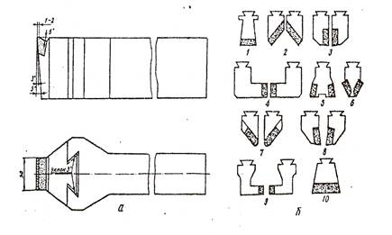
Rice. 8. Planing cutter with wedge fastening of replaceable cutting inserts with brazed carbide plates: 1 - slotted finishing; - checkpoint right and left; 3 - cut right and left; 5 - calibration; 6-chamfer; 7 - universal right and left; 8 - for processing dovetail guides right and left;
9 - for processing T-shaped grooves right and left; 10 - finishing wide
Multi-blade planer cutter with mechanical insert attachment. The advantage of such a cutter is that the required multi-edge insert can be inserted into the calibrated groove of the cutter holder. When blunt blades on one side, the plate is turned through an angle of 180 ° and is operated with the other blades.
An increase in labor productivity when working on planing machines largely depends on the design of auxiliary tools - tool holders, holders, etc. The use of universal tool holders allows processing parts at different angles. Some of them are equipped with flap bars designed to raise the cutter when the machine table retraces. The use of such an auxiliary tool reduces time, facilitates the work of machine operators, and increases productivity.
To reduce machine time when planing, one should strive to increase the depth of cut (at a given machining allowance), feed and cutting speed. For this purpose and for full use power of the machine, it is advisable to use multi-cutter planing with division of feed and removal allowance along the depth of cut between the cutters (Fig. 9).
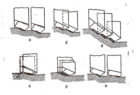
Rice. 9. Schemes of multi-cutter planing: a-planing with division of the cutting depth between two cutters in special multi-cutter heads; c - planing with the division of the cutting depth between three cutters; d, e - planing with feed division between two and three incisors; e - multi-cutter setting with a rough cutter
and a tool with a calibrating edge
5. DEVICES FOR INSTALLING AND FIXING THE WORKED PARTS
5.1. Devices for setting and fixing workpieces directly on the machine table
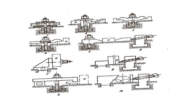
Installation and fastening of the processed parts, regardless of their dimensions, shape and type of processing, on the planer table are carried out using normalized parts, assemblies and fixtures. Normalized clamping parts include bolts, nuts, clamps, washers, clamping bars, universal supports, elbows, etc. (fig. 10). From various combinations of these parts, normalized clamping units are assembled (fig. 11).
Rice. 4. Slotting machine model 7430
The movements in the machine are carried out as follows. The workpiece can receive a longitudinal, transverse or circular feed. For this, on the main table of the machine 2, located on the horizontal guides of the bed, another rotating round table with a dividing mechanism is placed. The cutter is fixed on a slider 5 mounted on the vertical guides of the bed, and a reciprocating movement in the vertical direction is imparted to it. All the mechanisms of the machine are located on the base plate 1 in the machine bed 7. In the vertical guides located on the machine body 3, the slider 5 moves, making the working down and up the idle strokes.
A cutter is attached to the tool holder. The part is installed on the table 2, the machine has a feed box 8, a control panel 4 and an electric motor 6.
4. CUTTING AND AUXILIARY TOOL FOR
PLANING WORKS
4.1. Varieties of planing incisors and their use
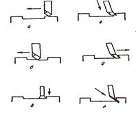
Cutters are the main cutting tool used on planers. Planing incisors are subdivided:
a) according to the location of the cutting edge - on the right and left;
b) according to the type of work performed - into checkpoints, undercutting, cutting, slotted, shaped, shaped;
c) by the nature of processing - for roughing and finishing;
d) according to the location of the head relative to the core of the cutter - into straight and bent;
e) according to the manufacturing method - into integral and composite.
At present, planing cutters are mainly made of composite, i.e. cutter heads (cutting part) are plates made of high speed steel or hard alloy, and the rods are made of high quality structural steel- steel 45,50,40X.
Schemes for the use of the main types of planing cutters are shown in Fig. 5.
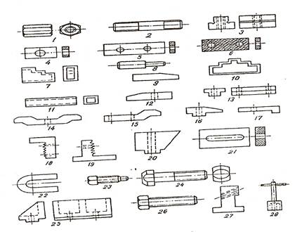
Fig 10. Standardized clamping parts: 1- nut; 2 - hairpin; 3 - biscuit; 4, W # - strips;
7.11 - linings; 8,16,20-stops; 9-wedge; 10-step support; 12,14,15,17 -picks;
13-block resistant; 8.19-composite universal supports; 23-set screw; 24-slot screw; 25-gon; 26-bolt; 27-clamping shoe;
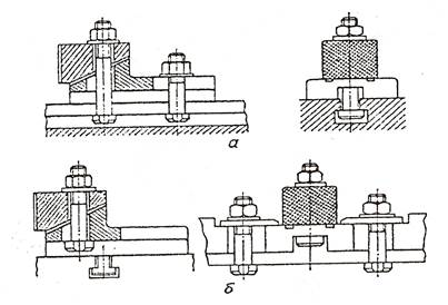
Rice. 11. Normalized clamping units assembled from normalized clamping parts: 1,2,3,4,9 - screw clamps; 5,6 - wedge clamp; 7 - fixing on a square; 8.10 - screw terminals; d - detail
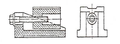
If the workpieces of complex shape and their fastening on the machine table are difficult, they are fixed on the setting squares (Fig. 12). For reliable fastening of parts with an uneven surface, clamps with a self-aligning ball bearing are used (Fig. 13).
Rice. 12. Setting squares for fixing the workpieces: a - normal;
b - rotary; в - universal
Rice. 13. Clamp with self-aligning ball joint
Figure 14 shows wedge clamps designed for transverse and longitudinal fastening of parts.
For installation on machine tables of body parts, adjustable supports are used - screw and wedge jacks, spacer screws, support split pads, as well as sets of measuring pads.
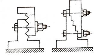
Screw jacks are usually used for mounting parts with rough mounting surfaces. They come in various designs, depending on the lifting capacity, the lifting height and the arrangement of the supporting parts (fig. 15).
Wedge jacks (fig. 16) are used for mounting parts during finishing. They allow vertical movement of the part to be installed with high accuracy (0.01-0.03 mm).
Rice. 14. Wedge clamps for fastening parts: a - transverse; b - longitudinal
Rice. 15. Screw jacks: a and b-simple; c and d - with spherical self-aligning washers
Rice. 16. Wedge jack
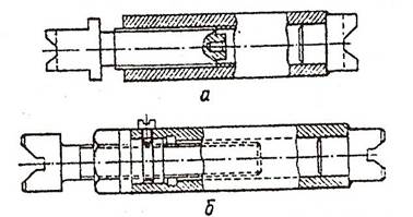
To install tall, unstable parts with hanging ends and create additional supports for them, spacer screws are used (Fig. 17).
Rice. 17. Spacer screws: a - made up to 400 mm long; b - made in length from
400 to 2 600 mm
The use of compound stands allows to reduce the time required for selection of supports of the required height (Fig. 18). Sets of measuring pads are used as stationary supports for the workpieces (Fig. 19). For a large longitudinal planer, for example, a set of eight spacers of various sizes is sufficient (tab. 1). From 1 - 3 shims of this set, supports of the required height can be assembled.
Rice. 18. Composite stands
Rice. 19. Measured pads
Table 1
A set of measuring shims for a large planer
5.2. Universal fixtures
The universal devices include: machine (machine) vices, rotary and indexing tables, dividing heads, etc. Machine vices are most widely used on planing machines.
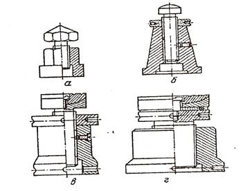
Machine vise used for fixing workpieces on cross-planing machines. They are divided into simple, rotary and universal (fig. 20).
Rice. 20. Machine vice, a - simple; b - rotary; в - universal
The machine vice is attached to the planer table with bolts, the heads of which are inserted into the T-slots of the table. Simple vices are the most rigid. The rotary vise is less rigid, but the workpiece can be rotated in the horizontal plane to the required angle, the value of which is measured along the dial.
Unlike swivel vices, the universal vice allows you to rotate the workpiece, both horizontally and vertically.
Machine vices are manufactured with manual, hydraulic and pneumatic drives. The use of a vise with a mechanized drive makes it possible to facilitate the work of the worker and reduce the time for fastening and unfastening the workpieces, and also ensures maximum processing accuracy.
Rotary tables(fig. 21) are used for setting and fixing the workpieces when planing straight sections at different angles to each other.
Rice. 21. Rotary table: 1 - handle for rotating the table; 2 - handle for locking the rotary part of the table; 3 - eccentric sleeve for disengaging and adjusting the gap of the worm pair; 4 - handle for locking the eccentric sleeve; 5 - movable table rotation limiter; 6-handle for releasing the table rotation limiter; 7 - screw for fixing the limb; 8 - screw for fixing the risk indicator
The workpieces to be machined can be clamped directly on the table, as well as using mounting and clamping devices. Rotary tables can also be used as indexing devices. The divisions are counted according to the table scale with the division value 1 and along the limb with a division value 2.
Dividing tables(rice. 22) are intended for installation and fastening of workpieces when machining dividing by
2, 3, 4, 6, 12 and 24 parts, on planers and other machines. Parts are fixed both directly on the table and with the help of mounting and clamping devices. Adjustment to the required division is performed by replacing the overlapping disc. The table is rotated manually.
Rice. 22. Indexing table: I - handle for rotating the table; 2 - handle for locking the rotary part of the table; 3 - latch handle; 4 - overlapping disc
Rice. 23. Dividing head: 1 - handle for removing the retainer; 2 - handle for securing the spindle; 3 - handle for turning the spindle; 4 - replaceable overlapping disc; 5 - replaceable dividing disc
Dividing heads(fig. 23) are intended for installation, fastening and turning of workpieces during machining on planers and other machines. The heads have a replaceable indexing disc with 24 cavities, which provide rotation of the spindle at angles that are multiples of 15. The spindle is rotated to other angles when replacing the main dividing disc with the corresponding location of the required number of cavities. The overlapping of the non-working cavities of the dividing disc is ensured by a special overlapping disc. The design of the dividing head also allows for graduation on a scale with a graduation value of 1, printed on the spindle flange. The dividing head spindle axis can be installed horizontally or vertically and equipped with a three-jaw chuck.
6. CONTROL AND MEASURING TOOL
6.1. General concept
Parts to be processed, processed and processed are subject to control (measurement), i.e. determine the degree of accuracy of their manufacture by comparing the dimensions obtained during measurement with the dimensions indicated in the drawing. The accuracy of measurements is influenced by the quality of the measuring tool itself, the ability to use the measuring tool, working conditions, the measurement method, etc. The contact method of measurement is the most widely used in factories. It is based on direct contact of the measuring tool with the workpiece being measured. Planers use the following standard measuring instruments - rulers, meters, vernier tools (calipers, depth gauges, calipers), gauges, templates, squares, protractors, indicators, straight rulers, etc.
6.2. Rulers, meters
Metal measuring rulers are manufactured with one or two scales with measuring ranges of 150, 300, 500 and 1000 mm. They are designed for external and internal measurements with an accuracy of 0.5 mm. The rulers have divisions (strokes) at a distance of 0.5 or 1 mm from each other. The ruler scale begins with the end face perpendicular to the longitudinal edge of the ruler. The end of the ruler is rounded and has a hanging hole. The rulers are made of heat-treated steel spring tape with a light polished surface.
Folding metal meters are designed for linear measurements with an accuracy of 0.5 mm by direct comparison of the measured dimensions with a scale of measures. Meters are made of ten steel elastic plate-links, hingedly connected to each other. When unfolded, such a meter is 1,000 mm long. Each plate has divisions (strokes) at a distance of 1 mm from each other. Link plates are made from cold rolled light polished steel strip. The beginning and end of the meter are end faces perpendicular to the longitudinal edges of the meter.
6.3. Vernier tools
Calipers they are produced in three types: with double-sided and one-sided arrangement of jaws (fig. 24).
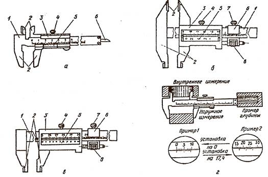
Fig. 24. Calipers: a-tipShTs-1 with double-sided t jaws; b-tipShTs-P with double-sided jaws; c - type ШЦ-111 with one-sided t jaws;
d - measurement examples
Calipers are designed for external and internal measurements, for measuring depths and heights with a measurement limit of 0, .. 125, 0 ... 200, 0 ... 320 and 0 ... 500 mm with a vernier reading of 0.95 and 0 , 1 mm. They consist of a bar 1 with divisions every 1 mm, a frame 3 with a vernier 5 having ten equal divisions at a length of 9 mm, i.e. each division of the vernier scale is less than the division of the bar scale by 0.1 mm, the depth gauge ruler 6 and screw 4. The bar and frame have two upper (for internal measurements) and two lower (for external measurements) jaws 2. Frame 3 moves along the bar during measurement and can be fixed in the desired position with a screw 4. Together with the frame, the depth gauge ruler b, which is designed to measure depths, moves along the groove of the rod. When measuring, an integer number of millimeters is first counted on a scale, and then tenths of a millimeter are determined using a vernier, which are then added to the whole number.
Gauge depth gauge(fig. 25) is intended for measuring the depth of grooves, openings, etc. Depth gauges are manufactured with a measurement range of 0 ... 200, 0 ... 320 mm with a vernier reading of 0.05 mm and with a measurement range of 0 ... 500 with a vernier reading of 0.1 mm.
It consists of a bar 1 with 1 mm divisions, a traverse 3 with a vernier 2, a micrometer feed device 4 with a nut 7 and clamping screws 5,6.
When measuring, the traverse with its base is placed on the edges of the grooves or openings, and the bar is lowered until the end of the bar touches the bottom of the measured depression.
Shtangenreismas designed for measuring heights from flat surfaces and for marking parts (fig. 26). Height gauges are manufactured with measurement ranges of 0 ... 250, 40 ... 400, 60 ... 630 mm with a vernier reading of 0.05 mm and 60 ... 630, 100 ... 1000, 600 ... 1600 , 1500 ... 2500 mm with a vernier reading of 0.1 mm. The height gauge consists of a rod 1 with divisions every 1 mm, rigidly fixed on the base 4, a movable frame 3 with a vernier 2, a micrometric feed device 7 with a nut 8, clamping screws 9, 10 and replaceable legs 5, 6, respectively, for measuring heights and for marking ...
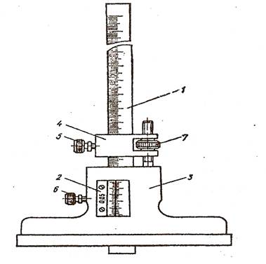
Fig. 25. Sliding depth gauge
Fig. 26. Shtangenreismas
6.4. Staples, templates, probes
To check the lengths, one-sided or double-sided sheet staples are used. In the measuring part, they have two sizes: one for the largest, through-flow (abbreviated PR), and the other for the smallest, non-through (abbreviated NOT) limit size of the part.
Templates used to check length, width, depth, radius, etc. Radius templates are standardized and are used to check the radii of convex and concave surfaces from 1 to 25 mm. They are produced in sets with nominal measuring radii: No. 1 from 1 to 6 mm, No. 2 from 8 to 25 mm, No. 3 from 7 to 25 mm. Verification is carried out by applying a template to the part and determining the deflection in the light.
Probes designed to check the dimensions of the gaps between surfaces. Manufactured in sets of 9 to 17 pieces with nominal thicknesses: No. 1 from 0.02 to 0.1 mm, No. 2 from 0.02 to 0.5 mm, No. 3 from 0.55 to 1 mm and No. 4 from 0.1 up to 1 mm.
6.5. Squares and protractors
Squares are designed to mark and control external and internal right angles, to control the mutually perpendicular arrangement of parts during the installation of equipment and to check the accuracy of the equipment.
For planing work, squares of the ULP, ULSh, UP, USh types of the 0.1 and the 2nd accuracy classes of the following dimensions are used: 60 x 40, 100 x 60, 160 x 100, 250 x 160, 400 x 250, 630 x 400 , 1,000 x 630 and 1,600 x 1,000 mm. In the specified sizes, the first number indicates the size of the long side, and the second - the short side. When controlling the outer corners of the parts, the square is applied to the plane of the corner to be checked inside, and when controlling the inner corners - with the outer side. Moreover, the square is applied by one side to the plane of the checked corner of the part, and the accuracy of the corner is determined on the second side of the square to the light.
Protractors with vernier are available in two types: UN - for measuring external and internal angles and UM - for measuring external angles (Fig. 27).
Rice. 27. Protractors with vernier: a - type UN; b - type of UM
Protractors of the UN type are produced with the measurement range of external angles from 0 to 180, internal angles - from 40 to 180 with a reading value according to the vernier 2 "and 5". They consist of base 1, vernier 2, micrometer feed screw 3, base ruler 4, stopper 5, sector 6, square 7, removable ruler 8 and holders 9.
Protractors of the UM type are produced with the measurement range of external angles from 0 to 180 with a reading value of 15 "vernier. 8 and square 9.
Angles are measured by various movements of the corresponding parts of the protractor. So, for example, when measuring angles from 0 to 90 with a goniometer of the UM type, an additional square 9 is put on the movable ruler 8, and when measuring angles greater than 90, the base ruler 1 and the movable ruler 8 are placed on the surfaces between which the angle is measured, and on the scale on the base 2 and Vernier 4 determine the value of the measured angle.
7. PROCESSING OF PARTS BY PLANING
7.1. Planing of parts on cross-planing and slotting
Planing horizontal planes. Before starting processing, it is necessary to check the fastening and correct position of the part in the vice or on the machine table. To create greater rigidity, the caliper is raised up so that the guide slides protrude from the bottom by no more than 5-10 mm, and the cutter is fixed in the caliper tool holder with the smallest overhang. Raise the machine table, bringing the workpiece closer to the cutter.
The cutter can be set to a given depth in different ways:
a) approximately, with a guaranteed undershoot of the cutter to a given depth (then the required cutting depth is achieved by trial passes of the cutter and a scale ruler);
b) by means of divisions on the caliper screw dial;
c) using a height gauge;
d) using a mounting block (Fig. 28, a);
e) using measuring plates (Fig. 28, b);
f) using special devices.
Then the stroke length is set and adjusted, the position of the slider relative to the workpiece is fixed and the support is fixed with a side stopper. The required cutting modes (depth, feed and speed) are selected and installed on the machine and planing is started.
Depending on the technical requirements distinguish between rough and final planing. Rough planing works with the greatest depth and feed. The plane to be machined is planed, depending on the allowance, in one or more passes. After processing, check the compliance of the obtained dimensions with the dimensions specified by the drawing.
In finishing planing, the accuracy and cleanliness of the machined surfaces depend on the selected cutting conditions, the geometry of the cutting edge of the cutters, and the accuracy and rigidity of the technological system. For finishing planing, depending on the dimensions of the planes to be machined and technical requirements, a machining allowance of 0.5 ... 1.5 mm is left.
Rice. 28. Setting the cutter to a given cutting depth: a - using an adjusting block; b - using measuring tiles
Planing vertical and horizontal planes. On cross-planers, vertical planes are usually planed in a horizontal position, because the planing height in the vertical plane is limited. Planing of vertical and horizontal planes is carried out mainly when it is necessary to process vertical and horizontal planes from one installation.
Planing of inclined planes. Inclined planes, like vertical ones, should be treated as horizontal if possible. For planing inclined surfaces, the support and the turntable are turned at the appropriate angle.
Planing grooves and grooves. For planing grooves and grooves, slotted cutters are used. Vertical feeding is carried out by a slide. When planing blind grooves for the entry and exit of the cutter, blind holes with a diameter and depth of slightly larger groove dimensions are drilled at the ends of the intended groove.
The most common schemes for processing parts on cross-planing machines are shown in Table 2.
table 2
Schemes for processing parts on cross-planing machines
| Processing scheme | |
 | Planing horizontal planes The swivel part of the support is set to zero degrees, and the folding board is set to the middle position. |
 | Planing of vertical planes Planing is carried out according to the scheme (a) when using scoring cutters or according to schemes (b) when using through cutters. Scoring cutters are used in cases where there is a danger of jamming the machine table. It is necessary to install the parts on the machine table so that the machined surface is above the table groove to allow the cutter to exit. |
 | Planing dovetail grooves Planing the upper horizontal planes (a). Planing of the lower horizontal plane (b). Planing vertical planes (c). Planing an inclined plane (d). Planing the lower horizontal plane (e). Cutting the groove (e). |
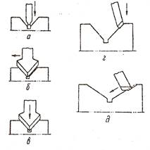 | Machining prisms When machining, the groove (a) is cut first. If the inclined plane has a significant width, then the processing is performed with a shaped cutter with a horizontal feed (b). When the width of the inclined plane is small; processing the entire profile at once with a shaped cutter using a vertical feed (c). Planing of inclined planes is also carried out by means of passage, cutters with vertical (d) or inclined (d) feed. More productive; is machining with vertical feed, since with this method it is possible to work with a smaller overhang of the cutter. |
 | Planing a groove in a hole 1 - cutter; 2 - mandrel; 3 - work piece; 4- machine table |
7.2. Planing of parts on planing machines
After installing, fastening and checking the correct position of the workpiece on the machine table, they begin to set it up. The calipers are set in zero position and pulled up. The cross member with calipers is lowered as close to the workpiece as possible. The cutters are set with the smallest overhang, and the length of the table stroke - taking into account the length of the workpiece. The cutters are set with the smallest overhang, and the length of the table stroke - taking into account the length of the surface to be processed and the overrun of the table at the beginning and at the end of the working stroke. Then, depending on the need, a rough or final planing of the treated surface is carried out.
It should be noted that for finishing planing, it is necessary to select the most accurate and rigid machines on which rough planing cannot be performed. Such machines must be isolated from other working machines and devices, they must be subject to periodic checks for compliance with accuracy standards.
Rough planing. The allowance for rough planing is usually removed in one pass at the greatest depth of cut and feed allowed by the rigidity of the part, the reliability of the fastening and the power of the machine. If the allowance is large and it is impossible to remove it with one cutter in one pass, then they are removed in two passes or two cutters are installed in the tool holder. For roughing cut depths see
Table 3.
Table 3
Maximum depth of cut for roughing cuts
It is known that in large castings and forgings during their manufacture, significant internal stresses arise, which must be removed before roughing or semi-finishing operations. To remove them, the parts are subjected to artificial or natural aging. Usually, after removing the upper layer from the surface of the part, the internal stresses are redistributed and the part is deformed, therefore, after the rough cut, the part must be released from the fastening and re-fastened before finishing.
Fine planing. After rough processing, the parts are subjected to semi-finishing, fine and fine planing. With increased requirements for the accuracy and cleanliness of the processed surface, after roughing, semi-finishing planing is performed with passing cutters.
For finishing planing, use finishing cutters with a feed of 1.5 - 4.0 mm / double stroke or wide cutters with a feed of 10-20 mm / double stroke. With fine planing, surfaces of 4-6 cleanliness classes are obtained.
Fine planing is carried out with fine wide cutters with feed rates for preliminary passes 10-20 mm / double stroke and for final passes 12-16 mm / double stroke. With fine planing, surfaces of 7-8 cleanliness classes are obtained.
To obtain a high cleanliness of the processed surface during final planing, cutting lubricants (cutting fluid) are used. The depth of cut during finishing is set using measuring plates, an adjusting block, a height gauge or special devices. The cutting edge of cutters intended for fine planing is carefully refined. Cutters equipped with carbide plates with a bent shaft have found the greatest application in finishing planing, since they are more resistant to vibration.
After the end of planing, the processed parts are subjected to control in accordance with a given drawing and technical conditions... For control, a universal and special measuring instrument is used. The most used schemes for processing parts on planing machines are shown in Table 4.
Table 4
Schemes for processing parts on planing machines
| Processing scheme | Type and sequence of processing |
 | Planing with two slides on a solid horizontal plane. Rough planing of a solid horizontal plane equal to the width of the table is carried out in the following sequence. With the cutter 1 (a), they start from one edge of the part, and with the cutter 2 they cut in on the other side using the opposite feed in the area located at a distance of a quarter of the width from the second edge of the part. Having processed half of the surface with a cutter 2, move it and cut from the edge of the part (b). This technique makes it possible to process the plane simultaneously with two calipers with opposite feeds. |
 | Planing of one plane: vertical slide (a); side support (b) |
 | Planing parallel planes: with a vertical support of one plane, based on a previously processed plane (a); vertical and lateral calipers of two planes at the same time (c); lateral support of the inner surfaces (g); lateral support of one plane with alignment along the previously processed parallel plane (e); side calipers simultaneously of two planes with a small overhang of the calipers (e) |
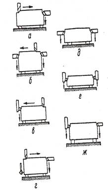
| Planing perpendicular planes: side and vertical supports simultaneously (a); vertical and side calipers with a small overhang. With a large plane width, two vertical supports are used; the finishing pass is performed with one slide (b); vertical supports of the horizontal and lateral plane (c); vertical and lateral calipers with installation and alignment along two perpendicular previously processed planes (g); with the installation of one processed plane: lateral calipers of one plane or simultaneously two lateral planes (with a small overhang) (e); vertical calipers of one or simultaneously two lateral planes (e); lateral and vertical calipers of two planes simultaneously or sequentially (g) |
| Planing horizontal and vertical planes: plane 1 (a); with a scoring cutter in two passes, plane 2 (b) is processed |
 | The sequence of planing T-shaped grooves: planing a vertical groove (a), cutting a right groove (b), cutting a left groove (c), chamfering (d), calibrating a vertical groove with a round cutter (e) |
 | Planing a blind groove: with free cutter entry (a); without free entry and exit, cutting (b). |
8. ORGANIZATION OF THE PLANER'S WORKPLACE
The workplace is the smallest section of the production area of the workshop, where the equipment, tools, devices, accessories, blanks and finished products necessary for work are most rationally located.
Unsatisfactory organization and maintenance of workplaces lead to losses of working time. Moreover, a significant amount of time is spent by the main workers on the performance of various auxiliary work (carrying out workpieces, sharpening tools, obtaining technical documentation, etc.). To eliminate these unproductive losses of working time, when organizing a planer workplace, issues of external and internal planning are resolved.
The external layout of the workplace includes: placement of the main equipment, organizational equipment, lifting and transport vehicles, auxiliary devices and devices, blanks and finished parts.
Internal layout the workplace includes: the location in the tool cabinets of the cutting, measuring and auxiliary tools and equipment, as well as tools for the care of equipment and maintaining cleanliness in the workplace.
Basic requirements for the organization and maintenance of the planer workplace:
1. Standards for distances between machines and from machine tools to walls and columns of buildings, funds for the operating time of equipment and workers, sanitary and hygienic conditions air environment and lighting in working area production facilities must comply with the standards technological design machine-building plants and sanitary standards design of industrial enterprises.
2. When planning a workplace, it is necessary:
a) choose optimal sizes production areas for the placement of equipment and tooling to produce, taking into account the sequence technological process and creating convenience for the worker to apply advanced techniques and methods of work;
b) provide for the economy of movements and forces of the worker due to the rational arrangement of receiving tables for parts, tool cabinets, racks, tool pads, technical documentation and organizational equipment.
3. The workplace should be equipped with basic equipment, technological equipment, organizational and technical equipment, technical and organizational documentation, lifting vehicles and auxiliary devices, communication equipment, lighting devices, protective devices and individual protective equipment safety seat for short-term rest during breaks or to monitor equipment.
4. The number of cutting, measuring and auxiliary tools and devices should be the minimum necessary and arranged in a certain order, and the most frequently used tools should be within the optimal reach of the planer.
5. All processed and processed parts should be stored in containers, on stands or tables.
6. To collect and remove chips from the workplace, special devices should be provided.
7. The sanitary and hygienic conditions of the workplace must comply with the current sanitary standards.
8. The color finish (painting) of the production area, equipment and accessories must meet the requirements of technical aesthetics.
9. The workplace must be provided with the necessary maintenance.
10. When organizing a workplace, it is also necessary to provide for the effective use of equipment, tools, devices, accessories and workpieces.
The planning, equipment and maintenance of the planer workplace, even for one type of machine, can be different and depend in each case on the nature and conditions of the work performed, and are also made taking into account the equipment used and the dimensions of the workpieces (Fig. 29).
Rice. 29. An example of the layout of the workplace
9. SAFETY WHEN WORKING ON PLANERS
Compliance with safety regulations is a prerequisite for preventing occupational injuries and increasing labor productivity.
When working on planing machines, moving parts that move back and forth are especially dangerous. On a cross-planer, this is a slider, and on a planer, a table and devices installed on it with the processed parts. Therefore, these units of planing machines are subject to increased requirements in terms of fixing fixtures and workpieces on the table, cutting tools, as well as fencing the cutting zone and moving parts of the machine.
It is necessary that sufficient passages remain in the area of movement of the slide or table and there are no foreign objects.
When processing parts on planing machines, injury from flying off metal shavings is possible. To prevent this, safety devices - protective screens and shields should be installed on machines in dangerous places, and the planer should use safety goggles. To remove shavings from planing machines, you must use brushes and special hooks.
When working on planing machines, special attention should be paid to electrical safety.
The safety of work on the planer also depends on the correct and rational organization of the planer workplace.
Before starting work, the planer is obliged.
1. Tidy up work clothes and workplace.
2. Take the machine clean from chips and dirt from the changer, check it technical condition, serviceability of lifting devices, fastening devices, cutting and auxiliary tools and workpiece.
3. Check the serviceability of the guards and protective devices.
4. Check the electrical grounding of the machine.
5. Adjust local lighting, wipe fittings and light bulbs.
6. Check at idle speed of the machine: the action of starting, stopping, reversing and braking devices, fixation of the engaging and switching handles; lubrication system; movement of machine units.
7. If you find faults or malfunctions in the machine, inform the foreman and do not start work until they are eliminated.
8. If the machine does not have special safety devices for flying chips, wear safety glasses or a shield.
During work.
1. Install and remove heavy parts and devices only with lifting devices. Do not exceed the specified lifting capacity for mechanisms and parts of single-gripping devices.
2. When working on heavy planers, if it is impossible to maintain the machine and observe the processing of the part from the floor, you must use strong and stable stands or ladders.
3. Stop the machine and turn off the electric motor in case of temporary interruption of work, power outage, installation and removal of parts, cleaning, lubrication, etc.
4. If voltage appears on the metal parts of the machine (feeling of electric current) or the ground wire is cut off, stop working and inform the foreman immediately.
5. During machine operation, do not tighten fasteners, do not hold parts and tools on the machine, do not stand on a moving table.
6. Do not allow persons who are not related to the work performed to enter their workplace.
7. When sharpening a cutting tool on sharpening machines(in the absence of the center
Lumber, or blanks that enter after cutting for further processing, as a rule, have risks, roughness, warping and other defects that are easily eliminated during planing.
When planing (along with the elimination of these defects), it is necessary to obtain an accurately calibrated (base) surface so that, focusing on it, it is possible to align the rest of the surfaces and have parts of the correct shape.
A part of the correct shape is obtained if, during processing on a planer, it occupies a certain position in relation to the cutting tool and guides (table, ruler), while the accuracy of the part depends on how well the face and edge adjacent to the setting devices are verified (ruler). Planing usually results in smooth and profiled surfaces.
For planing, planing, thicknessing and four-sided planing machines are used.
The purpose of the planing machines is to align the surface of the part along the plane and into the corner. When planing on a planing machine, a base surface is created on the parts, which is necessary for their further processing on machines. Our industry produces planing machines with manual and power feed.
The machines with manual feed include jointing machines SF4-4 and SF-6; for machines with mechanical feed - double-sided planer S2F-4 with automatic feed.
Joiners with manual feed are widespread in the production of joinery and can be recommended for enterprises with a small production volume - up to 100-150 thousand m2 of joinery products per year. At large volume production should use planing machines with a mechanical feed, as the most productive and safe in operation.
A planing machine with automatic feed (Fig. 127), used for simultaneous planing of the face and edges of the workpieces, is a cast iron bed on which, on eccentric supports, the front and rear plates of the working table are located. Between the plates there is a horizontal knife shaft with a diameter of 125 mm, a length of 410 mm, rotating in ball bearings. The knife shaft is driven by an electric motor with a power of 2.8 kW through a V-belt transmission. On the plates there is a guide fence 1, 11.
Rice. 127. Diagram of a double-sided planer machine:
1 - fixed part of the ruler. 2 - fixing screw, 8 - background-matte, 4 - stands, 5 - V-belt transmission, 6 - electric motor, 7 - screw adjusting the belt tension, 8 - plate for installing the electric motor, 9 - handle for installing the bracket, 10 - eccentric for adjusting the installation of the movable part of the ruler, 11 - the movable part of the ruler, 12 - knife head, 13 - spindle
The amount of the removed layer of wood is regulated by raising or lowering the front table with a handle with a height indicator. The position of the back plate is adjusted with a screw and nut. In addition to the horizontal knife shaft, a vertical knife head 12 is mounted on the machine, with which the edge of the workpiece is planed. The vertical knife head is mounted on a spindle 13 mounted on a special support. The spindle of the vertical knife head is driven by an electric motor 6 with a power of 1.7 kW through a V-belt transmission 5.
The supply of workpieces and lumber to the horizontal knife shaft and vertical head is carried out by an automatic feeder driven by an electric motor through a gearbox. The ADF can be moved both vertically and laterally. The machine of this design can be integrated into a semi-automatic line for the processing of block parts.

Rice. 128. Scheme of the planer machine

Rice. 129. Devices for safe work on the planing machines:
a - fan-type fencing, b - pressure block; 1 - block, 2 - handle, 3 - blank
Work on jointing machines. The main task of processing on a planer machine is to obtain a completely flat and straight face and one side edge in such a way that they are at right angles to each other. During further processing on thicknessing, planing and molding, tenoning and other machines, these surfaces are basic - from their correctness and accuracy; the quality of the parts depends. It should be noted; that if the workpiece has a curvature of the face and edges, then after processing on thicknessing and planing and molding machines, these defects remain in the finished part, and on tenoning, drilling and grooving and other machines, this leads to distortions of the spikes, holes and sockets, which results in low quality products.
The scheme of the jointing machine is shown in Fig. 128. Before working on the jointing machine, it is necessary to inspect the workpiece 8, and the processing should be carried out from the concave side, directing it to the knife shaft 1 in such a way that no scuffing of the fibers from the counter stratum is obtained. It is necessary to feed the workpieces onto the cutter shaft evenly, without jolts.
Curved workpieces should not be processed, since you still will not get a high-quality part. The workpiece must be planed until a clean surface is formed without roughing. The quality of gouging on a planing machine is checked as follows: the planed workpieces are folded with machined edges or layers, if there are no gaps between them, then the processing is considered sufficient
When working on the machine, it is necessary to follow safety rules, since an open rotating shaft is very dangerous; the knife shaft must be equipped with a fan-shaped guard (fig. 129, a), opening only during the passage of the workpiece and automatically closing after processing the workpiece. Short workpieces must be processed using a clamping block (fig. 129, b). The machine should be adjusted in such a way that the gaps between the knife blades and the plates are minimal; in addition, the surface of the slabs must be horizontal.
Thicknesser machines are designed for planing parts to a given size in thickness and creating strictly parallel planes. Distinguish between single-sided thicknessing machines (СР6-6 and СР-12-1) for planing one plane and double-sided (С2Р8-2 and С2Р12-1) for simultaneous planing of two parallel planes.
Technical characteristics of thicknessing machines are given in table. thirteen.
|
Indicators |
Bilateral |
Unilateral |
|
|
Maximum planing width |
|||
|
Product thickness in mm |
|||
|
The smallest length of the processed material in mm. |
|||
|
Knife shaft diameter in mm |
|||
|
Cutter shaft speed |
|||
|
Feed rate in m / min |
Stepless 4,2-25 |
||
|
Number of knives |
|||
|
The total power of electric motors in ket. |
|||
|
Machine dimensions (length X width X height) in mm.... |
2025X2900 X X1800 |
1615х1585х Х1550 |
1100Х1380ХХ1560 |
|
Weight in kg.......... |
|||
The thicknessing planer СР6-6 is used for one-sided planing of boards, bars and boards up to 630 mm wide and from 5 to 200 mm thick.
The machine is a cast iron bed, on which a table, a knife shaft, a feed mechanism and drive mechanisms are located. The machine table can be moved up and down using a lifting mechanism driven by an electric motor. The height of the table is set depending on the thickness of the workpieces being processed.
The knife shaft, rotating in bearings, is driven through a V-belt transmission from an electric motor. The material feeding mechanism is set in motion from the cutter shaft through a V-belt transmission and a four-speed feed box.
The material is fed by two upper and lower rollers, of which the upper, front, has a sectional design (Fig. 130). On the sectional shaft 5, rings with a corrugated surface 3 with rubber fingers 4 are put on. The presence of rings and rubber fingers allows the machine to simultaneously process workpieces with uneven thickness within 4 mm.

Rice. 130. Diagram of the sectional grooved roller of the thicknessing machine:
a - workpiece feeding scheme, b - corrugated roller design; 1 - bearing, 2 - stand for fixing the pressure device, 3 - ring, 4 - rubber fingers, 5 - shaft for installing rings
The lower smooth feed rollers, on which the processed block rests, protrude from the plate to an insignificant height (2 mm), and this amount of protrusion can be adjusted by screws located at their ends. For efficient machine operation, the rollers must protrude to the desired height and equally at both ends.
Above the knife shaft, there is a pivotally rising massive metal cap, the front sharp edge of which rests on the planed material in front of the knives of the rotating knife shaft. By pressing the sticks against the table to reduce vibration, the sharp edge of the hood acts as an additional chip breaker for quality gouging. The height of the position of the clamping cap is adjusted by the support adjusting bolts.
Anti-blowout "claws" are installed in front of the feed rollers to prevent the possible throwing of thinner blocks back by the knives. The machine is equipped with a device for point and jointing of knives directly on the machine.
Thicknessing machine SR-12-1 is designed for planing from one side of wooden panels, parts of windows and doors up to 1200 mm wide, as well as for cleaning the surface of assembled window sashes and door leaves. In one pass on the machine a layer of wood up to 2 mm thick. The design of the machine allows you to simultaneously plan several workpieces with uneven thickness up to 4 mm.
Rice. 131. Diagram of the device of a double-sided thicknessing machine C2P8-2:
1 - movable table located after the lower shaft, 2, 3, c, 9, 10 - feed rollers, 4 - clamp, 5 - lower knife shaft, 7 - sharpening device, 8 - upper knife shaft, 11 - handwheel of the lifting mechanism and lowering the table, 12 - table, 13 - chain, 14 - handle, 15 - handwheel of the mechanism for moving the rear table in height
Thicknesser double-sided machines are designed for simultaneous planing of joinery parts to a given size in thickness. The machines can simultaneously plan several parts with a thickness difference of up to 4 mm. A diagram of a double-sided raismus machine C2P8 = 2 is shown in Fig. 131.
The thicknessing machine C2P8-2 is intended for double-sided planing of products or boards up to 800 mm wide. On the machine bed there is an upper block with upper feed rollers 3, 6, 9 and an upper cutter shaft 8. There is also a table on the bed, on which the lower cutter shaft 5 is installed, which is located behind the upper cutter shaft in the course of processing parts. Table 1 can be raised or lowered through a mechanism driven by a 1 kW electric motor, or manually. The material for processing is fed by feed rollers through a gearbox of a four-speed electric motor. For a quick stop knife shafts the machine is equipped with electromagnetic brakes.
The thicknessing machine С2Р12-1 is approximately similar to the machine type С2Р8-2, but has a planing width of 1250 mm. Both machines are equipped with knives point and planer.
Work on thicknessing machines. To obtain parallelism of opposite seams or edges, the workpieces are planed from one and both sides on thicknessing machines. The processed bars (workpieces) are placed on a horizontal table and directed by the feeder (rollers) to the rotating shaft on which the knives are located. In single-sided thicknessing machines, the knife shaft is located at the top, and in double-sided thicknessing machines - at the top and bottom of the workpiece being processed. To improve the cleanliness of planing, the machine is equipped with clamping blocks, which, by pressing on the workpiece, protect it from vibration.
Workpieces processed on planing machines are fed into the thicknessing machine. When processing blanks without preliminary planing, that is, warped, substandard parts are obtained. This is due to the fact that, under the pressure of the feed rollers, the workpiece is first leveled, and when it leaves the machine, it again takes on its original warped shape.
When working on a thicknessing machine, it is necessary to ensure that the working width of the machine table is used as fully as possible - for this, simultaneously lay the maximum number of bars - the workpieces to be processed. The workpieces are fed into the machine end-to-end, that is, end-to-end. Bars with pronounced defects should not be fed into the machine, since after planing the bars will be rejected.
Sliced bars should not have any pinholes, tears, hairiness, or notches (convex). The presence of hairiness and scratches indicates that the workpieces were planed with blunt knives. The waviness on the surface of the planed blocks is a consequence of the clogging of the chips between the knife and the chipbreaker. Kicks or tears on the bars are caused by the pressure block being poorly adjusted (pressed down).
Before working on the machine, you should check how correctly installed and well sharpened the knives. The planes of the knife shaft, on which the knives are applied, must be clean, without dents and dents. The edge of the chipbreaker must be straight and free from gouges. It is also necessary that the machine table has a clean, horizontal surface without potholes. The feed mechanism (grooved or sectional and smooth) must not be skewed or bent.
To prevent beating of the shaft, balanced knives of the same weight, thickness, width and length are installed on the neg.
When working, you must strictly follow the safety rules. The length of the planed parts should be 50 mm longer than the distance between the axes of the feed (front and rear) rollers. In order to avoid the back throwing of the bars, the machine is equipped with sectors (retaining claws); the feeder and rotating parts of the machine (shaft, drive, etc.) must be necessarily fenced; it is forbidden to clean, set up and repair the machine on the go
Four-sided planers C10-2, C16-4 and C26-2 are designed for planing joinery parts from four sides with the creation of a profile. Machines with 4-5 working spindles are produced; They have lower and upper horizontal knife shafts, with which the faces of parts are planed, as well as vertical (right and left) knife shafts, which serve for smooth and profile planing of edges.
Rice. 132. Four-side planer С10-2:
1 - support for the fifth lower molding spindle, 2 - support for the upper horizontal spindle, 3 - right vertical spindle, 4 - support for the lower horizontal spindle, S - support for the feed mechanism, 6 - horizontal clamping device, 7 - support for the left vertical spindle, 8 - bed, 9 - guide rulers, 10 - base plates, 11 - clamp
On four-sided planing machines (after the vertical knife shafts) there is a fifth additional knife shaft, designed for profile planing of the face or for sawing the planed parts into several parts. If there is a fifth knife shaft on the machine, you can simultaneously plan two or more parts from one workpiece, cutting them immediately after gouging. At many enterprises, using such a machine, they plan simultaneously two bars of window sashes, etc.
On planers, the work spindles are positioned in such a way that it is more convenient to install the tool. The supports, in which the spindles are mounted, can be moved both vertically and horizontally. The supply of materials for planing is carried out by a feed mechanism, and on machines operating at a feed rate of more than 25 m / min, there is a special feeding table that ensures the continuity of material supply to the machine. The diagram of the four-sided planer C10-2 and its individual units are shown in Fig. 132.
The four-sided planer C10-2, designed for planing from four sides with the creation of a profile, is a cast-iron assembly bed on which the roller-track feed mechanism, guide rails, clamping mechanisms and knife shafts are located. The presence of the 5th shaft on the machine allows, along with planing, to cut the planed parts along. On the machine, mainly parts are processed - window sash bars, glass layouts, cover strips, ebbs, covers for panel doors, etc.
The four-sided planer С16-4 hardly differs from the С10-2 machine, except that on this machine you can plan parts up to 160 mm wide (instead of 100 mm on the С10-2 machine) and 10 to 80 mm thick (instead of 6- 50 mm). Designed for planing from four sides with the creation of a profile of the following joinery parts: cabinet box bars, layouts, covers, cover strips, window sashes, baseboards, fillets, platbands, etc.
The four-sided planer C26-2, designed for planing from four sides with the creation of a profile, is a more powerful machine - it can handle parts of larger sections.
The machine is a cast-iron prefabricated bed with a roller-caterpillar feed mechanism and base plates, slides with cutting heads, clamping mechanisms and guide rails located on it. The machine has five knife heads, arranged in the following order: lower horizontal, right and left vertical, upper horizontal and lower molding. Instead of the molding head, a support with a vertical spindle can be installed.
On the C26-2 machine, mainly the bars of window and door frames, bindings, boards of a clean floor, etc. In addition, on this machine, along with planing, you can longitudinally saw processed parts.
Planing cutting tool. For planing, a cutting tool is used in the form of knives and cutters, which are attached to the shafts. Knife shafts are round (for attaching thin knives) and square (for attaching thick knives). Square shafts are used only in thicknessing and four-sided planing machines; Do not use them on hand-fed planers as this could result in injury.
Depending on the design, knife shafts can be mounted from 2 to 32 knives. Thin knives are attached to the knife shaft with pads pressed against the shaft by bolts or wedge-shaped inserts. The last method of fastening is the most durable and widely used.
When planing, use flat knives (GOST 6567-61) with a straight cutting edge (Fig. 133); for profile planing - shaped knives; for smooth and profile planing - cutters (cutters).
Shaped knives for profile planing have recently been replaced by milling cutters.

Rice. 133. Flat knives with a straight cutting edge for wood milling:
a - without slots (thin knives), 1 - rear edge, 2 - outer edge, 3 - front edge, 4 - longitudinal edge, B - cutting edge, 6 - end edge; b - with slots (thick knives): L-length B - width
Flat knives with a straight cutting edge are used for planing on planing, thicknessing and four-sided planing machines. Knife thickness 3 and 10 mm. Knives with a thickness of 3 mm are used for planing and four-sided planers with a knife shaft for four or more knives; knives with a thickness of 10 mm - mainly for square shafts of thicknesser and four-sided planers. In the plane of such knives, slots are made for fastening bolts.
Thick knives (10 mm) - two-layer, the main part of the knife is made of mild steel, the welded (cutting) part is made of quality steel thickness 2.5-3.5 mm. The length of the thick knives is from 40 to 310 mm, the width is from 100 to 125 mm.
Thin knives (3 mm) - single-layer, without slots, made of high quality steel. The length of thin knives is from 30 to 1610 mm, the width is 25-45 mm.
Before installing the knives on the machine, they must be well sharpened and balanced so that they have the same length, width, thickness and weight. The knives are balanced using a special device or balancing scales; the difference in weight of paired knives is allowed no more than 0.5%. In addition, the knife shaft to which the knives are attached and the fasteners must also be balanced.
When installing the knives on the shaft, make sure that they fit snugly against the supporting surfaces, paying particular attention to the tightness of the front edge of the knife to the edge of the chipbreaker. The knives must be installed in such a way that their cutting edge protrudes no more than 1 mm beyond the edge of the chipbreaker. Attach (tighten) the knives with bolts alternately, starting from the middle of the shaft to the edges.
Milling cutters are tools that are widely used in the manufacture of joinery. The cutter has 4-6 cutters, its installation is very simple, working with it is safer than with knives. The quality of planing when working with milling cutters is much better than when working with knives. In the production of joinery and construction products, mainly end and shell cutters are used: end - when working on milling and tenoning machines; mounted - on planers and milling machines... Distinguish between solid (profile) and compound shell cutters. Solid cutters are used little, since after each sharpening they have a broken tooth profile; composite - are widely used for precise processing of profile parts.
Compound cutters are a set of cutters held together by pins; as a result of adjusting one cutter relative to the other, the angular parameters are preserved, therefore, after sharpening, the profile of the part remains unchanged. The cutters are produced according to the normals. The diameter of the cutters is from 80 to 180 mm, the number of teeth is from 4 to 8.
Angular parameters: -35 ° -20 ° - rake angle; p = 60 ° -45 ° - angle of sharpening; a = 10 ° -15 ° - back angle.
For the processing of the right porch of window sashes, a one-piece cutter (Fig. 134) with a diameter of 160 mm with four teeth is used.
The compound cutter for processing the groove of the door leaf, lined with solid fiberboard (Fig. 135), consists of three cutters connected by pins. The knives are fixed to the cutter body with screws 1 and a wedge 3. The cutter has a durability 15-20 times higher than that of conventional cutters. The cutter body and knives are made of 45 grade steel, the plates are made of VK-15 alloy.
Work on four-sided planing machines. A four-sided planer usually has two or three horizontal working shafts and two vertical ones.

Rice. 134. Milling cutter for processing the right porch of window sashes
Knives installed on one working tool must have the same weight, length,

Rice. 135. Composite milling cutter for processing the groove of a door leaf, lined with solid wood fiber board: 1 - screw, 2 - knife, 3 - wedge, 4 - hard alloy plate, 5 -
Cutters mounted on vertical shafts must be well balanced and sharpened. When installing knives and cutters, it is necessary to strive to ensure that the loads on the knife shafts arising during planing do not exceed the permissible ones, that is, so that the removal of chips is as minimal as possible.
In four-sided planers, all cutting heads and feed are shielded. The cutter shafts and heads must be round, except for those cutter shafts that are covered with blind covers. The fastening of the knives in the heads and shafts must be reliable and predominantly wedge-shaped. The machine feed mechanism is blocked with the cutting heads in such a way that the feed cannot work before starting them.
The clamping mechanisms (roller, block) are installed in such a way that the processed block can freely pass into the machine and not vibrate at the same time. The feeding mechanism (upper feeding rollers) is adjusted so that in the lowered state their height corresponds to the thickness of the bars after planing; the bottom feed rollers usually protrude no more than 1.5-2 mm above the tables.
Before work, the fastening of knives and cutters is carefully checked, after which horizontal and vertical shafts are alternately launched, then control bars, and only after inspection and measurement (if the machine is set up correctly) they start work.
The material (bars, boards) into the four-sided planer must be supplied continuously, without breaks, that is, end-to-end. You cannot serve bars with rot and other defects, as well as with metal inclusions (nails, etc.). It is strictly forbidden to push the jammed block forward. It is necessary to ensure that bars and boards of the same thickness and width are fed into the machine, that is, the section for which the machine is set to gouge.
In the process of work, it is necessary to periodically check the quality of the planed bars; if defects are found, the machine should be stopped, adjusted, and only then continue to work. The feed rate is selected in accordance with the specified operating mode. Short bars must be planed in multiple sizes, followed by trimming them. When working on the machine, you must strictly follow the safety rules. Do not clean, lubricate or adjust the machine while it is running. After finishing work, the machine should be stopped and cleaned of sawdust and shavings.


How to understand: will the kitten be fluffy?
What light alcohol can pregnant women drink: consequences of consumption
Why do legs swell in the ankles and ankles of feet in pregnant women: causes and methods of treatment
The wedding of Prince Harry and Meghan Markle: scandalous and secret details of the marriage (photo) Future marriage of Prince Harry year NTV
How to close white plums for the winter