Planing knives. Planing knives are divided into thin and thick (Fig. 79). Sizes of thin knives: length from 40 to 1810 mm, width 30, 35, 40 and 45 mm, thickness - 3 mm; thick, respectively: 40-800, 75-120; 6, 8-10 mm. Thin knives are made entirely of high quality tool steel. For thick knives made of such steel, they are welded from the side of the cutting edge along its entire length and half the width of the knife layer 1.5-2 thick mm.
Thick knives have slots for clamping bolts on the butt side. The depth of the slots is 0.55 of the width of the knife, the width of the slots is 1-1.5 mm larger than the clamping bolt diameter. The number of slots - from 2 to 10, the distance between them 60 and 80 mm, depending on the length of the knife. Thin knives do not have slots.
Planer knives on the side of the cutting edge often have a uniform deflection in width of 0.25-0.5 mm(Fig. 79, in). When the knife is clamped in the knife shaft, the deflection increases the strength of the knife attachment, in addition, the rigidity of the cutting edge increases.
|
La. |
B) 0.25-0.5mm,
All knives mounted on the same knife shaft must have the same thickness and the same weight. The weight of the knives is checked by weighing them one by one. In addition, each knife must be balanced, i.e. balanced so that its center of gravity is exactly in the middle. Knives are balanced on special balancing scales (Fig. 80), Knife 1 placed on the balance beam 2 with the end close to Stop 3 and the balance is brought into balance with the help of a hitch 4 After that, the knife is turned over and placed close to the Stop with the other end. If at the same time the balance of the scales is disturbed, then the knife is not balanced with respect to the axis of symmetry.
To equalize the weight of both halves of the knife and the weight of all knives of one head, grind off part of the metal from the butt of one or another knife. Less commonly, metal is welded onto the butt.
Knife shafts. Working shafts in planing machines are often called knife shafts, sometimes - knife heads, cartridges. The knife shaft can be one-piece, made
each revolution, significant distances are formed, which are dangerous, since the machine operator can get into these intervals with his fingers. In open planers, square knife shafts not allowed. Other disadvantages of square shafts are as follows: 1) the knives are fixed only in places where the bolts are placed, therefore, vibration (trembling) of the knives during operation is possible in the gaps between the bolts; 2) no more than four knives can be mounted on the shaft. To eliminate the squareness of the shafts, a segment-shaped lining is used under the bolts (Fig. 81, G).
Solid-machined round shafts are the safest. To fasten knives on the side surface of these shafts, there are longitudinal grooves into which knives and trapezoidal clamping inserts with screws are inserted (Fig. 81, (3). This method of fastening knives is quite reliable, eliminating the possibility of the knife and insert falling out of the groove during operation, as well as vibration of the cutting edge, since the knife is evenly clamped along its entire length.In addition, this method allows you to install a significantly larger number of knives on a round shaft than on a square one.
To form a chipbreaker, a slope is made in square shafts in front of the cutting edge of the knife, and a segment-shaped longitudinal recess is made in shafts with overlays. In round shafts, the slope is made in liners (Fig. 81, e).
The knife shaft, whatever its shape, must be straight and balanced, i.e., have the same thickness (diameter), the same density and the same volumetric weight along the entire length.
Cutting angle of installed shaft planer knives 50-65°, the slope angle is 10-15°, Angles are determined as shown in fig. 82.
The cutting edges of all installed knives should be located at the same distance from the center of the shaft and evenly protrude above the edge of the chipbreaker by 0.5-1.5 mm. Tighten the bolts from the middle to the ends of the knife. After the machine has been running for 5-10 minutes, it is stopped and the bolts are tightened.
The balance of the shaft with knives is checked by turning it around the axis of rotation with stops. If the shaft remains completely immobile after stops, it is considered to be out of balance. An unbalanced shaft, as they say, “rolls down”, that is, it makes some additional rotational movement until it stops completely. Be sure to remove the drive belt before checking the balance.
More accurate shaft balancing is done by turning it on balancing knives (Fig. 83),
To check the correctness of the installation of the knives in height, an accurately cut ruler is brought to the edge of any one knife and the knife shaft is rotated. If at the same time the cutting edges of all knives do not cling to the ruler and the gap between them and the ruler remains the same, it is considered that the knives are set correctly in height.
Planing with rotating knives is different from planing hand tool. When planing with a hand jointer, for example, long continuous chips are obtained, when planing with rotating knives, short chips are cut in the form of a segment. In the material across its fibers, a cavity is formed at the site of the cut chip, which is commonly called Wave. The planed surface turns out to be wavy (Fig. 84).
The shorter the waves, the lower the ridges between them, the cleaner the planed surface. The cleanliness of planing (wavelength) depends on the number of revolutions of the knife shaft, the number of knives on the shaft and 106
material feed rate. The higher the number of revolutions of the shaft and the more knives on it, the cleaner the planing. Planers of previous designs did only 3000-4000 rpm, in modern planers the shaft makes 5000-6000 rpm; install 4-8 knives on it.
Reducing the feed rate increases the cleanliness of planing, but at the same time reduces labor productivity. Therefore, it is possible to reduce the feed rate only in exceptional cases, for example, when planing wood that is very frizzy, wood of valuable species.
To Category:
Joinery
Planer knives and knife shafts
Planing knives. Planer knives are divided into thin and thick. Dimensions of thin knives: length from 40 to 1810 mm, width 30, 35, 40 and 45 mm, thickness - 3 mm; thick, respectively: 40 - 800, 75 - 120; 6, 8 - 10 mm. Thin knives are made entirely of high quality tool steel. For thick knives made of such steel, a layer 1.5–2 mm thick is welded from the side of the cutting edge along its entire length and half the width of the knife.
Thick knives have slots for clamping bolts on the butt side. The depth of the slots is equal to 0.55 of the width of the knife, the width of the slots is 1 - 1.5 mm greater than the diameter of the clamping bolt. The number of slots is from 2 to 10, the distance between them is 60 and 80 mm, depending on the length of the knife. Thin knives do not have slots.
Planer knives on the side of the cutting edge often have a uniform deflection in width of 0.25 - 0.5 mm. When clamping the knife in the knife shaft, the deflection increases the strength of the knife attachment, in addition, the rigidity of the cutting edge increases.
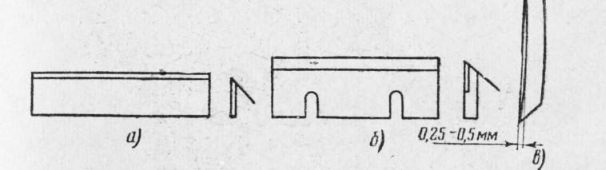
Rice. 1. Planing knives: a - thin; b - thick; in - deflection of the knife in width
The front edge of the knife should be smooth, polished; the back face can be smooth or corrugated. Corrugation contributes to a better grip of the knife with knife shaft. Knives with cracks are not suitable for work. Shells, rust are not allowed on the knives.
The cutting angle of the planer knives is 40°. Sharpening of knives is carried out in a knife-blade workshop on grinding machines; manually, you can only edit the knives with a whetstone.
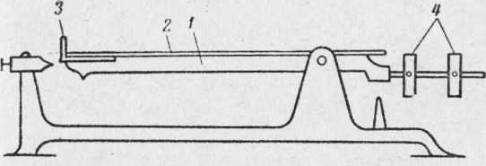
Rice. 2. Scales for balancing planer knives: 1 - balance beam; 2 - knife; 3 - emphasis; 4 - hinges
All knives mounted on the same knife shaft must have the same thickness and the same weight. The weight of the knives is checked by weighing them one by one. In addition, each knife must be balanced, i.e. balanced so that its center of gravity is exactly in the middle. The knives are balanced on special balancing scales (Fig. 80). The knife is placed on the yoke of the scales with the end close to the Stop and the scales are brought into balance with the help of a hitch. After that, the knife is turned over and placed close to the stop with the other end. If at the same time the balance of the scales is disturbed, then the knife is not balanced with respect to the axis of symmetry,
To equalize the weight of both halves of the knife and the weight of all knives of one head, grind off part of the metal from the butt of one or another knife. Less commonly, metal is welded onto the butt.
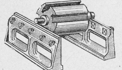
Knife shafts. Working shafts in planing machines are often called knife shafts, sometimes - knife heads, cartridges. The knife shaft can be solid, made from one forging and composite. At the composite shaft, the axis is machined separately and a knife cartridge is tightly mounted on the dowels on it.
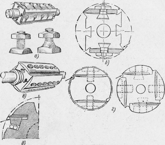
Rice. 3. Knife shafts: a - square shaft and bolts for fastening knives; b - fastening on a square shaft of thick knives; in - fastening on a square shaft of thin knives with the help of overlays; g - the transformation of a square knife shaft into a round one by means of segmented overlays; e - fastening of knives in round shafts (arrows show load breaking slopes)
Knife shafts are square and round.
Square shafts (Fig. 3, a) have longitudinal grooves of a T-shaped or trapezoidal section on their faces, into which bolts are inserted for fastening knives. The type of bolts is shown in fig. 3, a, fastening - in fig. 3b. When installing thin knives, overlays are used (Fig. 3, c).
The main disadvantage of square shafts is that during their rotation between the shaft and the edges of the desktop, at each turn, significant distances are formed that are dangerous, since the machine operator can get into these gaps with his fingers. In open planers, square knife shafts are not allowed. Other disadvantages of square shafts are as follows: 1) the knives are fixed only in places where the bolts are placed, therefore, vibration (trembling) of the knives during operation is possible in the gaps between the bolts; 2) no more than four knives can be mounted on the shaft. To eliminate the squareness of the shafts, a segment-shaped lining is used under the bolts (Fig. 3, d).
Solid-machined round shafts are the safest. To fasten knives on the side surface of these shafts, there are longitudinal grooves into which knives and trapezoidal clamping inserts with screws are inserted (Fig. 3, e). This method of fastening knives is quite reliable, excluding the possibility of the knife and the liner flying out of the groove during operation, as well as the vibration of the cutting edge, since the knife is evenly clamped along its entire length. In addition, this method allows you to install a significantly larger number of knives on a round shaft than on a square one.
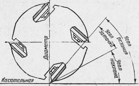
Rice. 4. Determining the sharpening angle, cutting angle and angle of the planer knife inserted into the cutter shaft
To form a loader, a slope is made in square shafts in front of the cutting edge of the knife, and a segment-shaped longitudinal recess is made in shafts with overlays. In round shafts, the slope is made in liners.
The knife shaft, whatever its shape, must be straight and balanced, i.e., have the same thickness (diameter), the same density and the same volumetric weight along the entire length.
The cutting angle of the planer knives mounted on the shaft is 50 - 65°, the slope angle is 10 - 15°. The angles are determined as shown in Fig. 4.
The cutting edges of all installed knives should be located at the same distance from the center of the shaft and evenly protrude above the edge of the chipbreaker by 0.5 - 1.5 mm. Tighten the bolts from the middle to the ends of the knife. After the machine has been running for 5 - 10 minutes, it is stopped and the bolts are tightened.
The balance of the shaft with knives is checked by turning it around the axis of rotation with stops. If the shaft remains completely immobile after stops, it is considered out of balance. An unbalanced shaft, as they say, “rolls down”, that is, it makes some additional rotational movement until it stops completely. Be sure to remove the drive belt before checking the balance.
A more accurate balancing of the shaft is done by turning it on the balancing knives (Fig. 5).
Rice. 5. Cutter head on balancing knives
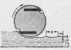
Rice. 6. Planing with rotating knives: a - wavelength; b - ridge height
To check the correctness of the installation of the knives in height, an accurately cut ruler is brought to the edge of any one knife and the knife shaft is rotated. If at the same time the cutting edges of all knives do not cling to the ruler and the gap between them and the ruler remains the same, it is considered that the knives are set correctly in height.
Planing with rotating knives is different from planing with a hand tool. When planing with a hand jointer, for example, long continuous chips are obtained, when planing with rotating knives, short chips are cut in the form of a segment. In the material across its fibers, a cavity is formed at the site of the cut chip, which is commonly called a wave. The planed surface is wavy (Fig. 6).
The shorter the waves, the lower the ridges between them, the cleaner the planed surface. The cleanliness of planing (wavelength) depends on the number of revolutions of the knife shaft, the number of knives on the shaft and
material feed rate. The higher the number of revolutions of the shaft and the more knives on it, the cleaner the planing. Planers of previous designs did only 3000 - 4000 rpm, in modern planers the shaft makes 5000 - 6000 rpm; install 4 - 8 knives on it.
Reducing the feed rate increases the cleanliness of planing, but at the same time reduces labor productivity. Therefore, it is possible to reduce the feed rate only in exceptional cases, for example, when planing wood that is very frizzy, wood of valuable species.
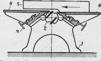
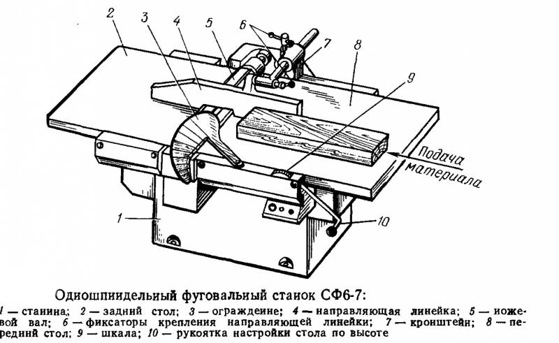
Rice. 7. Scheme of the design of the jointer: 1 - frame; 1 - knife shaft; 3 - screw for raising and lowering the plate; 4 - desktop; 5 - guide ruler
Often, wood processing is carried out by planing. Planing is a process with a straight-line feeding of a tree into the cutting zone, when the cutting plane, the cutting surface and the machined surface coincide. The planer has a shaft with knives that are mounted on a bed and move around its axis. In this case, the workpiece performs a reciprocating motion. The jointer is very popular. A similar woodworking machine has been used at home for the past few years. Industrial models of such equipment are quite expensive, but homemade jointers can also be made, which can also be used in wood processing.
Main knots
Before you make a homemade jointer, you need to create drawings and deal with the main elements that will be included in the scheme. Usually, planer consists of the following main elements:
- beds;
- shaft with a knife;
- roller;
- the electric motor from which rotation is supplied;
- several tables;
- tenacious horse.
The created drawing of a home-made jointer should contain information about the distance at which the electric motor with a roller and the shaft with knives are installed. The circuit determines how much the number of rotations at the output will be reduced and the power will be increased.

Manufacturing
We make a frame
The bed becomes the basis for the machine. You can do it yourself, taking into account the following points:
- Most of all, a metal profile is suitable for creating a frame for a homemade jointer. It is light weight and easy to dismantle.
- When creating a drawing, it should be taken into account that the structure must distribute the load and be stable.
- All elements must be firmly fixed. The mechanism installed on the frame, taking into account the material being processed, exerts a significant load.
- The elements are fastened together by welding or threaded connections. If you need a homemade jointer to be mobile and transported if necessary, then you need to choose threaded connection. Welding is more reliable, but the design will be non-separable.
It should be borne in mind that the planer must be installed level. Therefore, when connecting all the elements, the level is strictly maintained.
Installation of a shaft with knives
A homemade jointer, like the industrial version, has a drum with knives on the surface, which, when rotated, removes the tree from the surface of the workpiece. The features of the installation of this element include:
- The drum is a mechanism that consists of two bearings, a blade and a central shaft to which rotation is transmitted.
- It is almost impossible to make blades with your own hands, since this requires a lathe and a vertical milling machine.
- The drum is mounted on the frame through bearings that have special fasteners.
- The mechanism with blades must be firmly attached to the base, since it is on this node that all the load is concentrated.
- A pulley for a belt must be installed at the end of the output shaft. However, you can make it yourself. The profile of this element should be selected according to the profile of the belt.
Many drawings have a scheme in which the blades on the axis are installed in the central part of the frame.
Table
The design has two tables, which are located on opposite sides of the drum. The complexity of their manufacture lies in the fact that the fastening mechanism must rigidly fix the surface. Planer handmade must have smooth surface tables. This is due to the fact that the supply of the tree will be carried out at strong pressure. If there is strong friction between the table and the workpiece, then processing is significantly more difficult.
In addition, it should be taken into account that the table must be level relative to the drum with blades. In this case, the height must be adjusted, for which it is installed special mechanism. With your own hands, you can create a similar adjustment mechanism by using a threaded connection.
Another important point it can be said that the table should have a width and length according to which workpieces will be fed. You can also make a collapsible mechanism with your own hands.
Drive motor installation
The rotation of the cutting tool comes from an electric motor. When considering recommendations for installing an electric motor, consider the following points:
- It is quite important to choose the right type of electric motor and its power. A planer homemade jointer can remove a fairly large layer of material in one pass. For domestic use, an electric motor with a power of more than 1 kW is suitable. Recently, models that are powered by 220 V have become very popular.
- The machine will work correctly if the motor pulley is in the same plane with the drum pulley. This is quite difficult to do, you need to use measuring tools and a level.
- It is important to choose the right pulley diameters. The difference in diameters allows to reduce the number of revolutions at the outlet, which significantly increases the traction force.
- The belt must be well tensioned. It should be borne in mind that they are produced according to established standards and have a certain length. Therefore, the distance between the pulleys is carefully measured.
- It is recommended to create seat on a homemade jointer for an electric motor with the ability to adjust its position. This will allow the belt to be tensioned when its length has increased due to wear.
Particular attention is paid to the safety of a homemade jointer. The electric motor of the machine must not be grounded through the bed, as under certain circumstances electric shock may occur.
hard stop
Last constructive element, which you can also create with your own hands, is a hard stop. It is necessary to maintain the rectilinear movement of the workpiece along the table. To do this, the craftsman also exerts a transverse force while feeding the workpiece in the longitudinal direction. The stop is installed on the far edge of the table, with your own hands it can be made from an ordinary piece of wood, for which it is enough to improve the quality of the surface for a minimum degree of roughness.
In conclusion, we note that a homemade jointer is made as safe as possible, since it has a large number of rotating elements. To do this, you can create a special casing from wood or plastic that will cover the electric motor, rollers and belt. You also need to pay attention to the fact that a homemade jointer must have a rigid installation.
If you find an error, please highlight a piece of text and click Ctrl+Enter.
Used for processing flat and shaped surfaces: inclined, angular, horizontal and vertical. Homemade devices most often combined on one shaft circular saw and cutting device. This is a very dangerous option, so it is preferable to spend more effort and install two different shafts. But first, you should familiarize yourself in more detail with the device of the wood planer for the home.
Functions and working principle of planers
The planing of ruled and shaped parts made of wood is not the only function of the machine. On it, grooves, recesses, grooves and ledges are brought to smoothness, products are processed along a closed contour. The purpose of the mechanism is to bring the part in thickness and smoothness.
There are double-sided machines that process two surfaces in one pass. They are most widely used in the production of parquet for the house, solid wood furniture boards. After sawing, the workpieces are fed to a planer, where they are brought to the required smoothness. For processing hardwoods, special knives are installed.
The working surface moves back and forth. A board is fixed on it. Cutters are installed in the calipers with their own hands. The workpiece is pulled between the cutters, removed upper layer. Processing is carried out cyclically until the required thickness of the part is reached.
Longitudinal planing devices contain a mechanism that creates a reciprocating movement of the table top and movement of the working body vertically or horizontally.
The machine is controlled by its own hands with the help of knobs and buttons. Their placement should be as convenient as possible; this should be provided for in the drawings of the home-made apparatus.
An electric motor is installed in the equipment, the most advanced models are equipped with a gearbox with a smooth change in speed. The planer is the basis for universal grinders and planers with boring.
The device of planing machines
The main elements of the planer:
- electric motor;
- knife shaft;
- rollers;
- working surface.
The working surface consists of two parallel halves, between which a knife shaft is installed, the purpose of which is to remove the upper layer of the workpiece. The board is fed for cutting manually or automatically. The board is fixed on the working surface with rollers.
The machine allows you to set the thickness of the layer to be removed with your own hands at home. For this, a special high-precision mechanism is provided.
Base - homemade frame is made of metal corner 50x50 mm. The width of the base is determined by the gap between the shaft bearings (support). The body is bolted to the frame. Metal rods act as homemade crossbars.
With their own hands, the working surface is made of two parts: fixed and movable. Both parts are superimposed on a welded frame made of a metal corner 25 x 25 mm. The length of the frames should be 5 cm less than the length of the work surface. The width matches the width of the table. The working surface is made of a sheet of metal 3 mm thick.
A do-it-yourself fixed frame of the table is welded onto racks from a rectangular pipe 40 x 10 mm. Installation of the fixed part of the countertop is carried out in the following order:
- with the help of wedges, it is set parallel to the base and shaft;
- the stand is welded to the base.
The mobile part of the tabletop is made in the form right triangle in section. In order to raise or lower the table relative to the shaft, a screw connection (lanyard) is provided.
The tabletop is attached to the frame with countersunk screws on gaskets. A cotter pin is attached to the fixed corner, which does not allow a height change of more than 3 mm.
To stop the workpieces, a ruler is provided, which makes it possible to change the inclination of the support.
Homemade planer
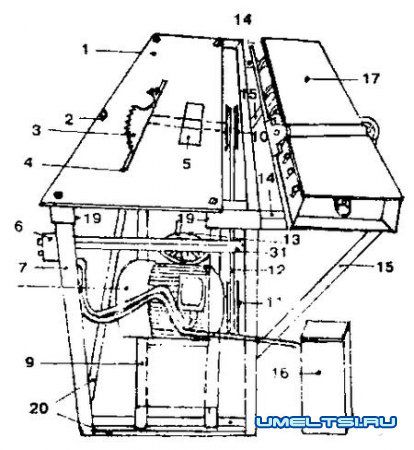
View of the machine from the end: 1 - plate 110x5x1 cm; 2 - fixing bolts; 3 - saw; 4 - groove for the saw; 5 - hole for the cutter; 6 - push-button PIV machine; 7 - legs; 8 - engine; 9 - lower frame; 10 - saw shaft pulley; 11 - electric motor pulley; 12 - wedge-shaped belt; 13 - wheel of the tension mechanism; 14, 15 - planer clamps during downtime; 16 - capacitors working and starting; 17 - planer; 18 - shaft for lifting frame; 19 - recess in the corner for the planer during operation; 20 - lower corners; 21 - corner for fixing the planer
The presented do-it-yourself safety design is equipped with two electric motors and a pair of shafts. Engine power 5.5 and 3.5 kW, give out up to 3000 rpm. A milling drum is put on the first shaft, a circular is put on the second. Due to the fact that the engine can move in the grooves, the working body rises and falls.
On such a machine, you can work on wood at home with circles up to 50 cm in diameter, reaching a speed of up to 4500 rpm. Some craftsmen “accelerate” the motor even up to 6000. However, the planer shaft must first be carefully machined, milled and balanced. Otherwise, the shaft will "beat". Parts up to 6 meters long and up to 2.5 meters wide are processed.
Construction details. Shafts can be interchanged with your own hands. It is not necessary to remove the frame to install the milling shaft. The saw is raised to its maximum height with the key. A pair of bolts is used to fix the frame on the eccentric. The saw and frame are lifted by eccentrics. Frame on which it is installed saw blade fixed with bolts.
A plate is attached to the lower part of the electric motor, moving in the grooves provided for this. The plate is driven by a wheel that changes the belt tension. This is useful, for example, for changing shafts. The planer is mounted on a holder, which is fixed with bolts.
Dimensions. Machine width 50 cm, height 80 cm, length - 110 cm compact machine is easy to place at home. For stability, do-it-yourself spacers are welded from the corner from the bottom and a metal corner 35 x 35 mm.
The video demonstrates the work of a homemade woodworking machine:


Mars space program
The history of the origin of zero What is the name of zero
Gloria planet (anti-earth) - exposing all revelations Is it true that there is a planet behind the sun
20 cases of alleged reincarnation
The secret of the "sun stones": how the Vikings got from Norway to Greenland almost blindly