K category: Joinery
Planing machines
The blanks obtained after cutting are usually processed for planers. Planers are planers for planing into a corner, planers for making edges parallel and four-sided planers.
Jointers
Jointing machine SF6-3 (Fig. 1) is designed for planing (joining) the surfaces of boards, boards and bars along the plane, as well as narrow edges (edges) at a right or other specified angle to a wide edge.
Rice. 1. Jointing machine SF6-3: 1 - electric motor, 2 - rear plate of the desktop, 3 - guide ruler, 4 - handle of the front plate height indicator, 5 - fan guard, 6 - front plate of the desktop. 7 - starting device, 8 - knife shaft, 9 - frame
The jointer consists of a frame, two cast iron plates, forming a working table, a knife shaft (cutter head), planer knives and drive.
The front (first along the material) plate of the machine serves to guide the material before planing, and the rear plate to guide the material during the planing process. The front plate is set 1.5-2 mm lower than the back plate, i.e., by the thickness of the chip being removed.
Each table plate can be set to the required height. Adjustment of the front plate in height is made by a handle on which there are height marks. The rear plate is adjusted with a screw and nuts.
A cutter shaft 8 is located between the plates. The cutting edges of the knives mounted on it are flush with the surface of the rear plate. At the ends of the plates facing the knife shaft, steel pads-sponges are attached flush with their surface, designed to protect the plates from abrasion and spalling, as well as to reduce the gap between the knives and plates and support the fibers when cutting chips. The knife shaft is driven by an electric motor through a V-belt drive. The knife shaft is closed from above by a fan protection.
The machine is equipped with a removable guide ruler, which can be moved across the table, set at the required angle or tilted up.
In addition, the machine has a brake device for quick braking of the knife shaft after turning off the motor.
Usually, three types of work are performed on a jointer: face jointing, face jointing and one edge jointing, and face jointing and two edges jointing. In addition, it is possible to remove sags on boards and frames with simultaneous alignment of the plane, trimming boxes to size, jointing plywood edges, etc. Before jointing, the part must be placed with the concave side down for greater stability.
Submission for jointers in most cases it is done manually.
At the same time, narrow parts are planed simultaneously in several pieces. The jointing of the edges of thin plots is carried out in batches. When working on a machine with a conveyor feed, the parts are fed end to end.
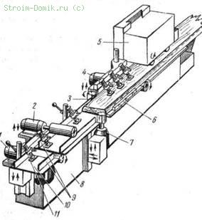
To facilitate and ensure the safety of work, it is now increasingly used special devices, serving for automatic feeding of material, the so-called automatic feeders (Fig. 2, a, b). Their use increases productivity by 1.5-2 times.
The autofeeder is mounted on a stand that is mounted on the machine and can be installed in any position with respect to the work spindle, table or machine guide.
The currently available universal automatic feeders can be used on planers, circular saws, milling, band saws and grinding machines and provide mechanization of feed on these machines, which are usually produced with manual feed.

Rice. 2. Universal automatic feeder: a - installation for feeding with a top clamp, b - installation for feeding with a side clamp
The main defect of planing on a jointer is the non-straightness of the planed surface as a result of weak or uneven pressure on the workpiece. In addition, defects are often observed in the form of protrusions up to 1-1.5 mm deep, scuffs (when processing against the layer). In these cases, there is a need for subsequent selective cleaning, which is carried out on the "Lilliput" jointing machines.
Workpieces should be placed near the machine so that the machine operator does not have to make unnecessary movements. The layout of the organization of the workplace at the jointer is shown in fig. 3.
Safety precautions when working on jointers
1. The distance between the edges of the desktop overlays and the surface that the knife blades describe should be no more than 3 mm.
2. Working part The slots must be closed with an automatically operating fence that allows all work to be performed on the machine and opens the knife slot only to the width of the workpiece. The non-working part of the slot behind the guide bar must be completely closed at all positions of the guide bar.
3. When planing parts shorter than 400 mm, narrower than 50 mm and thinner than 30 mm, when manually feeding the material, push blocks should be used.
4. Application knife shafts square shape and overlays to give square shafts a cylindrical shape is prohibited.
5. It is allowed to let the knives out of the shaft by no more than 3 mm.
6. The surface of the rear plate must match the cutting edge of the knives.
7. Shape planing and selection of quarters on a planer is prohibited.
Thicknessing machines
Thicknessing machine SR12 (Fig. 4, a, b) is designed for one-sided planing of a part parallel to the jointed side to a specified thickness.

Rice. 3. The scheme of the rational organization of the workplace at the jointer: 1 - unplaned parts, 2-place of the machine operator,. 3 - planed details
The table (Fig. 4, a) of the thicknessing machine consists of one solid plate, and the knife shaft is located above the table. The table moves in height to set the required distance to the cutting edges of the knives. The thickness of the removed layer of material at the largest planing width should not exceed 2 mm.

Rice. 4. Thickening machine SR12: a - general form: 1 - knife shaft motor, 2 - starting device, 3 - safety cover, 4 - work table, 5 - feed motor, 6 - bed; b - diagram of the working part: 1 - worktable, 2 - workpiece, 3 - safety hangers (claws), 4 - corrugated feed roller, 5 - cap, 6 - knife shaft, 7 - rear pressure block, 8 - visor above the roller, 9 - smooth feed roller, 10 - lower guide rollers; c - sectional feed roller
Material feeding on planer machines is done mechanically. The feed mechanism consists of two pairs of rollers. The first pair is located in front of the knife shaft, and the second - behind the shaft. The upper drive rollers are driven by an electric motor 5 through a gear train. The lower rollers (guides) are positioned exactly below the upper rollers, freely mounted and driven by the feed material.
The lower rollers protrude 0.2-0.3 mm above the table surface. The upper front rollers are made corrugated so that the material does not slip. Install them 2-3 mm below the surface of the material being fed. The corrugated feed roller is made from separate sections (Fig. 4, c). This allows the simultaneous processing of several workpieces of different thicknesses (within 4 mm).
The upper rear roller is made smooth so as not to spoil the planed surface of the workpieces. Install it below the cutting edges of the knives by 1 mm.
There are hangers in front of the corrugated roller, the purpose of which is to prevent parts from flying back out of the machine.
The knife shaft is closed from above by a massive enclosing cap, which is also a device for removing chips into the exhaust device (exhauster).
The front edge of the cap is located very close to the radius of rotation of the knives. It presses the bar, preventing its vibration, and also serves as a support for the wood fibers at the exit point of the knife and prevents the possibility of chipping.
When setting up a thicknessing machine, it is necessary to ensure that the desktop is installed without distortion, and check the correct position of the lower and upper rollers.
The productivity of the machine depends on the feed rate and the number of simultaneously processed parts.
Shields with tips or bound frames are fed into the machine obliquely, since with a straight feed, planing will occur across the fibers and the surface will turn out to be rough and chipped at the edges.
Safety precautions when working on planer machines
1. Corrugated rollers should not have cracks, knocked-out ribs and a worn surface.
2. The top rollers must be fully protected from the working side.
3. The length of planed parts is allowed not less than the distance between the front and rear upper rollers plus 50 mm.
4. Simultaneous planing of two or more parts of different thicknesses with a continuous feed roller is prohibited.
Quadruple planers and moulders
To combine the operations of planing the face and edge, three
- Planing machines
Lumber, or blanks, coming after cutting for further processing, as a rule, have risks, roughness, warping and other defects that are easily eliminated during planing.
When planing (along with the elimination of these defects), it is necessary to obtain an accurately adjusted (basic) surface so that, focusing on it, it is possible to align the rest of the surfaces and have parts of the correct shape.
A regular-shaped part is obtained if, during processing on a planer, it occupies a certain position in relation to the cutting tool and guides (table, ruler), while the accuracy of the part depends on how well the face and edge adjacent to the mounting devices are aligned (line). Planing usually results in smooth and profiled surfaces.
For planing, planer, planer and four-sided planers are used.
Purpose jointers - alignment of the surface of the part along the plane and into the corner. When planing on a planer, a base surface is created on the parts, which is necessary for their further processing on machines. Our industry produces planers with manual and mechanical feed. Machines with manual feed include jointers SF4-4 and SF-6; to machines with mechanical feed - double-sided planer S2F-4 with automatic feeding.
Jointers with manual feed are widely used in the production of joinery and can be recommended for enterprises with a small volume of production - up to 100-150 thousand m2 of joinery per year. At large volume production, jointing machines with mechanical feed should be used, as the most productive and safe in operation.
Planer with automatic feed, used for simultaneous planing of the face and edges of workpieces, is a cast-iron bed, on which, on eccentric supports, the front and rear plates of the desktop are located. Between the plates there is a horizontal knife shaft with a diameter of 125 mm, a length of 410 mm, rotating in ball bearings. The knife shaft is driven by an electric motor with a power of 2.8 kW through a V-belt transmission. There is a guide line on the plates.
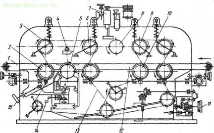
Rice. 1. Scheme of a double-sided planer: 1 - fixed part of the ruler, 2 - fixing screw, 3 - bracket, 4 - rack, 5 - V-belt transmission, 6 - electric motor, 7 - screw adjusting the belt tension, 8 - plate for installing the electric motor, 9 - handle for mounting the bracket, 10 - eccentric for adjusting the installation of the movable part of the ruler, 11 - movable part of the ruler, 12 - cutter head, 13 - spindle
The size of the removed layer of wood is regulated by raising or lowering the front table with a handle with a height indicator. Adjustment of the position of the rear plate is made with a screw and a nut. In addition to the horizontal knife shaft, a vertical knife head is mounted on the machine, with which the edge of the workpiece is planed. The vertical cutter head is mounted on a spindle mounted on a special support. The drive of the spindle of the vertical cutter head is carried out from an electric motor with a power of 1.7 kW through a V-belt transmission.
Lumber, or blanks, coming after cutting for further processing, as a rule, have risks, roughness, warping and other defects that are easily eliminated during planing.
When planing (along with the elimination of these defects), it is necessary to obtain an accurately adjusted (basic) surface so that, focusing on it, it is possible to align the rest of the surfaces and have parts of the correct shape.
A regular-shaped part is obtained if, during processing on a planer, it occupies a certain position in relation to the cutting tool and guides (table, ruler), while the accuracy of the part depends on how well the face and edge adjacent to the mounting devices are aligned (line). Planing usually results in smooth and profiled surfaces.
For planing, planer, planer and four-sided planers are used.
The purpose of planer machines is to align the surface of the part along the plane and into the corner. When planing on a planer, a base surface is created on the parts, which is necessary for their further processing on machines. Our industry produces planers with manual and mechanical feed.
Machines with manual feed include jointers SF4-4 and SF-6; for machines with mechanical feed - double-sided planer S2F-4 with automatic feed.
Jointers with manual feed are widely used in the production of joinery and can be recommended for enterprises with a small volume of production - up to 100-150 thousand m2 of joinery per year. With a large volume of production, planing machines with a mechanical feed should be used, as the most productive and safe in operation.
A planer with automatic feed (Fig. 127), used for simultaneous planing of the face and edges of workpieces, is a cast-iron bed, on which, on eccentric supports, the front and rear plates of the desktop are located. Between the plates there is a horizontal knife shaft with a diameter of 125 mm, a length of 410 mm, rotating in ball bearings. The knife shaft is driven by an electric motor with a power of 2.8 kW through a V-belt transmission. On the plates there is a guide ruler 1, 11.
Rice. 127. Scheme of a double-sided planer:
1 - fixed part of the ruler. 2 - fixing screw, 8 - background matte, 4 - racks, 5 - V-belt transmission, 6 - electric motor, 7 - screw adjusting the belt tension, 8 - plate for installing the electric motor, 9 - handle for installing the bracket, 10 - eccentric to regulate the installation of the movable part of the ruler, 11 - the movable part of the ruler, 12 - cutter head, 13 - spindle
The size of the removed layer of wood is regulated by raising or lowering the front table with a handle with a height indicator. Adjustment of the position of the rear plate is made with a screw and a nut. In addition to the horizontal cutter shaft, a vertical cutter head 12 is mounted on the machine, which cuts the edge of the workpiece. The vertical cutter head is mounted on a spindle 13 mounted on a special support. The spindle drive of the vertical cutterhead is carried out from an electric motor 6 with a power of 1.7 kW through a V-belt transmission 5.
The supply of blanks and lumber to the horizontal knife shaft and vertical head is performed by an automatic feeder driven by an electric motor through a gearbox. The ADF can be moved both vertically and laterally. The machine of this design can be built into a semi-automatic line for processing bar parts.

Rice. 128. The scheme of the planer

Rice. 129. Devices for safe work on jointing machines:
a - fan-type fencing, b - clamping block; 1 - block, 2 - handle, 3 - workpiece
Working on cutting machines. The main task of processing on a planer is to obtain a completely flat and straight face and one side edge in such a way that they are at right angles to each other. During further processing on thicknessing, planing, molding, tenoning and other machines, these surfaces are basic - from their correctness and accuracy; depends on the quality of the parts. It should be noted; that if the workpiece has a curvature of the face and edges, then after processing on thicknessing and planing machines, these defects remain in the finished part, and on tenoning, drilling and grooving and other machines this leads to distortions of spikes, holes and sockets, which results in low quality products.
The scheme of the jointer is shown in fig. 128. Before working on the planer, it is necessary to inspect the workpiece 8, and carry out the processing from the concave side, directing it to the knife shaft 1 in such a way that there is no scuffing of the fibers from the oncoming oblique layer. It is necessary to feed the workpieces onto the knife shaft evenly, without jerks.
Curves of the workpiece should not be processed, since you still will not get a quality part. The planing of the workpiece must be carried out until a clean surface is formed without a gap. The quality of gouging on a jointer is checked as follows: jointed blanks are folded with machined edges or layers, if there are no gaps between them, then processing is considered sufficient
When working on the machine, safety regulations must be observed, since an open rotating shaft is very dangerous; the knife shaft must be equipped with a fan-type guard (Fig. 129, a), opening only during the passage of the workpiece and automatically closing after processing the workpiece. Short workpieces must be processed using a clamping block (Fig. 129, b). The machine should be adjusted in such a way that the gaps between the blades of the knives and the plates are minimal; in addition, the surface of the plates must be horizontal.
Thickness thicknessers are designed for planing parts to a given size in thickness and creating strictly parallel planes in them. There are single-sided thicknessers (SR6-6 and SR-12-1) for planing one plane and two-sided (C2R8-2 and C2R12-1) for simultaneous planing of two parallel planes.
The technical characteristics of thicknessing machines are given in table. thirteen.
|
Indicators |
bilateral |
Unilateral |
|
|
Maximum planing width |
|||
|
Product thickness in mm |
|||
|
The smallest length of the processed material in mm. |
|||
|
Cutter shaft diameter in mm |
|||
|
Number of revolutions of the cutter shaft |
|||
|
Feed speed in m/min |
Stepless 4.2-25 |
||
|
Number of knives |
|||
|
The total power of electric motors in ket. |
|||
|
Machine dimensions (length X width X height) in mm.... |
2025X2900 X X1800 |
1615x1585x1550 |
1100X1380XX1560 |
|
Weight in kg.......... |
|||
Thicknessing machine SR6-6 is used for one-sided plane planing of boards, bars and shields up to 630 mm wide and 5 to 200 mm thick.
The machine is a cast-iron bed, on which a table, a knife shaft, a feed mechanism and drive mechanisms are placed. The machine table can be moved up and down by a lifting mechanism driven by an electric motor. The table is set in height depending on the thickness of the workpieces being processed.
The knife shaft rotating in bearings is set in motion through a V-belt transmission from an electric motor. From the knife shaft, through a V-belt drive and a four-speed feed box, the material feed mechanism is driven.
The material is fed by two upper and lower rollers, of which the upper, front, has a sectional design (Fig. 130). Rings with a corrugated surface 3 with rubber fingers 4 are put on the sectional shaft 5. The presence of rings and rubber fingers allows the machine to simultaneously process workpieces with uneven thickness within 4 mm.

Rice. 130. Scheme of the device of a sectional corrugated roller of a thicknessing machine:
a - scheme for feeding blanks, b - design of a corrugated roller; 1 - bearing, 2 - rack for mounting the clamping device, 3 - ring, 4 - rubber fingers, 5 - shaft for installing rings
The lower smooth feed rollers, on which the processed bar rests, protrude from the plate to a small height (2 mm), and this protrusion value can be adjusted with screws located at their ends. For efficient operation of the machine, the rollers must protrude to the desired height and equally at both ends.
A hinged massive metal cap is installed above the knife shaft, the front sharp edge of which rests on the material being cut in front of the knives of the rotating knife shaft. By pressing the stones against the table to reduce vibration, the sharp edge of the hood acts as an additional chipbreaker for quality gouging. The height of the pressure cap is adjusted by the support adjusting bolts.
In front of the feed rollers, anti-blowout “claws” are installed to prevent the possible ejection of thinner bars back by the knives. The machine is equipped with a device for pointing and jointing knives directly on the machine.
Thicknessing machine SR-12-1 is designed for one side planing of wooden panels, window and door parts up to 1200 mm wide, as well as for cleaning the surface of assembled window sashes and door panels. In one pass on the machine, a layer of wood up to 2 mm thick. The design of the machine allows you to simultaneously plan several workpieces with uneven thickness up to 4 mm.
Rice. 131. Scheme of the device of the double-sided thicknessing machine S2P8-2:
1 - mobile table located after the lower shaft, 2, 3, c, 9, 10 - feed rollers, 4 - clamp, 5 - lower knife shaft, 7 - sharpening device, 8 - upper knife shaft, 11 - handwheel of the lifting mechanism and lowering the table, 12 - table, 13 - chain, 14 - handle, 15 - handwheel of the mechanism for moving the rear table in height
Thicknessing double-sided machines are designed for simultaneous planing of carpentry parts to a given size in thickness. On machines, several parts can be planed simultaneously with a difference in thickness of up to 4 mm. The scheme of the double-sided raismus machine С2Р8 = 2 is shown in fig. 131.
Thicknessing machine S2P8-2 is designed for double-sided planing of products or panels up to 800 mm wide. On the frame of the machine there is an upper block with upper feed rollers 3, 6, 9 and an upper knife shaft 8. There is also a table on the frame on which the lower knife shaft 5 is installed, which is located behind the upper knife shaft in the course of processing parts. Table 1 can be raised or lowered through a mechanism driven by a 1 kW electric motor, or manually. The feeding of the material for processing is carried out by the feed rollers through the gearbox of the four-speed electric motor. To quickly stop the knife shafts, the machine is equipped with electromagnetic brakes.
Thicknessing machine S2P12-1 is approximately similar to the machine type S2P8-2, but has a planing width of 1250 mm. Both machines are equipped with devices for pointing and jointing of knives.
Work on planer machines. To obtain parallelism of opposite layers or edges, the workpieces are planed from one or both sides on thicknessing machines. The processed bars (blanks) are placed on a horizontal table and the feeder (rollers) is directed to a rotating shaft on which the knives are located. In single-sided thickening machines, the knife shaft is located on top, and in double-sided ones, on top and bottom of the workpiece. To improve the cleanliness of planing, the machine is equipped with clamping pads, which, by their pressure on the workpiece, protect it from vibration.
Workpieces that have been processed on planer machines are fed into the thicknessing machine. When processing workpieces without preliminary jointing, i.e. warped, low-quality parts are obtained. This is due to the fact that under the pressure of the feed rollers, the workpiece is first leveled, and when leaving the machine, it again takes on its original warped shape.
When working on a thicknessing machine, it is necessary to ensure that the working width of the machine table is used as fully as possible - for this, the maximum number of bars - blanks to be processed are laid at the same time. The workpieces are fed into the machine end to end, i.e. end to end. Bars with pronounced defects should not be fed into the machine, since after planing the bars will be rejected.
The planed bars should not have pins, tears, hairiness, risks (convex). The presence of hairiness and scratches indicates that the blanks were planed with blunt knives. The waviness on the surface of the planed bars is a consequence of the clogging of chips between the knife and the chip breaker. Pins or tears in the bars are formed as a result of the fact that the pressure block is poorly adjusted (pressed).
Before working on the machine, you should check how correctly the knives are installed and well sharpened. The planes of the knife shaft, on which the knives are applied, must be clean, without potholes and dents. The edge of the chipbreaker must be strictly straight and not have potholes. It is also necessary that the machine table has a clean horizontal surface without potholes. The feed mechanism (grooved rollers or sectional and smooth ones) must not be warped or bent.
To prevent the shaft from beating, balanced knives of the same weight, thickness, width and length are installed on the neg.
When working, you must strictly follow the safety rules. The length of the planed parts should be 50 mm more than the distance between the axes of the feed (front and rear) rollers. In order to prevent the bars from being thrown back, the machine is equipped with sectors (retaining claws); the feeder and rotating parts of the machine (shaft, drive, etc.) must be protected; it is forbidden to clean, adjust and repair the machine on the go
Four-sided planers C10-2, C16-4 and C26-2 are designed for planing carpentry parts from four sides with the creation of a profile. Machine tools with 4-5 working spindles are produced; They have lower and upper horizontal knife shafts, with which the parts are planed, as well as vertical (right and left) knife shafts, which are used for smooth and profile planing of edges.
Rice. 132. Four-sided planer C10-2:
1 - support of the fifth lower moulder spindle, 2 - support of the upper horizontal spindle, 3 - right vertical spindle, 4 - support of the lower horizontal spindle, S - support of the feed mechanism, 6 - horizontal clamping device, 7 - support of the left vertical spindle, 8 - frame, 9 - guide lines, 10 - base plates, 11 - clamp
On four-sided planers (after vertical knife shafts) there is a fifth additional knife shaft, designed for profile planing of a plate or for sawing planed parts into several parts. In the presence of the fifth knife shaft on the machine, it is possible to plan two or more parts from one workpiece at the same time, cutting them directly after gouging. At many enterprises, using such a machine, they plan at the same time two bars of window casings, etc.
On planers, the work spindles are arranged in such a way that it is more convenient to install the tool. The supports in which the spindles are mounted can be moved both vertically and horizontally. The supply of materials for planing is carried out by the feed mechanism, and on machines operating at a feed rate of more than 25 m / min, there is a special feed table that ensures the continuity of the supply of material to the machine. The scheme of the four-sided planer C10-2 and its individual components are shown in fig. 132.
The C10-2 four-sided planer, designed for planing from four sides with the creation of a profile, is a cast-iron prefabricated frame on which the roller-caterpillar feed mechanism, guide rails, clamping mechanisms and knife shaft supports are located. The presence of the 5th shaft on the machine allows, along with planing, sawing of planed parts along. The machine mainly processes details - bars of window sashes, glass layouts, flashings, ebbs, lining for panel doors, etc.
The C16-4 four-sided planer is almost the same as the C10-2 machine, except that this machine can plan parts up to 160 mm wide (instead of 100 mm on the C10-2 machine) and from 10 to 80 mm thick (instead of 6- 50 mm). It is intended for planing from four sides with the creation of a profile for the following parts of joinery products: bars of cabinet boxes, layouts, facings, flashings, bars of window sashes, skirting boards, fillets, platbands, etc.
The four-sided planer C26-2, designed for planing from four sides with the creation of a profile, is a more powerful machine - it can process parts with larger sections.
The machine is a cast-iron prefabricated frame with a roller-caterpillar feed mechanism and base plates, calipers with cutting heads, clamping mechanisms and guide lines located on it. The machine has five cutter heads arranged in the following order: lower horizontal, right and left vertical, upper horizontal and lower moulder. Instead of a molding head, a vertical spindle support can be installed.
On the machine S26-2, they process mainly bars of window and door frames, bars of bindings, boards of a clean floor, etc. In addition, along with planing, this machine can saw longitudinally machined parts.
Cutting tool for planing. For planing, a cutting tool is used in the form of knives and milling cutters, which are mounted on shafts. Knife shafts are round (for fastening thin knives) and square (for fastening thick knives). Square shafts are used only in planers and four-sided planers; they must not be used on hand-feed planers as this may cause injury.
Depending on the design of knife shafts it is possible to fasten from 2 to 32 knives. Thin knives are attached to the knife shaft with pads pressed against the shaft with bolts or wedge-shaped liners. The last method of fastening is the most durable and widely used.
When planing, flat knives (GOST 6567-61) with a straight cutting edge are used (Fig. 133); for profile planing - shaped knives; for smooth and profile planing - cutters (cone cutters).
Shaped knives for profile planing have recently been replaced by milling cutters.

Rice. 133. Flat knives with a straight cutting edge for wood milling:
a - without slots (thin knives), 1 - rear face, 2 - outer face, 3 - front face, 4 - longitudinal face, B - cutting edge, 6 - end face; b - with slots (thick knives): L-length B - width
Flat knives with a straight cutting edge are used for planing on jointers, thicknessers and four-sided planers. Thickness of knives 3 and 10 mm. Knives with a thickness of 3 mm are used for planers and four-sided planers with a knife shaft for four or more knives; knives 10 mm thick - mainly for square shafts of planers and four-sided planers. In the plane of such knives, cuts are made for mounting bolts.
Thick knives (10 mm) - two-layer, the main part of the knife is made of mild steel, the welded (cutting) part is made of quality steel 2.5-3.5 mm thick. The length of thick knives is from 40 to 310 mm, the width is from 100 to 125 mm.
Thin knives (3 mm) - single-layer, without slots, are made of high-quality steel. Length of thin knives - from 30 to 1610 mm, width - 25-45 mm.
Before installing the knives on the machine, they should be well sharpened and balanced so that they have the same length, width, thickness and weight. Balancing of knives is carried out on a special device or on a balancing scale; the difference in weight of paired knives is allowed no more than 0.5%. In addition, the knife shaft on which the knives are attached and the fasteners must also be balanced.
When installing the knives on the shaft, it is necessary to ensure that they fit snugly against the supporting surfaces, paying special attention to the tightness of the front edge of the knife to the edge of the chipbreaker. The knives must be installed in such a way that their cutting edge protrudes beyond the edge of the chipbreaker by no more than 1 mm. Fasten (tighten) the knives with bolts alternately, starting from the middle of the shaft to the edges.
Milling cutters are a tool that has become widespread in the production of joinery. The cutter has 4-6 cutters, its installation is very simple, it is safer to work with it than with knives. The quality of planing when working with cutters is much better than when working with knives. In the production of joinery and building products, mainly end and shell cutters are used: end mills - when working on milling and tenoning machines; mounted - on planers and milling machines. Distinguish solid (profile) and compound shell mills. Solid cutters are used little, since after each sharpening they break the tooth profile; composite - are widely used for precise processing of profile parts.
Compound cutters are a set of cutters fastened with pins; as a result of adjusting one cutter relative to another, the angular parameters are preserved, therefore, after sharpening, the profile of the part remains unchanged. Mills are issued according to normals. The diameter of the cutters is from 80 to 180 mm, the number of teeth is from 4 to 8.
Angular parameters: y-35°-20° - rake angle; p=60°-45°-pointing angle; a=10°-15° - back angle.
For processing the right vestibule of window sashes, a single cutter (Fig. 134) with a diameter of 160 mm with four teeth is used.
Composite cutter for processing the groove of a door leaf lined with hardboard (Fig. 135) consists of three cutters connected by pins. The knives are fixed to the cutter body with screws 1 and a wedge 3. The cutter has a durability that is 15-20 times higher than that of conventional cutters. The cutter body and knives are made of grade 45 steel, the blades are made of VK-15 alloy.
Work on four-sided planing machines. A four-sided planer usually has two or three horizontal working shafts and two vertical ones.

Rice. 134. Cutter for processing the right vestibule of window sashes
Knives mounted on one working al must have the same weight, length,

Rice. 135. Composite cutter for processing the groove of a door leaf lined with hard fiberboard: 1 - screw, 2 - knife, 3 - wedge, 4 - hard alloy plate, 5 -
Cutters mounted on vertical shafts must be well balanced and sharpened. When installing knives and cutters, it is necessary to strive to ensure that the loads on the knife shafts that occur during planing do not exceed the permissible ones, i.e., so that chip removal is as minimal as possible.
In four-sided planers, all cutting heads and the feed mechanism are enclosed. Knife shafts and heads must be round, except for those knife shafts that are closed with blank casings. Fastening of knives in heads and shafts must be reliable and predominantly wedge. The feed mechanism of the machine is blocked with the cutting heads in such a way that the feed cannot work before they start.
Clamping mechanisms (roller, block) are installed in such a way that the processed bar can freely pass into the machine and not vibrate at the same time. The feed mechanism (upper feed rollers) is adjusted so that, when lowered, their height corresponds to the thickness of the bars after planing; the lower feed rollers usually protrude above the tables by no more than 1.5-2 mm.
Before work, they carefully check the fastening of knives and cutters, after which they alternately start up horizontal and vertical shafts, then control bars, and only after inspection and measurement (if the machine is set up correctly) they start working.
The material (bars, boards) must flow into the four-sided planer continuously, without breaks, i.e. end to end. Do not submit bars with rot and other defects, as well as with metal inclusions (nails, etc.). It is strictly forbidden to advance a stuck block with a blow. It is necessary to ensure that bars and boards of the same thickness and width are fed into the machine, that is, of the section for which the machine is configured for gouging.
In the process of work, it is necessary to periodically check the quality of the planed bars; if defects are found, the machine should be stopped, adjusted, and only then continue to work. The feed rate is chosen according to the given mode of operation. Short bars must be planed in multiple sizes, followed by trimming them. When working on the machine, it is necessary to strictly observe the safety regulations. It is forbidden to clean, lubricate and adjust the machine on the move. After finishing work, the machine should be stopped and cleaned of sawdust and chips.
Price: 150,000 rubles
The sba-200 machine is designed for planing boards and timber up to 260 mm wide.
The machine performs planing and chamfering.
Get a free consultation or place an order:
Sales Contacts:
Telephone: 8 800 100 95 12
(Free call within Russia)
Email:
Manufacturer:
Woodworking equipment plant ENERGOTEH-ALTAI
Guarantee period:
The warranty period for this equipment is 1 year.
Specifications:
Product description:
The machine is designed for planing timber or boards up to 260 mm wide.
There are two working units on the machine, one for planing, and the second for chamfering if necessary. The workpiece is fixedly fixed on the guides. The movement of the machine is carried out manually.
One of the most widely demanded and popular elements in woodworking enterprises is the sba 260 beam planer. The use of this unit can significantly speed up the work with wood and increase the productivity of the enterprise.
Wide range of uses
Today it is difficult even to imagine the production of wood products without its preliminary planing. This procedure involves processing the boards in such a way that, after completion, the workpiece corresponds to the selected size. At home, hand tools will be quite enough, but for logging production you need reliable, namely professional machine for planing. Unlike hand tool, automatic planers have the following characteristics:
- high productivity - there are machines of various capacities, but the sba 260 machine guarantees a large output of planed timber in a short period of time;
- cutting accuracy - when the machine is working, the dimensions finished products match up to a millimeter;
- excellent quality of planed material - all blanks have smooth surface;
- full automation of the process - on a production scale it is much more profitable, since the use of such a unit provides a large yield of planed product.
In addition, planers are characterized high level safety, which makes this equipment incredibly in demand for modern production.
The design and purpose of the device
The machine for planing timber sba 260 is used in production for processing timber and boards up to 260 mm wide, and the length of the raw material should not exceed 6000 mm. A similar machine for cutting wood is characterized by the presence of two working units. The first of them is planing - for processing boards, and the second node is intended for chamfering, if necessary. The cutting process is absolutely safe and proceeds quickly, since the workpiece is securely and immovably attached to the guides of this unit.
How to make the right choice
When buying a planer for production, you need to carefully study the characteristics and weigh the pros and cons. After all, the efficiency of work depends on how correctly the machine is selected or. The width should be taken into account - this is the maximum allowable width of the processed board, and the depth of planing - how many millimeters of material are cut off with knives in one go. You should also consider how many boards will be processed. Based on this, you can purchase a household or professional planer.
Planing machines are indispensable in modern production and in many private households. In order for the purchase to be rational and profitable, you should address such questions only to a respectable and reliable store. You can also buy machines from our dealers in Ufa, Krasnoyarsk, St. Petersburg, Yekaterneburg, Moscow and other 50 cities in 7 countries of the world.
Planing is the process of removing layers of metal from flat surfaces of workpieces. It is used along with milling, but differs in a different kinematics of the movement of the working tool: if the cutter performs a rotational movement, then the cutter on the planer is reciprocating. On such equipment, grooves and grooves are sometimes also performed.
Varieties
A planer for metal can be a longitudinal planer or a cross planer. The principle of processing blanks on these varieties is fundamentally different. Longitudinal planers are designed for processing relatively short surfaces, therefore, in them, the movement receives a table to which the workpiece is attached, while the cutter is installed in the cutter head of the caliper and does not move relative to the machine bed. In a cross-cutting machine, the opposite is true: the cutter moves, and the semi-finished product installed on the table is motionless.
Planers lose out to milling machines in productivity because they have an idle stage when the workpiece or cutter is moved to a new position. But the drive is not so energy-intensive, because. rotational movement of the working tool (as in milling machines) requires increased work costs from the drive motor.
Classification of the considered metal cutting equipment can be made in other ways:
- Drive type. Units are produced with a hydraulic drive of the table (or tool), as well as with a crank-rocker version of the drive. For the former, the speeds of the moving units are constant, while for the latter, they can change according to the characteristics of the processing technology. To do this, it is enough to reinstall the stone of the rocker mechanism in a new position.
- By the number of work surfaces that can be processed simultaneously. Four-sided planers for metal can process simultaneously on all sides of the semi-finished product, while double-sided - only from opposite sides. Accordingly, the caliper of machine tools of the first variety has more complex structure and is intended for four incisors. Single-sided machines are mostly small-sized.
- Drive power. Small-sized machines are limited in their functionality, but attract the consumer at a small price and compactness, so they can be installed in small metalworking industries, or even in private workshops.
- According to the tool or table movement configuration. For complex trajectories, metal planing machines are produced, which are equipped with a CNC system. They are used in small-scale production, if it is necessary to obtain complex flat surfaces on products. In this case, the qualification of the worker does not matter much, since all movements are carried out according to the coordinates entered in advance into the memory of the system.
Device
For the qualitative performance of the functions assigned to it, planing machines must include the following components:
- bed;
- caliper with one or more toolholders;
- frame (on large machines, the frame has a portal configuration, on smaller ones it is made in the form of a console);
- mechanism for moving the table and / or support;
- work table with T-slots for precise positioning of the product;
- electric motor;
- a pumping station for supplying lubricating-cooling media to the planing zone;
- crossbars connecting the elements of the frame and giving it the necessary rigidity;
- control unit.
For working movements of the cutter in longitudinal planers, a crank-rocker drive is used. Numerous options for its settings allow you to perform operations with metal on vertical, horizontal and even inclined planes.
The change in the speed of movement of moving parts is made by a gearbox in which there is a set of several gear pairs. By including (manually or according to the program) a certain pair of work, a new speed of movement of the workpiece or tool is obtained. The choice depends on the mechanical characteristics of the metal being processed. For less ductile materials, power cutting is used, with increased feed rates, and ductile workpieces are planed at reduced speeds to prevent chips from sticking to the cutter, reduce friction losses and reduce thermal deformation of the workpiece.
Nomenclature and designation
All sizes planing equipment belong to the group of machines for processing flat surfaces. At the same time, machines are marked separately general purpose(both transverse and longitudinal planing), specialized and special.
The general classification index for such equipment includes an alphanumeric designation of the type XXXX. The first index - a number - determines the assignment of the machine to a particular type. For the equipment in question, this is always the number 7. This is followed by a number that indicates the type of machine:
- 1 - single-column longitudinally planing;
- 2 - two-column longitudinally planing;
- 3 - cross-planing;
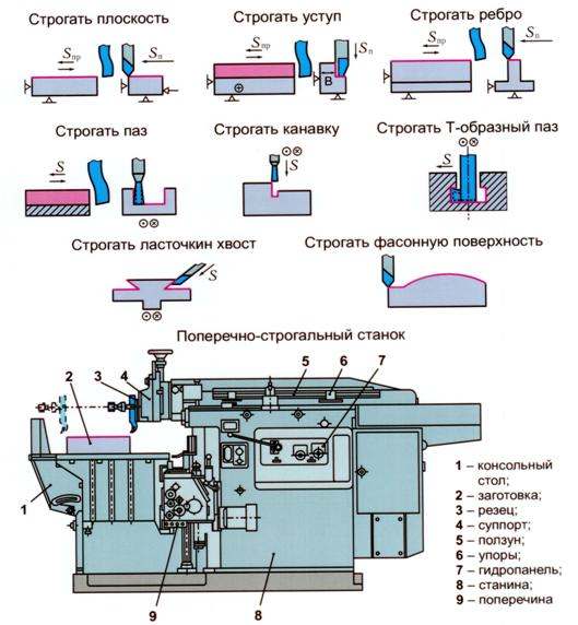
The last two digits of the marking indicate the main technological parameter of the equipment. As a rule, this is the largest dimension of the workpiece in decimeters. For example, brand 7310 will indicate that this unit is cross-planing, and is designed for metal processing with a maximum plane length of up to 1000 mm. The letter in the designation (for example, 7A110) indicates a modification of the basic model (for example, the presence of a hydraulic drive, an additional clamping unit, etc.). The presence of the letter F in the designation indicates that this equipment is equipped with a CNC system.
If you find an error, please highlight a piece of text and click Ctrl+Enter.


How to understand: will the kitten be fluffy?
What kind of light alcohol can be drunk for pregnant women: the consequences of drinking
Why do the legs swell in the ankles and ankles of the feet in pregnant women: causes and methods of treatment
The wedding of Prince Harry and Meghan Markle: scandalous and secret details of the marriage (photo) The future marriage of Prince Harry year NTV
How to close white plums for the winter