In private and industrial construction, preliminary calculations, sketches and drawings are necessary. All recommendations, rules for drawing up drawings and requirements for their design are set out in GOST 21.501-2011, GOST 21.501-93 and many other building regulations, the main provisions of which must be considered if it is necessary to engage in individual or other construction in 2017.
Since the complexity of construction projects, especially industrial and industrial ones, is not specified, all requirements for the implementation of the project must be reflected on paper or in in electronic format as accurately as possible, in compliance with all sizes, drawing rules and other requirements for standardization, which abound modern building. The reality of today is such that it is not always convenient and practical to use electronic gadgets to study drawings directly at the facility under construction. It is much faster to work with paper drawings that can be deployed anywhere without fear of damaging the documentation and without taking additional measures to protect the drawings from damage or damage.
These standards define the content and norms for the design of working documents for structural and architectural tasks that are solved during the construction of buildings and construction objects, as well as the rules and regulations for working documents accompanying products for use in the construction industry.
How to draw up drawings according to GOST 21.501-93
The norms and rules for the design of architectural construction drawings require the use of drawing-linear graphic techniques, which is reflected in working with lines of various thicknesses for clarity and expressiveness of a sketch or drawing. Drawings of elements in a section are highlighted with thicker lines, zones behind the section are drawn with thinner lines. According to GOST in the drawings, you can use lines with limiting values \u200b\u200b(0.2 mm for ink drawing or 0.3 mm for pencil drawing) -1.5 mm. Which lines to use in drawings of different purposes is determined based on its scaling and content. The table below lists the requirements for image scaling in drawings:
- Drawings of plans and facades of the object and drawings of sections of small structures are drawn up on a scale of 1:50;
- Drawings of larger structures are drawn up on a scale of 1:100-1:200;
- Very large industrial facilities are made with scaling from 1:400 to 1:500;
- Elements, parts, structures and individual elements of building objects of any purpose are compiled at a scaling of 1:2-1:25.
The position of all the details of the object is calculated along the coordinate axes. The lines of the horizontal and vertical axes are displayed with a long dash-dotted line, they are marked with a circle image (for example, ①) with the corresponding numbering.
The longitudinal center line in the general plan should be located on the left side of the drawing, the transverse axes - in the lower part of the drawing. If the passage of opposite axes on the sides of the drawing of the construction plan does not match, they are marked on the drawing with continuous numbering on each side.
Important: transverse axles are marked with Arabic numerals from left to right. The longitudinal axes of the section are marked in capital Cyrillic letters (except for the following letters: Y, Z, E, Y, O, X, Y), in the direction from bottom to top
The diameter of the marking circle image adapts to the drawing scale:
- Marking Ø6 millimeters - for drawing scale ≤ 1:400;
- A circle Ø8 millimeters is used in the scale range 1:200-1:100;
- Circle Ø10 millimeters - for drawings on a scale of 1:50;
- The Ø12 mm circle marking applies to 1:25, 1:20 and 1:10 scales.
The main rules for the implementation of architectural and construction working drawings have also been developed in relation to drawing fonts: the character size, which is used to detail the axes, increases by about 2 times relative to the size of the main font of the drawing.
Before sizing, all main lines are marked. Lines for indicating dimensions, located outside the drawing, above which the dimensions of the elements are written, are drawn beyond the outline of the sketch, there can be from 2 to 4 pieces. The first (from left to right) line is supplemented with the sizes of the smallest sections and projections, the second and following lines contain the sizes of larger sections. The last external line must contain the full interaxal dimension with reference to the external walls of the object. Also, the first outer line should start 15-21 mm from the beginning of the drawing. The step between the lines is 6-8 mm, taking into account the placement of size designations between them (in Figure No. 2 - position No. 1).
According to GOST 21.501-93, there are general rules for drawing different sizes of segments on external lines. Segments visually indicating the dimensions of external structures (window, door, partition) are crossed out with extension lines, which are drawn 3-4 mm from the beginning of the drawing to the point of intersection with the external line. At the intersection points, serifs (/ or \) are drawn at a slope of 45 0 . When using a small font size, it is allowed to use dots instead of serifs for sizing. Lines for indicating dimensions from the outside are taken out beyond the extension lines, and are applied along the edges of the plan at a distance of 1-3 mm from the borders.
The dimensions of the premises and other internal structures of the structure are indicated on the internal lines. The step between these lines and the boundaries within the structures and parts of the construction object is chosen arbitrarily, but in such a way that it is convenient to read the drawing. 
The lines for taking out dimensions and their designations in the drawings should be designated as solid thin lines. Numeric graphic representations should be with character sizes ≤ 2.5 mm in ink, and ≤ 3.5 mm in pencil, they should be parallel to the outer line for writing sizes and above it, closer to the center. Dimensional designations are in Cyrillic capital letters and are dimensionally indicated in millimeters.
How are the marks of surface levels and slopes of parts and structures (in Figure No. 3 - position No. 2): dimensional marks visualize the location of individual components. Marks on the plans of objects are applied if there is a difference in heights according to the floor mark. The starting point for the level mark starts from conditional zero - this is the surface of the floor or ceiling of the first floor in a multi-storey building. If it is necessary to mark dimensions below the zero level, all marks are marked with a “-” sign. The “+” sign is not used in the positive level marks. Numerical marks are indicated without designating sizes, they are indicated by meters with an accuracy of three decimal places (X, XXX).

The 45° arrow symbol (\ or /) is used to visualize façade marks, as well as to fix marks on section and section drawings. The arrow should rest against the contour line of the designated part, or the extension line of the structure level for dimensions (window or door opening, niche, partition). Internal marks are written inside the drawing, external marks - outside (in Figure No. 3 - position No. 1).
On the plan, the take-out lines of dimensions should be solid thin. Numerical designations of sizes should have a character size ≤ 2.5 mm in ink, and ≤ 3.5 mm in pencil, drawn parallel to the outer extension line and above it, closer to the center. Dimensions are written in millimeters in Cyrillic characters. 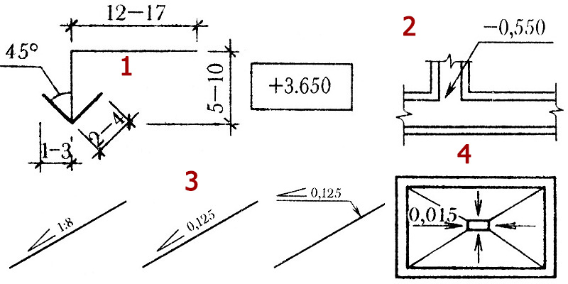
On the plans of structures, marks are placed in a rectangle or on a drawn shelf of an extension line. In this case, the level sign must be indicated: “-” or “+”. The difference is one thing - for structural drawings, the marks are indicated on the extension lines, and on the architectural drawings, the marks are placed in a rectangle (in Figure No. 3 - position No. 2).
The degree of inclination in section indications is written as a simple or decimal fraction with an accuracy of three decimal places. The symbol for tilt is written like this: Ð. This symbol is written above the contour line or on the extension line-shelf (in Figure No. 3 - positions No. 3 and No. 4). In the drawings of plans for buildings and structures, the surface slope vector is indicated by the symbol Р, next to which the angle of inclination is written in degrees.
How to indicate the place of a cut or section of a part: this is an open solid line with a removal to the drawing. It denotes the continuation of the start and end points of the cutting plane. If it is necessary to indicate a broken section of a complex configuration, then the drawing should show excerpts from the overlap of the cutting planes.
The direction in which the drawing should be viewed is indicated in 2-3 millimeters from the end of the open line in the form of an arrow ® or →. All zones of dissections and incisions are indicated by Cyrillic letters and numbers, located under the arrow of the direction of view (for a cut across the part), and to the side outside the arrow - for a cut along the part or longitudinal assembly (positions No. 1 and No. 2 in Figure No. 4). 
How the area of the object and the interior is indicated in the drawings: the area values \u200b\u200bare indicated in m 2, two characters are written after the integer, the dimension of the area is not additionally indicated, the numbers are underlined below. The place for designating the area for each room in the drawing is in the lower right corner. Additionally, the total and useful area of \u200b\u200bhousing is indicated - this is done in the form of a simple fraction with a living area in the numerator, and with a useful one - in the denominator of the fraction. Before designating the area, the number of all rooms in the house or apartment is indicated in numbers without underlining.
If the design requires the designation of individual parts, then explanatory inscriptions are placed on a broken line-shelf, which, with its slope, is directed towards the part. On the horizontal line of the shelf, the dimensions of the part are prescribed. If the drawing is small, then it is allowed to draw an extension line without ending with an arrow. The inscriptions that are placed on special lines, and indicating the dimensions of multicomponent structures, are made in the form of "flags". The inscriptions are arranged one after another, in the same order in which the structural layers and components of the structure are visible from left to right and from top to bottom. The thickness of each layer is indicated in millimeters without a letter indicating the dimension.
Marking of structural elements to indicate their location is indicated by extension broken lines. It is allowed to combine several shelves into one or indicate the marking of the part without taking out dimensions directly next to the image of the part. The marking font should be larger than the general font of the drawing (position No. 1 in Figure No. 5).
Numbering and deciphering the dimensions of structural fragments is an important part of the design of the sketch, and helps to quickly understand the drawing. Marking aims to combine individual enlarged fragments of the drawing and more detailed painted sections of the main drawing. 
When making a visual callout of the details of the object, the corresponding section is indicated by a solid closed line in the form of an oval or circle, indicating ordinal numerical or alphabetic characters on the extension shelf. If it is impossible to place a separate node on the same drawing with the main sketch, it is taken out on a separate sheet, and the serial number of the drawing sheet is written under the shelf of the extension line (position No. 2 in Figure No. 5). On the side or above the removed part, regardless of sheet numbering, a double circle Ø 10-14 millimeters is drawn, in which the serial number of the removed part is written.
Construction drawings technical purpose should have explanatory captions for images, text explanations, tables and other explanatory elements. For explanatory footnotes, a direct standard font is used according to GOST type A (GOST type A) and GOST TYPE B (GOST type A) with a character height of 2.5-14 millimeters. Fonts ranging in size from 5 to 10 millimeters are used for writing the titles of drawing graphics, fonts of 2.5-3.5 millimeters are used for writing text, and sizes of 10 and 14 millimeters are used to accompany illustrations to drawings. Headings for images must be placed above them, and underline them, like the headings of accompanying texts, with a solid lowercase line. Only the headings of tables and specifications are not underlined.
Detailing the floor plan of the house and the explication of the premises
Drawing terminology provides for an indication in the headings of plans to indicate the zero level of the floor (or the serial number of the floor). Example: "Floor plan at X, XXX", or "X-XX floor plan". GOST is allowed to designate the functional purpose of objects on the floor in the title of the plan. This may be "Layout of the technical room", "Basement plan".
The floor plan is a horizontal section at the level of the window, 5-10 centimeters above the upper border of the window sill, or a section of the floor at a height of one third from the bottom. If the windows on the floor are located in several tiers, then the plan is drawn up within the boundaries of the lower windows of the floor. All details passing along the section in the plan are highlighted with a thick solid line.
The floor plan should include the following elements:
- Object coordinate axes, denoted by a thin dash-dotted line;
- Consistent indication of the dimensions of structures plus the width between the axes, the width of partitions and walls, the dimensions of doors and windows;
- The level of the finished floor, if the floor on the floor has several levels;
- Indication of sections with the presence of windows and doors in them;
- Door and window markers, marking of internal wall lintels with a circle ⃝ 5 mm, thin line execution;
- Names of detailing and layout sections;
- Names and sizes of the area of all rooms on the floor.
The standards allow the headings of the names of the premises and the amount of area to be indicated in the explication in the appropriate form. That is, not titles or names are indicated, but a detailed numbering of objects is done. For individual drawings of internal areas and objects, visualization is carried out by drawing a thin solid line indicating the main load-bearing elements. Everything that is above the cut line is shown as a thin dash-dotted line with two dots, without detail. 
Figure 6 shows detailed plan one floor of a building made of foam blocks. What includes detailing using different building materials:
- Aerated concrete walls ( standard sizes foam block - 390 x 190 x 190 mm);
- The thickness of all walls must be (according to the plan) a multiple of 100 mm;
- Minimum internal thickness foam concrete walls 200 mm;
- Maximum outer thickness brick walls at home - 600 mm plus 100 mm for the heat-insulating layer;
External walls for a brick house:
- Thickness outer wall must be a multiple of 130 mm, up to and including 640 mm;
- Dimensions ceramic bricks- standard, 250 x 120 x 65 (or 88) mm.

For a log house:
- Thickness external walls at home - 150-220 mm;
- The minimum thickness of the internal walls of the house is 180 mm.
- The maximum thickness of the outer walls is 220 mm.
For a log house:
- The thickness of the external load-bearing walls should be a multiple of 20 mm, and range from 180 to 320 mm;
- The minimum thickness of internal load-bearing walls is 180 mm;
- The maximum thickness of external walls is 180-320 mm;
- The interior walls are wooden frame with insulation (in Figure No. 7 - positions Nos. 1-5);
- Frame thickness - up to 180 mm;
- The minimum thickness of internal load-bearing walls is 100 mm;
- The maximum thickness of the outer walls is 150 mm.
Partitions internal:
- Cellular concrete 190 mm thick;
- Brick 120 mm thick;
- Wooden frame 75 mm thick;
- Drywall with partition thickness up to 70 mm.
Windows and entrance doors:
- In the wall of cellular concrete;
- In a brick wall;
- AT wooden walls from various lumber.
The axis coordination system in is intended for the correct distribution of area and volume in the building, the optimal distribution of areas, and as a basis for calculating the dimensions of parts. Based on this task, all elements of the object are tied to axial coordinates.
Coordination axes in the drawing of a building object are lines along the central axes in different directions, parallel to which all internal structures structures. The span in the drawing is the distance between the axes in one placement vector of the main structure of the object. The distance between the axes in another (any) vector is a step. Steps and spans are determined by the dimensions of building beams, slabs, columns or crossbars.
GOST 21.101-97
INTERSTATE STANDARD
SYSTEM OF DESIGN DOCUMENTS FOR CONSTRUCTION
MAIN REQUIREMENTS FOR PROJECT AND WORKING DOCUMENTATION
5. GENERAL RULES FOR DOCUMENTATION
Coordination axes
5.4. Coordination axes are indicated on the image of each building or structure and an independent notation system is assigned to them.
Coordination axes are applied to the images of the building, structures with thin dash-dotted lines with long strokes, denoted by Arabic numerals and capital letters of the Russian alphabet (with the exception of the letters: Ё, 3, Ъ, O, X, C, Ch, Щ, b, Y, b) in circles with a diameter of 6-12 mm.
Omissions in numerical and alphabetic (except for those indicated) designations of the coordination axes are not allowed.
5.5.
The numbers indicate the coordination axes along the side of the building and structures with a large number of axes. If there are not enough letters of the alphabet to designate the coordination axes, subsequent axes are designated by two letters.
Example: AA; BB; VV.
5.6. The sequence of numerical and alphabetic designations of the coordination axes is taken according to the plan from left to right and from bottom to top (Fig. 1a) or as shown in Fig. 1b, c.
5.7.
The designation of the coordination axes, as a rule, is applied on the left and lower sides of the plan of the building and structure.
If the coordination axes of the opposite sides of the plan do not coincide, the designations of these axes at the divergence points are additionally applied on the upper and / or right sides.
5.8.
For individual elements located between the coordination axes of the main supporting structures, additional axes are applied and denoted as a fraction:
above the line indicate the designation of the previous coordination axis;
under the line - additional serial number within the area between adjacent coordination axes in accordance with fig. 1g
It is allowed to assign numerical and alphabetic designations to the coordinating axes of half-timbered columns in continuation of the designations of the axes of the main columns without an additional number.
5.9. On the image of a repeating element attached to several coordination axes, the coordination axes are designated in accordance with Fig. 2:
"a" - with the number of coordination axes not more than 3;
"b" - with more than 3 coordination axes;
"c" - for all alphabetic and digital coordination axes.
If necessary, the orientation of the coordination axis, to which the element is attached, in relation to the neighboring axis, is indicated in accordance with Fig. 2y.

Rice. 2
5.10.
To designate the coordination axes of block sections of residential buildings, the index "c" is used.
Examples: 1s, 2s, Ac, Bs.
On the plans of residential buildings, arranged from block sections, the designations of the extreme coordination axes of the block sections are indicated without an index in accordance with Fig. 3.

Rice. 3
Dimensions on construction drawings are applied in accordance with GOST 2.307-68 *, taking into account the requirements of GOST 21.101-97.
The basis for determining the size of the depicted product and its elements are the dimensional numbers printed on the drawings.
Let us dwell on the main features of applying dimensions on construction drawings:
1. The dimension line at its intersection with extension, contour or center lines is limited not by arrows, but by serifs in the form of segments of the main lines 2-4 mm long, drawn at an angle of 45 (tilt to the right) to the dimension line (Fig. 46).
Figure 46 - Inscription:
a) - serifs on dimension lines; b) – gaze direction arrow
2. Not only the extension lines should protrude beyond the dimension lines by 1-5mm, but the dimension lines should also protrude beyond the extreme extension lines by 1-3mm (Fig. 47).
3. It is allowed to intersect the dimension line with an extension line and other dimension lines.
4. On construction drawings, it is allowed to repeat the dimensions of the same element, as well as to apply dimensions in the form of a closed chain. Recall here that the distance from the outer contour of the image to the first dimension line must be at least 10 mm, and between parallel dimension lines at least 7 mm (Fig. 47). When placing various building elements outside the plan dimensions, the distance from the first dimension line to the plan outline can be increased to 20 mm or more.

Figure 47 - Dimensioning in construction drawings
On facades, sections and sections, elevation marks of levels (heights, depths) of a building or structure element are applied from any calculated level, taken as "zero". Marks are placed on extension lines or contour lines and are marked with a sign, which is an arrow with a shelf. The arrow is shown as right angle, resting with its top on the extension line and having sides drawn by the main lines (0.7-0.8mm) at an angle of 45 ° to the extension line or contour line (Fig. 48). The vertical segment, shelf and extension line are made with a thin solid line (0.2-0.3 mm). The marks characterizing the height of the levels are indicated in meters with three decimal places after the decimal point. The plane, from which the subsequent levels start, is called the zero level and denotes the mark without a sign - "0.000". The marks above the zero level, which is taken as the clean floor of the first floor, are indicated with a plus sign (for example, +2.500), and the levels below are indicated with a minus sign (for example, - 0.800). If near one of the images there are several level marks located one above the other, then it is recommended to place the vertical lines of marks with arrows on the same vertical, and make the shelves the same length. On the images, the level marks are put down, if possible, in one column. Marks may be accompanied by explanatory inscriptions, for example: Ur.ch.p.- clean floor level, Ur.z.- ground level (Fig. 48). On the drawings of plans, it is allowed to apply elevation marks of buildings in rectangular or on the shelf of leader lines.

Figure 48 - Drawing level marks on facades, sections, sections:
a) - dimensions of the level mark;
b) - examples of the location and design of signs on the images;
c) - examples of level signs with explanatory inscriptions.
4. On construction drawings, it often becomes necessary to put down the magnitude of the slope (the tangent of the angle of inclination - the ratio of the excess to the foundation). The slope itself in the drawings (except for plans) is indicated by the conventional sign "Р", the acute angle of which should be directed towards the slope and which is applied directly above the contour line or on the shelf of the leader line (Fig. 49). The slope value is indicated by a dimensional number in the form of a simple fraction or decimal up to the third decimal place. In some cases, the designation of the slope of the element (rod) is used right triangle with vertical and horizontal legs, the hypotenuse of which coincides with the axis or the outer contour line of the depicted element. Above the legs put down the absolute or relative value of their values, for example, 50 and 125.

Figure 49 - Examples of drawing on the drawing the magnitude of the slope
According to the standards in force in our country, all dimensions on technical drawings must be placed in strict accordance with certain rules, requirements and norms. In accordance with them, all those dimensional numbers that are located above the dimension lines should be applied closer to their middle parts. In cases where there are several concentric or parallel dimension lines in the drawing, the dimension numbers must be applied in a checkerboard pattern.
The standards also state that when applied to blueprints remote and dimension lines intersections should be avoided. Those arrows that limit the dimension lines must be depicted in such a way that with their tip they rest against the contour, axial or extension lines.
Extension lines should extend beyond the ends of the arrowheads to a distance of 1 to 5 millimeters. As for such a parameter as the minimum distance that should be between dimension lines located parallel to each other, it is equal to 7 millimeters. Minimum distance between contour line and dimension line should be 10 millimeters. The specific values of these parameters in each individual case are selected depending on the saturation of the drawing and the size of the image.
Location of dimensions on the drawing
If all dimensions to be specified on the drawing, refer to the same structural element of the displayed part (hole, protrusion, groove, etc.), then it is best to place them in the place where it is visually depicted most fully, and grouping all the necessary values.

Dimensioning structural element
Allowed dimensioning directly on dimension lines that have some slope relative to the horizontal or vertical. In cases where it becomes necessary to apply one or another dimension in the area that is shaded, it should be placed on the leader shelf.

Location of dimension numbers at different slopes

An example of applying a linear dimension
As for elements such as limit deviations and dimensional numbers, according to current standards, they cannot be separated or crossed by any lines on the drawings. In addition, it is unacceptable to break the contour line in order to apply a dimension number. You can also not place it in those places where center, center or dimension lines intersect.

Dimensioning a hatch

Dimensioning example
If there is such a need, then it is allowed to apply dimensions with an offset. In such cases, extension and dimension lines form a parallelogram along with the segment that is being measured.
Dimensions on the drawings are applied in accordance with GOST 2.307 - 68 *
taking into account the requirements of GOST 21.501 - 93 for construction drawings.
Dimensional numbers printed on the drawing serve as the basis for determining the size of the depicted product (structural element, assembly, building, structure). The drawing should contain a minimum number of dimensions, but sufficient for the manufacture of a product or structural element, as well as for the production of work.
The dimensions in the drawing are indicated by dimensional numbers and dimension lines. Dimensions are given in millimeters, without indicating the unit of measure. If the dimensions are indicated in other units of measurement, then the corresponding dimensional numbers are recorded with the designation of the unit of measurement (cm, m, etc.) or indicated in technical requirements. The dimension number should always indicate the actual size of the part (structure), regardless of the scale of the drawing.
Dimension lines should preferably be applied outside the outline of the image, and should not be separated or crossed by any lines of the drawing.
Dimensional and extension lines are drawn with solid thin lines. To limit the dimension lines at their intersections with contour lines, extension, axial, center and others, apply: serifs - in the form of a short stroke drawn by the main line with an inclination to the right at an angle of 45˚ to the dimension line; in the form of an arrow - for sizes of diameters, radii, angles; in the form of a point - with a lack of space for serifs on dimension lines located in a chain. The distance of the dimension line from the contour line parallel to it, axial, extension and other lines, as well as the distance between parallel dimension lines must be at least 7 mm, and from the dimension line to the circle of the coordination axis - 4 mm. For general view drawings (plans, sections, facades, etc.), dimension lines are located, depending on the size of the images, at a distance of at least 10 mm (14 ... 21 mm is allowed) from the outer contour line. On fig. 3 shows examples of drawing dimension and extension lines in the drawings.
Fig.3. Drawing dimension and extension lines
Conditional level marks (heights, depths) on plans, sections, facades show the distance in height from the surface level of any building structural element located near the planning surface of the earth. This level, as a rule, the level of the “clean” floor of the first floor is taken as zero. On facades and sections, marks are placed on extension lines or contour lines. The leader line, horizontal and vertical, is drawn with a solid thin line. The mark sign is an arrow with a shelf (Fig. 4). The mark mark may be accompanied by explanatory inscriptions, for example: “Lv. h.p.” - the level of the clean floor; "Ur. h.” - ground level.
On construction drawings, level marks are indicated in meters with three decimal places separated from the whole number by a comma. The conditional zero mark is designated - 0.000. A dimensional number showing the level of an element located below the zero mark has a minus sign (for example, - 1.200), and located above - a plus sign (for example, + 2.750).
On the plans, the dimensional number of the mark is applied in a rectangle, the contour of which is circled by a thin solid line, or on the shelf of the leader line, with the obligatory insertion of a plus or minus sign (Fig. 5).
Rice. 4. Drawing height marks on the drawings of facades,
cuts and sections
Rice. 5. Drawing level marks on the building plan:
a - in a rectangle; b - on the shelf-leader
Depending on the accepted method of representation and the nature of the dimensions on construction drawings, some dimensions (for example: slopes, lengths of structural elements, dimensions of rolled profiles, etc.) are applied without dimension and extension lines. The magnitude of the slope (the tangent of the angle of inclination, i.e., the ratio of the excess to the laying) is indicated by a dimensional number in the form of a simple fraction. It is allowed, if necessary, to indicate the value of the slope as a decimal fraction with an accuracy of up to the third decimal place.
The tool for constructing elevation marks (levels) on sections/facades (button
located in the settings window linear dimensions. When this tool is activated, the window for setting parameters of linear dimensions changes (Fig. 8.13).
Rice. 8.13. Elevation settings mode
In the list of standard levels, in addition to the zero level of the project and two user-defined base levels, you can select an elevation relative to the user coordinate system. This option is available if the origin of the standard coordinate system is changed by the user.
Elements designed to control the type of marker (Fig. 8.14) are arranged in two rows.

Rice. 8.14. Elevation Marker View Controls
Using the buttons of the first row, the general view of the marker is selected. The selected option is specified using three switches located in the second row. The first switch determines whether the marker icon should be positioned relative to the elevation line - top or bottom. The second switch specifies the shape of the marker icon. The third switch determines whether the icon is filled.
When you select a marker image in the form of a level mark icon on the floor plan - a circle divided into four sectors, the lower row of controls changes (Fig. 8.15).

Rice. 8.15. Elevation Marker View Options on the Floor Plan
The first switch determines the position of the dimension text relative to the marker icon, the second - the shading option.
The switch that determines the presence of a sign in front of the level value can be set to two positions. When set to the first position, the + (plus) sign is not displayed at a positive elevation, when set to the second, this sign is displayed. With negative elevation, the - (minus) sign is set regardless of the position of this switch.
Activating the tool for constructing elevation marks also changes the appearance of the information palette (Fig. 8.16).
Rice. 8.16. Information palette when activating the elevation tool
On the information palette, the above elements for setting the parameters of elevation marks become available.
Dimensions on construction drawings are applied in accordance with GOST 2.307-68 *, taking into account the requirements of GOST 21.101-97.
The basis for determining the size of the depicted product and its elements are the dimensional numbers printed on the drawings.
Let us dwell on the main features of applying dimensions on construction drawings:
1. The dimension line at its intersection with extension, contour or center lines is limited not by arrows, but by serifs in the form of segments of the main lines 2-4 mm long, drawn at an angle of 45 (tilt to the right) to the dimension line (Fig. 46).
Figure 46 - Inscription:
a) - serifs on dimension lines; b) – gaze direction arrow
2. Not only the extension lines should protrude beyond the dimension lines by 1-5mm, but the dimension lines should also protrude beyond the extreme extension lines by 1-3mm (Fig. 47).
3. It is allowed to intersect the dimension line with an extension line and other dimension lines.
4. On construction drawings, it is allowed to repeat the dimensions of the same element, as well as to apply dimensions in the form of a closed chain. Recall here that the distance from the outer contour of the image to the first dimension line must be at least 10 mm, and between parallel dimension lines at least 7 mm (Fig. 47). When placing various building elements outside the plan dimensions, the distance from the first dimension line to the plan outline can be increased to 20 mm or more.

Figure 47 - Dimensioning in construction drawings
On facades, sections and sections, elevation marks of levels (heights, depths) of a building or structure element are applied from any calculated level, taken as "zero". Marks are placed on extension lines or contour lines and are marked with a sign, which is an arrow with a shelf. The arrow is depicted as a right angle, resting with its top on the extension line and having sides drawn by the main lines (0.7-0.8 mm) at an angle of 45 ° to the extension line or contour line (Fig. 48). The vertical segment, shelf and extension line are made with a thin solid line (0.2-0.3 mm). The marks characterizing the height of the levels are indicated in meters with three decimal places after the decimal point. The plane, from which the subsequent levels start, is called the zero level and denotes the mark without a sign - "0.000". The marks above the zero level, which is taken as the clean floor of the first floor, are indicated with a plus sign (for example, +2.500), and the levels below are indicated with a minus sign (for example, - 0.800). If near one of the images there are several level marks located one above the other, then it is recommended to place the vertical lines of marks with arrows on the same vertical, and make the shelves the same length. On the images, the level marks are put down, if possible, in one column. Marks may be accompanied by explanatory inscriptions, for example: Ur.ch.p.- clean floor level, Ur.z.- ground level (Fig. 48). On the drawings of plans, it is allowed to apply elevation marks of buildings in rectangular or on the shelf of leader lines.

Figure 48 - Drawing level marks on facades, sections, sections:
a) - dimensions of the level mark;
b) - examples of the location and design of signs on the images;
c) - examples of level signs with explanatory inscriptions.
4. On construction drawings, it often becomes necessary to put down the magnitude of the slope (the tangent of the angle of inclination - the ratio of the excess to the foundation). The slope itself in the drawings (except for plans) is indicated by the conventional sign "Р", the acute angle of which should be directed towards the slope and which is applied directly above the contour line or on the shelf of the leader line (Fig. 49). The slope value is indicated by a dimensional number in the form of a simple fraction or a decimal fraction with an accuracy of up to the third decimal place. In some cases, the designation of the element (rod) slope is used as a right-angled triangle with vertical and horizontal legs, the hypotenuse of which coincides with the axis or the outer contour line of the depicted element. Above the legs put down the absolute or relative value of their values, for example, 50 and 125.

Figure 49 - Examples of drawing on the drawing the magnitude of the slope
Stroke rules for drawings. Inscriptions. Scales. Dimension. Marks for binding elements of buildings and structures in height. Product marking
The rules for the graphic design of drawings are similar to the rules for the execution of engineering drawings, taking into account some features in choosing scales, applying dimensions, sequencing drawings, etc. Stroke of construction drawings is carried out in accordance with GOST 21.501-93. The thickness of the lines when tracing the drawings of plans, sections and facades is taken depending on the accepted scale. So, for example, at a scale of 1:100, the thickness of the contour lines when tracing plans and sections of buildings and structures made of stone and reinforced concrete is taken equal to 0.6-0.7 mm, and facades, window and doorways- 0.4-0.5 mm; at a scale of 1:400, the thickness of the contour lines is taken to be 0.4 mm and 0.3 - 0.4 mm, respectively. The thickness of the contour lines when tracing the details of stone, brick and concrete elements at a scale of 1:20 is taken equal to 0.8 mm, and at a scale of 1:1 - 1 mm. On the plans of architectural and construction drawings, floors are highlighted with thicker lines, and the contours of the walls are outlined with lines somewhat thinner. In the drawings of building structures, reinforcement is also distinguished by thick lines, and the contours of the structure itself are thinner, etc.
Inscriptions on construction drawings are made in font according to GOST 2.304-81. The font size for different inscriptions is applied differently. In the main inscription: the name of the design organization, object, sheet, etc. performed with a height of 5-7 mm, other inscriptions - with a height of 3.5-5 mm; the name of the main drawings and tables is 5-7 mm high, and the secondary drawings and text instructions are 3.5-5 mm high; digital data for filling tables -2.5-3.5 mm. The designation of the coordinating axes, reference and numbering of nodes, position numbers with a circle diameter of up to 9 mm is performed in a font size of 3.5 or 5 mm high, and with a diameter of more than 10 mm - 5 or 7 mm.
The height of dimensional numbers in drawings made on a scale of 1:100 and larger is taken equal to 3.5 mm, and for scales of 1:200 and less - 2.5 mm.
Scales on construction drawings according to GOST 21.101-79 are not marked. However, if necessary, it is allowed to indicate the scale in the main inscription according to the type 1:10, 1:100, etc., and above the image according to the type “А-А (1:50)”. scale of images of plans, facades, sections, structures, etc. should be taken as minimal, taking into account the complexity of the image, but it is necessary to ensure the clarity of the image, taking into account modern methods of reproduction of drawings. The scale of images of plans, sections, facades, structures, etc. civil, industrial, agricultural, transport buildings and structures are performed in accordance with GOST 2.302-69, taking into account the requirements of GOST 21.501-93. So, for example, floor plans (except for technical ones), sections, facades, plans, ceilings, coatings, wiring diagrams of frames are drawn at a scale of 1:400, 1:200, 1:100, and with greater saturation of images - 1:50; roofing plans, floors, technical floors - on a scale of 1:1000, 1:800, 1:500, 1:200; fragments of plans, facades, plans and sections of stairs, installation diagrams of internal walls - on a scale of 1:100, 1:50; foundation plans - on a scale of 1:200, 1:100; nodes - on a scale of 1:20, 1:10, 1:5, etc.
Dimensions on construction drawings are applied in accordance with GOST 2.303-68, taking into account the requirements of the design documentation system for construction - GOST 21.105-79. Dimensions in mm on construction drawings are applied in the form of a closed chain without indicating the unit of measurement. If dimensions are given in other units, such as cm, then they are specified in the notes to the drawings. Dimension lines are limited by serifs 2–4 mm long at an angle of 45 ° to the dimension line with an inclination to the right. The thickness of the serif line is taken equal to the thickness of the solid main line adopted in this drawing. Dimension lines should protrude 1 - 3 mm beyond the extreme extension lines. The dimension number is located above the dimension line at a distance of up to 1 mm. The distance from the drawing outline to the first dimension line is assumed to be at least 10 mm. The distance between parallel dimension lines must be at least 7 mm, and from the dimension line to the circle of the coordination axis - 4 mm (Figures 10.5-10.8).
Figure 10.5 - Coordination axes: a - no more than 3; b - more than 3; c - with alphabetic and digital axes; d - with the orientation of the coordination axes
Marks for binding elements of buildings and structures in height are indicated in meters with three decimal places after the occupied one. For conditional zero mark the mark of the finished floor of the first floor, denoted by 0.000, is accepted. Marks above the conditional zero are indicated without a sign, and below the conditional zero - with a minus sign (-). On facades and sections, marks are placed on extension lines or contour lines. Mark mark is an arrow with a shelf. The arrow is made with main lines 2–4 mm long, drawn at an angle of 45 ° to the extension line or contour line. The mark mark may be accompanied by explanatory inscriptions. For example: Ur. n.p. - the level of the clean floor, Ur. h. – ground level (Figure 10.6).

Figure 10.6 - Applying elevation marks on the drawings of facades, sections, sections: a - conventional mark mark; b - location of mark mark and shelf; c - application of the mark; g - the same, with explanatory signs

Figure 10.7 - Restriction of dimension lines: a - serif; b - arrow, (s - thickness of the main line); in - dot

Figure 10.8 - Drawing dimension and extension lines
Typical products are marked stamps in accordance with the drawings of typical products, catalogs and standards.
The brand of products on construction drawings is applied next to the products or on the shelves of extension lines. For example, for prefabricated panel buildings, the panel inner wall may be designated B24, and external H14, etc. (Figure 10.9).

Figure 10.9 - An example of marking products (window and door openings) in the drawing
The design and construction of buildings and structures is carried out in strict accordance with building codes and rules (SNiP), "Unified System for Design Documentation" (ESKD), which are collections of state standards (GOST), "Project Documentation System for Construction" (SPDS), instructions for the composition and execution of drawings, the use of which is mandatory for all design and construction organizations.


Why dream of stealing a car and is it worth being afraid of a repetition of this in reality?
What is transmitted genetically to the child from the mother and what is the father From whom the genes are transmitted to the child
How to get rid of snails in the garden forever with folk remedies?
Lavender tea drinking: benefits and recipes of lavender tea
Economic strategies review and description House building games