Numerical control (abbr. CNC; English computer numerical control, abbr. CNC) is a computerized control system that controls drives technological equipment including machine tools.
Having decided on the bed, I sat down at the drawings of the machine, initially made them in SPlan7, and why not, the program is universal. It is convenient when there is a drawing with dimensions one to one. I drew a frame, a top view and a side view, drew bearings on the sides, I could immediately determine the size of the Z-axis drive screw. Of course, I couldn’t draw everything at once, because, as there weren’t all the installation nodes available - guide shaft supports, linear bearings, drive couplings, guide shafts of axes, stepper motors, spindle mounts, bearing supports.
It's time for orders stepper motors- Nema23 (23HS6403), ordered with www.duxe.ru, spindle mount (diameter 52mm) and drive sleeves (6.3mm / 8mm) - http://www.aliexpress.com, axle guide shafts, linear bearings in the housing, guide shaft supports, bearing supports were also sharpened according to my drawings on - www.cnc.gollos.com.ua .
As I received the ordered components, I drew them in three views and then used them for drawing in the drawings as elements of the library, very convenient. Gradually, not quickly, the machine was completely built in three projections and now you can shoot any size of interest.
Having decided on running meters and the dimensions of the profile pipes, ran to the metal warehouse. I bought a not easy pack of profile pipes, pulled them home, since they are nearby.
Now we are moving from theory, drawing and purchases, to practice. We need a large list of tools, fixtures and services:
Power tool.
1. Angle grinder, small (500-700W);
2. Electric drill, with speed control;
3. Welding machine, preferably semi-automatic;
Measuring tool, marking.
1. Roulette (2m.);
2. Metal ruler (0.5m.);
3. Square (from 200mm.);
4. Scriber for metal (with winning soldering);
Metal cutting and processing tools.
1. Cutting discs for metal (diameter 125mm, thickness 1.6mm)
2. Cleaning circles (petal);
3. Nozzles abrasive, for a drill (cylindrical, 15-20mm.);
4. Sanding paper (medium and fine);
5. Files for metal (square, flat, circle and semicircle);
6. Crown for metal, with victorious soldering (diameter 18mm.);
7. Carbide drills, HSS (diameter - 3.5mm., 5.5mm., 10mm.);
Clamping tool and fixtures.
1. Hex keys (4mm.);
2. Open-end wrenches or adjustable (8mm., 22-24mm.);
3. The vise is large;
4. A set of clamps for metal of different sizes (plus home-made ones);
Services.
1. Turning works;
2. Welding work;
3. Laser or plasma cutting of sheet metal;
4. Online stores;
5. Base of metal-roll (profile and sheet metal);
It is also necessary to have “direct hands”, preferably four, a lot of free time and patience.
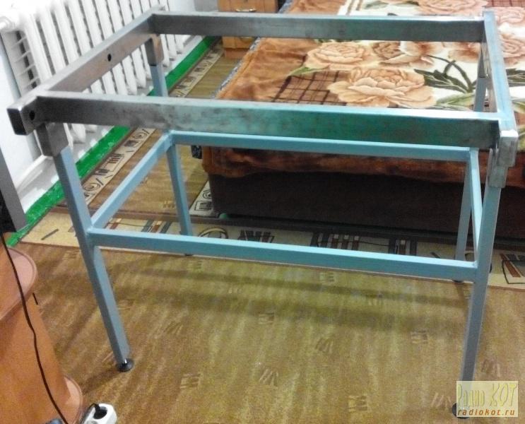
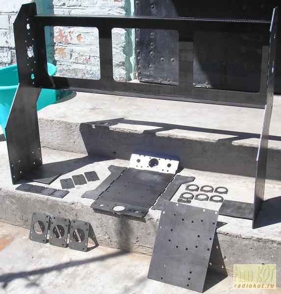
So, let's start with the bed of the Z axis of the machine.
For the frame we use a profile pipe with a section of 30x60x2mm. We need segments: 903mm. - 2 pcs. (longitudinal sections of the bed), 718mm. - 2 pcs. (transverse segments of the bed), 80mm. - 4 things. (bed legs). The bed will turn out to be universal, it can be installed on a table or put on a base.
To get pipe segments of the required length, follow the sequence:
1. We take a pipe with a margin in length, on the one hand we make a circular marking for a square;
2. Next, we clamp it in a vice, using an angle grinder, we end the pipe along the marking line, making cuts from each of the four sides of the pipe, and not in one cut;
3. After trimming, we remove the scale inside and outside the pipe with a square and flat file;
4. Check the end of the pipe with a square, on each side, adjust if necessary;
5. After trimming the base edge, using a tape measure, mark the required length and repeat steps 2-4.
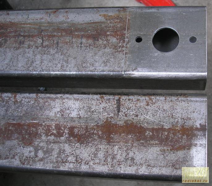
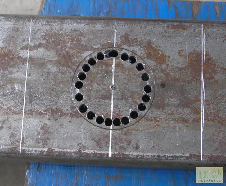
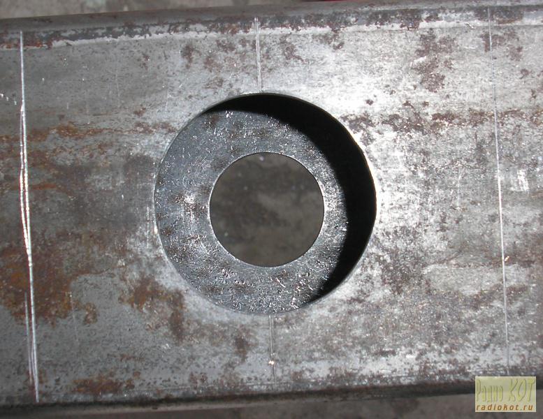
After the performed operations, we proceed to marking the holes on the transverse sections of the frame for the installation of guide shaft supports, bearing supports of the drive screw, mounting pinch screws (18mm crown), studs for installing stepper motors. Marked, drilled, now you can carefully clean the surface of the pipes.
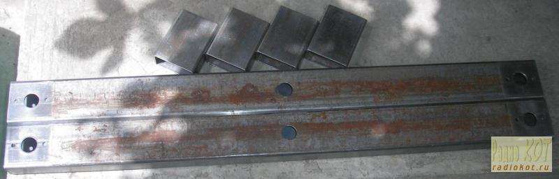
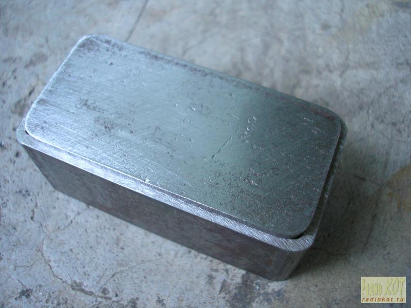
For the ends of the transverse pipes, we will make plugs from pieces of pipes.
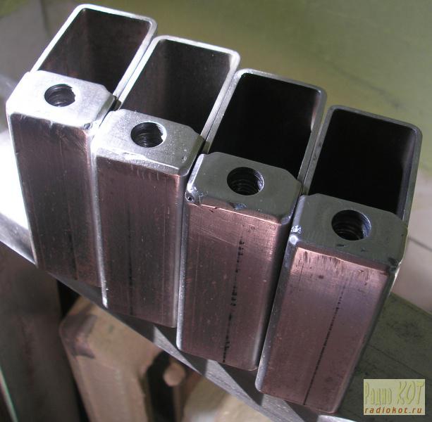
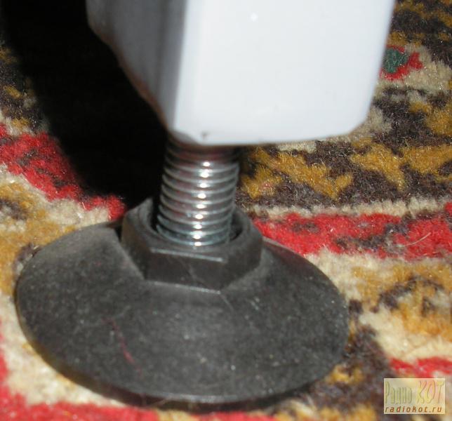
Plates with threads will be welded into the legs of the bed, into which we will screw the adjustable supports.
The same adjustable feet can be rearranged into the base of the machine.
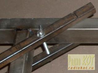
To weld the frame, it is necessary to assemble it on the M16x1000 mounting studs and tighten it at the corners with home-made profile clamps. Clamps are two sections of a profile pipe, 20x30x250mm in size, with 8.5mm holes. in the centers, tied together with studs 150 mm long. and diameter 8mm (M8).
Assembly should be carried out on a square, with measurements of the diagonals of the bed, then tighten all the coupling nuts and once again check the right angles and diagonals.
To transport the bed in this form, I wrapped it with a vacuum cling film, because the cleaned and polished metal shows rust stains very well, not only from wet weather, but also from wet and greasy hands.
Welding of the frame is carried out in stages:
1. We dismantle the vacuum food film;
2. Check if the angles and dimensions of the diagonals are not lost;
3. We install the frame in a horizontal position, either on the floor or on the welding table;
4. First, we make tacks, dots, cross to cross with bed overturns, let cool;
5. Now, according to the same scheme, we make continuous penetrations, let it cool;
6. With petal, cleaning wheels, we clean the welding seams and see if there are any penetration gaps, if there are, we eliminate them;
7. After cooling, you can remove the clamps from the corners;
8. We pre-weld nuts on the plates from adjustable supports (it can be elongated) and weld them to the legs, clean them, let them cool;
9. We mark the mounting locations of the legs on the bed and fix them on clamps for metal;
10. We grab, boil and clean, let cool;
11. We remove the tie rods and weld the holes from them, since they were auxiliary.
The bed is ready.
The filling of the frame, the “Z” axis, consists of:
1. WCS linear guide shafts, diameter 16mm, length 1000mm, quantity 2pcs;
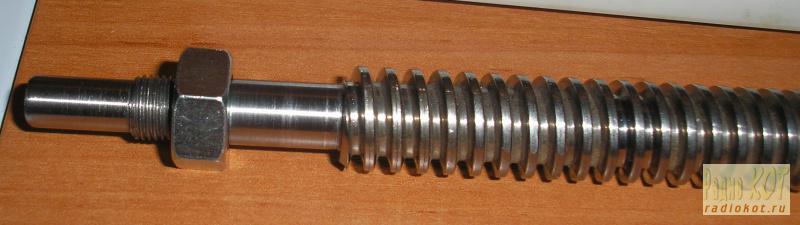
5. Trapezium screw with cutting ends, length 1000mm and caprolon nut;
All fasteners M5, only different lengths.
We continue, the portal is the "Y" axis and the "Z" axis.
The portal and the axis will be made of sheet metal measuring 1000x1000x3mm, using laser cutting, namely laser cutting, because plasma cannot cope with the smallest details. To make parts from sheet metal, you need to draw them in CorelDRAW or AutoCAD, observing a number of requirements:
Technical requirements for drawings for plasma cutting:
1. File formats: AutoCAD, SolidWorks, Kompas (preferably *.dxf);
2. All characters and text must be converted to curves;
3. The distance between the parts is greater than or equal to the thickness of the metal, but not less than 6mm;
4. The distance from the edge of the sheet to the details is equal to the thickness of the metal, but not less than 10mm.
I had to redraw what I drew in SPlan7, in CorelDRAW and then open it in AutoCAD and save it as *.dxf. I don't know how to work in AutoCAD, that's why I'm so wise. Sent the file for cutting. Seven days later, the finished parts were sent by the delivery service. I was amazed at the quality of the cut, the highest class. The portal has been assembled without welding so far and everything held together like a 3D puzzle.
Before welding, the portal was assembled and pulled together with the same M16x1000 studs (through the holes of the guide shafts), and its lower part was fixed with corners through the holes to the chipboard board. Welding of the portal was carried out with bold points in order to exclude the conduct of metal from continuous penetrations. In the place where the nut was attached to the portal, profile pipe 15x15x2mm. After welding, I cleaned everything, not flush, with petal circles, dismantled the tie rods.
The filling of the portal, the “Y” axis, consists of:
1. WCS linear guide shafts, diameter 16mm, length 750mm, quantity 2pcs;
2. SHF shaft holder, SHF16UU, quantity 4pcs;
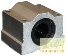
3. Linear bearing in housing, SCS16UU (4 holes), quantity 4pcs;
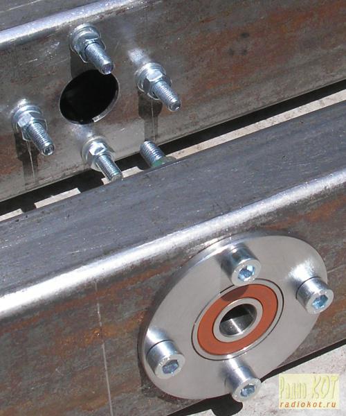
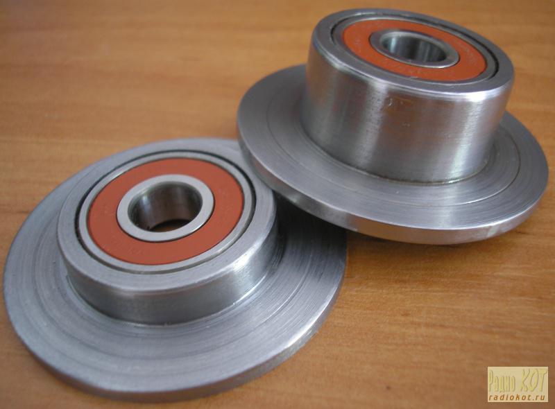
4. Bearing supports (bearing No. 6000 - 3 pcs.), Quantity 2 pcs, turned;
5. Trapezoid screw with cutting ends, length 740mm and caprolon nut;
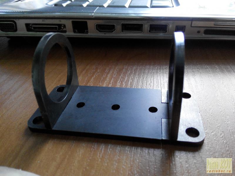
Let us dwell separately on the design of caprolon nuts. I came up with it myself. The nut is inserted into a detachable holder and is locked with thrust cotter pins, with a hexagon head.
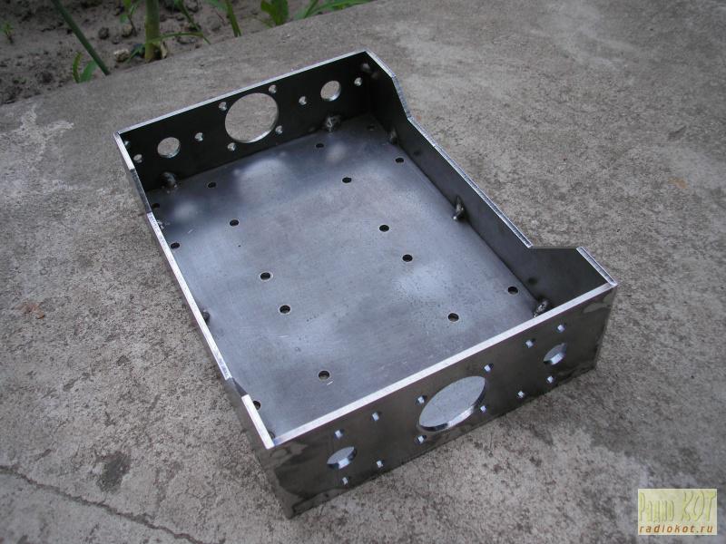
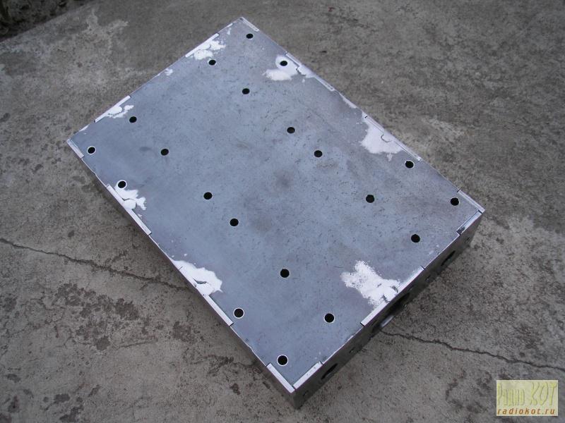
Now the Z axis. For welding, I screwed the "bottom" of the axis, through its holes with screws to the chipboard, so that it would not lead. Then he leaned four walls and pulled them together with clamps. I boiled it, inside in the corners with tacks, and on the outside, each “thorn” in 1-2 places (depending on the width). It cooled down, dismantled the screws and cleaned it (only from the outside).
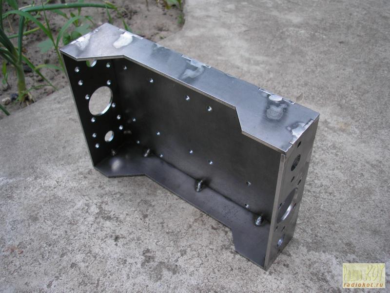
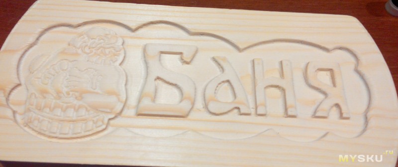
Nowadays, the production of small parts made of wood, for various structures, is becoming more and more frequent. Also in stores you can find a variety of beautiful three-dimensional paintings made on wood canvas. Such operations are performed using numerically controlled milling machines. The accuracy of parts or pictures made of wood is achieved through computer control, a specialized program.
Milling machine for wood processing numerical control is a highly professional machine, created according to last word technology.
All work consists in processing with a special wood cutter, which can be used to cut small parts from wood material, create beautiful drawings. The work is carried out by supplying signals to stepper motors, which, in turn, move the router along three axes.
Due to this, high-precision processing occurs. As a rule, such work cannot be done manually with such high quality. Therefore, CNC wood milling machines are a great find for carpenters.
purpose
Since ancient times, milling was intended for planing work with wood. But the engine of progress is moving strictly forward in our time, numerical control has been created for such machines. At this stage, the milling machine can perform a variety of actions that relate to wood processing:
- Cutting various parts from solid wood.
- Cutting off excess parts of the workpiece.
- Ability to make grooves and holes of various diameters.
- Drawing complex ornaments using a cutter.
- 3D Three-dimensional images on solid wood.
- Full-fledged furniture production and much more.
Whatever the task, it will be carried out with high precision and accuracy.
Tip: When working on homemade CNC equipment, you need to smoothly remove the thickness of the wood, otherwise your part will be damaged or burned by the cutter!
Variety
In the modern technological world, the following types of CNC wood milling machines are distinguished:
Stationary
These machines are placed in industries, as they are huge in size and weight. But such equipment is capable of manufacturing products in large volumes.
Manual
These are homemade devices or devices from ready-made kits. These machines can be safely installed in your garage or your own workshop. These include the following subspecies:
Equipment using portal, with numerical control
Directly, the milling cutter itself is able to move along two Cartesian axes X and Z. This type of machine has high rigidity when bending. The design of the portal milling machine with numerical control is quite simple in its execution. Many carpenters begin their knowledge of CNC machines from this subtype. However, in this case, the size of the workpiece will be limited by the size of the portal itself.
Numerically controlled and mobile gantry
The construction of this subtype is a little more complicated.
mobile portal
It is this type that moves the router along all three Cartesian axes, along X, Z and Y. In this case, it will be necessary to use a solid guide for the X axis, since all the heavy load will be directed to it.
With a mobile portal, it is very convenient to create printed circuit boards. On the Y axis, it is possible to process long parts.
The cutter moves along the Z axis.
Machine on which the milling part is able to move in a vertical direction
This subtype is usually used when refining production samples or when reworking drilling equipment in engraving and milling.
The working field, that is, the tabletop itself, has dimensions of 15x15 centimeters, which makes it impossible to process large parts.
This type is not very convenient to use.
Numerically controlled portalless
This type of machine is very complex in its design, but it is the most productive and convenient.
Workpieces can be processed up to five meters long, even if the X-axis is 20 centimeters.
This subtype is extremely unsuitable for the first experience, as it requires skills on this equipment.
Below we will consider the design of a hand-held CNC wood milling machine, we will analyze the principles of its operation. We learn how to do this brainchild and how such equipment is being adjusted.
Device and principle of operation
The main parts of the milling device are the following parts:
bed
Directly the design of the machine itself, on which all other parts are located.
caliper
A node that is a mount to support the movement of an automatic tool.
Desktop
The area where all the necessary work is done.
Spindle shaft or router
A tool that performs milling work.
Cutter for wood processing
A tool, or rather a device for a milling cutter, of various sizes and shapes, with the help of which wood is processed.
CNC
Let's just say the brain and heart of the whole structure. The software performs precise control of all work.
The work is program management. A specialized program is installed on the computer, it is she who converts the circuits loaded into it into special codes, which the program distributes to the controller, and then to stepper motors. Stepper motors, in turn, move the milling cutter along the coordinate axes Z, Y, X, due to which the processing of the wooden workpiece takes place.
Choice of accessories
The main step in the invention homemade milling machine is the choice of component parts. After all, choosing bad material, something can go wrong in
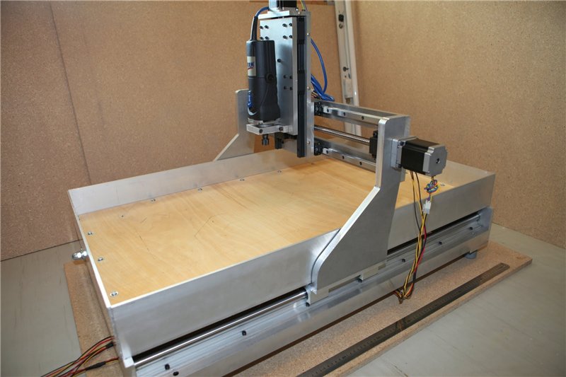
An example of an assembly from an aluminum frame.
the work itself. Usually simple materials are used, such as: aluminum, wood (solid, MDF), plexiglass. For the correct and accurate operation of the entire structure, it is important to develop the entire design of the calipers.
Tip: Before assembly do it yourself, it is necessary to check all already prepared parts for compatibility.
Check if there are any snags that will interfere. And most importantly, to prevent various kinds of fluctuations, as this will directly lead to poor-quality milling.
There are some assignments for the selection of work items that will help in the creation, namely:
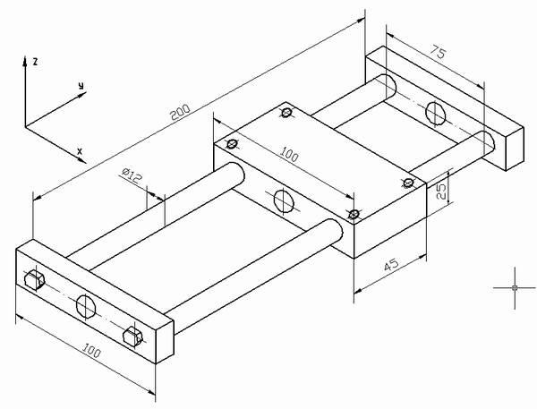
Guides
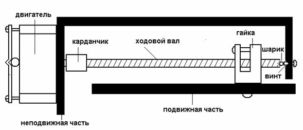
Scheme of CNC guides for a milling cutter.
For them, rods with a diameter of 12 millimeters are used. For the X axis, the length of the rod is 200 millimeters, and for the Y axis, the length is 90 millimeters.
The use of guides will allow high-precision installation of moving parts
caliper
caliper CNC milling machine.
Support assembly.
Textolite material can be used for these components. Pretty durable material of its kind. As a rule, the dimensions of the textolite pad are 25x100x45 millimeters.
Router locking block
An example of a frame for fixing a router.
You can also use a textolite frame. The dimensions directly depend on the tool you have.
Stepper motors or servo motors
Power Supply
Controller
An electronic board that distributes electricity to stepper motors to move them along axes.
Tip: When soldering the board, it is necessary to use capacitors and resistors in special SMD cases (aluminum, ceramics, and plastic are used to make cases for such parts). This will reduce the dimensions of the board, as well as the internal space in the design will be optimized.
Assembly
Scheme of a home-made machine with numerical control
The assembly will not take you too much time. The only thing is that the tuning process will be the longest in the entire manufacturing process.
To start
It is necessary to develop a diagram and drawings of the future numerical control machine.
If you do not want to do this, then you can download drawings from the Internet. For all sizes prepare all the necessary details.
Make all necessary holes
Designed for bearings and guides. The main thing is to keep everything required dimensions otherwise the operation of the machine will be disturbed. A diagram with a description of the location of the mechanisms is presented. It will give you a general idea, especially if you are collecting it for the first time.
When all the elements and parts of the mechanism are ready for you, you can safely proceed with the assembly. The first step is to assemble the equipment frame.
frame
Must be geometrically correct. All corners should be even and equal. When the frame is ready, you can mount the guide axles, desktop, calipers. When these elements are installed, you can install a router or a spindle.
The last step remains - electronics. Installing the electronics is the main step in the assembly. A controller is connected to the stepper motors installed on the machine, which will be responsible for their operation.
Next, the controller is connected to a computer on which a special control program should already be installed. Widely applied trademark Arduino, which manufactures and supplies hardware equipment.
With everything connected and ready, it's time to run a test piece. Any wood that will not go beyond the desktop is suitable for this. If your workpiece has been processed and everything is in order, then you can proceed to the full-fledged manufacture of one or another milling product.
Safety
Safety with milling equipment is the foundation of the basics. If you do not take care of yourself, you can end up in the hospital with serious injuries. All safety rules are the same, but the most basic ones will be listed below:
- You must ground your equipment to avoid electric shock.
- Keep children away from the machine.
- Do not eat or drink on the desktop.
- Clothing should be appropriate.
- Do not process bulky parts that exceed the size of the desktop, machine equipment.
- Do not throw various tools to the working area of the machine.
- Do not use material (metal, plastic, etc.).
Video reviews
Video review of parts for the machine and where to get them:
Video review of the wood milling machine:
Video review of electronics
Execution condition professional works for wood is the presence of a CNC milling machine. Commercially available roads and not everyone can afford it. Therefore, many make them with their own hands, saving money and enjoying the creative process.
There are two options for the manufacture of mini machines for milling wood:
- purchase of a set of parts and its manufacture (Modelist kits costing from 40 to 110 thousand rubles);
- make it with your own hands.
Consider the manufacture of mini CNC milling machines with your own hands.
Choice of design features
The list of actions in the development, manufacture of a mini device for wood milling is as follows:
- Initially, you need to decide what kind of work we are talking about. This will tell you what dimensions and thicknesses of parts can be processed on it.
- Make a layout and an estimated list of parts for a homemade desktop machine for DIY manufacturing.
- Select software to bring it into working condition so that it works according to a given program.
- Purchase the necessary components, parts, products.
- Having drawings, make the missing elements with your own hands, assemble and debug the finished product.
Design
A homemade machine consists of the following main parts:
- bed with a table placed on it;
- calipers with the ability to move the cutting cutter in three coordinates;
- spindle with cutter;
- guides for moving calipers and portal;
- a power supply unit that provides electricity to the motors, a controller or a switching board using microcircuits;
- drivers to stabilize the work;
- sawdust vacuum cleaner.
Guides are installed on the frame to move the portal along the Y axis. Guides are placed on the portal to move the caliper along the X axis. The spindle with the cutter is mounted on the caliper. It moves along its guides (Z-axis).
The controller and drivers provide automation of the CNC machine by transmitting commands to the electric motors. Usage software package Kcam allows you to use any controller and provides motor control in accordance with the part drawing entered into the program.
The design must be made rigid in order to withstand the working forces that arise during operation and not lead to vibrations. Vibrations will lead to a decrease in the quality of the resulting product, tool breakage. Therefore, the dimensions of the fasteners must ensure the solidity of the structure.
A homemade CNC milling machine is used to obtain a three-dimensional 3D image on wood detail. It is attached to the table of this unit. It can also be used as an engraver. The design ensures the movement of the working body - the spindle with the cutter installed in accordance with the specified program of actions. The movement of the caliper along the X and Y axes occurs along polished guides using stepper motors.
Moving the spindle along the vertical Z axis allows you to change the depth of processing on the created drawing on the tree. To obtain a 3D relief drawing, you need to make drawings. It is advisable to use different kinds cutters that will allow you to get the best image display options.
Selection of components
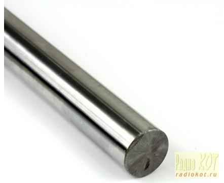
For guides, steel rods D = 12 mm are used. For better movement of the carriages, they are ground. Their length depends on the size of the table. You can use hardened steel rods from a dot matrix printer.
Stepper motors can be used from there. Their parameters: 24 V, 5 A.
It is desirable to provide fixing of cutters with a collet.
It is better to use a factory-made power supply for a home-made mini milling machine, since performance depends on it.
The controller needs to use capacitors and resistors in SMD packages for surface mounting.
Assembly
To assemble a home-made machine for milling 3D wood parts with your own hands, you need to make drawings, prepare essential tool, accessories, make the missing parts. After that, you can start assembling.
The do-it-yourself assembly sequence of a mini CNC machine with 3D processing consists of:
- caliper guides are installed in the sidewalls together with the carriage (without screws).
- the carriages are moved along the guides until their motion becomes smooth. Thus, the holes in the caliper are lapped.
- tightening bolts on calipers.
- fixing assembly units on the machine and installing screws.
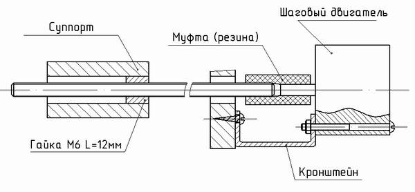
- installation of stepper motors and their connection with screws using couplings.
- the controller is allocated in a separate block to reduce the influence of operating mechanisms on it.
A homemade CNC machine after assembly must be tested! Testing 3D processing is carried out by using sparing modes to identify all problems and fix them.
Operation in automatic mode is provided by software. Advanced computer users can use power supplies and drivers for controllers, stepper motors. The power supply converts the incoming alternating current (220 V, 50 Hz) into direct current necessary to power the controller and stepper motors. For them, machine control from a personal computer passes through the LPT port. Working programs are Turbo CNC and VRI-CNC. CorelDRAW and ArtCAM graphic editor programs are used to prepare the drawings necessary for implementation in a tree.
Results
Homemade mini CNC milling machine for 3D parts is easy to operate, ensures accuracy and quality of processing. If you need to do more complex work, you need to use stepper motors of greater power (for example: 57BYGH-401A). In this case, to move the calipers, you need to use toothed belts to rotate the screws, and not a clutch.
The installation of the power supply (S-250-24), switching board, drivers can be done in the old case from the computer, modifying it. It can be equipped with a red "stop" button for emergency shutdown of equipment.
If you find an error, please highlight a piece of text and click Ctrl+Enter.
A CNC router can be a great helper in small-scale production or home repairs. The cost of factory CNC milling machines (cnc) is quite high, so some craftsmen successfully create them with their own hands according to unique drawings.
Making a homemade cnc machine with your own hands is not easy, sometimes it takes several months.
Machine design
The bed for a homemade metal milling machine is easiest to make from a square pipe 80 x 80 mm, quite low. The low height makes the device quite stable and prevents vibration. The stand for fixing the rails is also made of rectangular metal pipe 60 x 20 mm. The bed is bolted, as welded joints deform the structure. Bolted fasteners allow you to set the device exactly on the level, the contact area is large, the fastening is reliable and fairly rigid, without backlash.
The size of the working field of a home-made machine must be made from 32 x 35 cm. The length of the guide shafts along Y and X is 1.6 cm, along Z - 1 cm.
Guides are best made profile, otherwise they will sag along the X axis.
Plain bearings are better to choose industrial, albeit the most inexpensive. Their use will reduce the likelihood of backlash.
The Z axis is mounted on a screw gear, as it is quite heavy. To transmit torsion to the lead screw from the Z-axis, a toothed belt with a width of 10 mm is used. Such a scheme allows you to reduce the beating and facilitate the placement of the stepper motor relative to the travel screw. Reduces machine weight and saves vertical space.
The axle itself is made from an aluminum plate, and two stepper motors are installed behind it. Their purpose is to transfer torsion to the Z-axis screw by means of a toothed belt, another motor transmits movement along the X-axis with a belt. The Z-axis lead screw can be made from a construction stud.
If instead of a belt a screw gear is made in the drawing, the speed will increase to 850 rpm and the accuracy of the homemade cnc machine tool. But this design is much more expensive.
If you plan to water-cool the spindle, you should also provide a water pump, as well as a set of rubber tubes.
Engine and software
For a homemade CNC milling machine (they are also called cnc), a stepper motor with a torque of 18 kg / cm is suitable. Such a motor is sufficient for a spindle with a power of 1.5 kilowatts. It will be possible to process parts from soft metals and simple work on carbon steel.
The controller, frequency convector and motherboard can be installed in a single protective box. Although many are afraid of interference, they are quite rare. Such a control center is prone to overheating in hot weather!
CNC milling machines, assembled by hand according to drawings, work under the guidance of Linux. Some drivers will have to be written by hand, for example, for a stepper motor with microstepping. Controllers with USB output do not work under Linux, this should be taken into account when choosing them. You need to buy a four-axis controller and make the appropriate settings.
Ready set for machine assembly
Most craftsmen who assemble the machine with their own hands are faced with the need to purchase many finished parts. As a result, the price homemade device may be higher than factory. The process of self-assembly is very lengthy, and the result is often disappointing. Often, craftsmen remake several times machines assembled without drawings and calculations, bringing their work to the desired standard.
There is a possibility in one working day with the help of wrench and screwdrivers to make a CNC router with your own hands using a ready-made kit - a kind of simple constructor for adults, containing absolutely all the details and drawings. The set is a guarantee of the high quality of the future machine.
The device and testing of a homemade milling cutter:
A set with which you can assemble your CNC milling machine.
Ready-made machine tools are sold in China, a review of one of them has already been published on Muska. We will assemble the machine ourselves. Welcome…
UPD: file links
I will still give a link to a review of the finished machine from AndyBig. I will not repeat myself, I will not quote his text, we will write everything from scratch. The title only lists a set with engines and a driver, there will be more parts, I'll try to give links to everything.
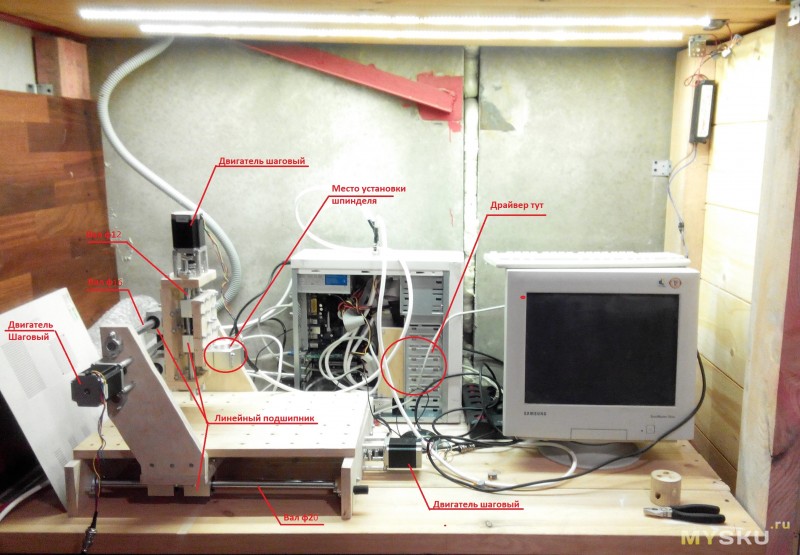
And this ... I apologize in advance to the readers, I did not specifically take photos in the process, because. at that moment I was not going to do a review, but I will raise a maximum of photos of the process and try to give a detailed description of all the nodes.
The purpose of the review is not so much to brag as to show the opportunity to make an assistant for yourself. I hope this review will give someone an idea, and it is possible not only to repeat, but also to make it even better. Go…
How the idea was born:
It so happened that I have been associated with drawings for a long time. Those. my professional activity is closely connected with them. But it's one thing when you make a drawing, and then completely different people bring the design object to life, and it's quite another when you bring the design object to life yourself. And if with building things I seem to be doing okay, then with modeling and other applied arts not really.
So for a long time there was a dream from an image drawn in AutoCAD, to make a whack - and it is in kind in front of you, you can use it. This idea slipped from time to time, but could not take shape in anything concrete, until ...
Until I saw REP-RAP three or four years ago. Well, the 3D printer was a very interesting thing, and the idea to assemble myself took a long time to take shape, I collected information about different models about the pros and cons different options. At one point, by clicking on one of the links, I got to a forum where people were sitting and discussing not 3D printers, but CNC milling machines. And from here, perhaps, the hobby begins its journey.
Instead of theory
In a nutshell about CNC milling machines (I write in my own words intentionally, without copying articles, textbooks and manuals).
A milling machine works exactly the opposite of a 3D printer. In the printer, step by step, layer by layer, the model is built up by fusing polymers, in a milling machine, with the help of a cutter, “everything superfluous” is removed from the workpiece and the required model is obtained.
To operate such a machine, you need the necessary minimum.
1. Base (body) with linear guides and transmission mechanism (can be screw or belt)
2. Spindle (I see someone smiled, but that's what it's called) - the actual engine with a collet into which a working tool is installed - a milling cutter.
3. Stepper motors - motors that allow controlled angular movements.
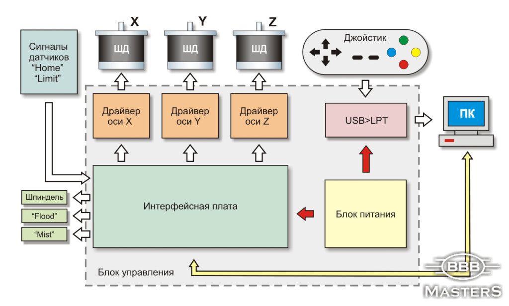
4. Controller - a control board that transmits voltage to the motors in accordance with the signals received from the control program.
5. Computer with installed control program.
6. Basic drawing skills, patience, desire and good mood.))
The points:
1. Base.
by configuration:
I will divide into 2 types, there are more exotic options, but the main 2:
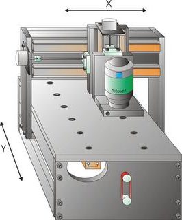
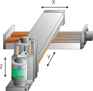
With movable portal:
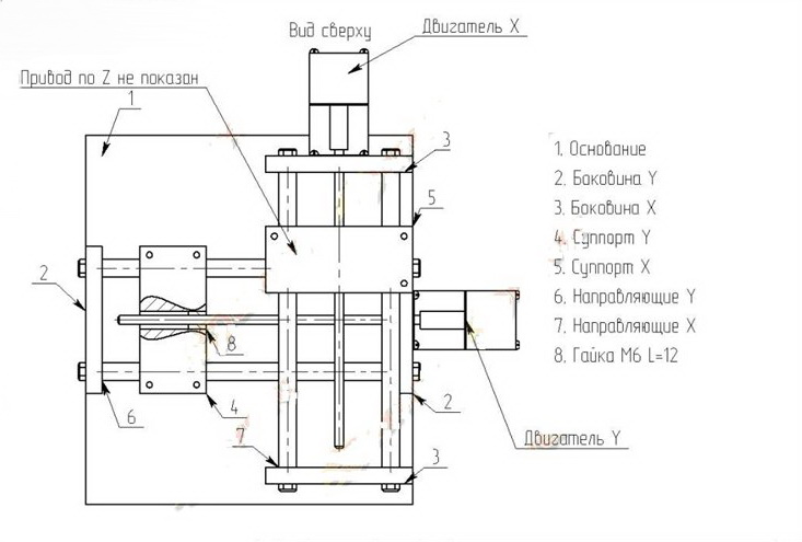
Actually, the design I have chosen, it has a base on which guides are fixed along the X axis. A portal moves along the X-axis guides, on which the Y-axis guides are located, and the Z-axis node moving along it.
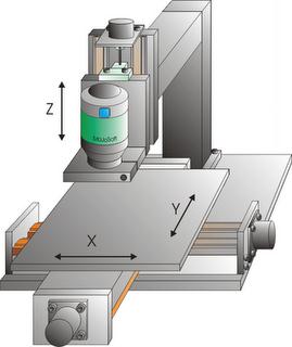
With static portal
This design also represents itself as a body, which is also a portal on which the Y-axis guides are located, and the Z-axis node moving along it, and the X-axis is already moving relative to the portal.
By material:
The case can be made of different materials, the most common are:
- duralumin - has a good ratio of mass, rigidity, but the price (just for a hobby homemade product) is still depressing, although if there are views on the machine for making serious money, then there are no options.
- plywood - good rigidity with sufficient thickness, light weight, the ability to process with anything :), well, actually the price, a sheet of plywood 17 is now quite inexpensive.
- steel - often used on machines with a large processing area. Such a machine, of course, must be static (not mobile) and heavy.
- MFD, plexiglass and monolithic polycarbonate, even chipboard - I also saw such options.
As you can see, the design of the machine itself is very similar to both a 3D printer and laser engravers.
I deliberately do not write about the designs of 4, 5 and 6-axis milling machines, because. on the agenda is a homemade hobby machine.
2. Spindle.
Actually, spindles come with air and water cooling.
Air-cooled are cheaper in the end, because. for them it is not necessary to block an additional water circuit, they work a little louder than water ones. Cooling is provided by a rear-mounted impeller, which at high speeds creates a noticeable air flow that cools the motor housing. How more powerful engine, the more serious the cooling and the greater the air flow, which may well inflate in all directions
dust (shavings, sawdust) of the workpiece.
Water cooled. Such a spindle works almost silently, but in the end, anyway, the difference between them in the process of work cannot be heard, since the sound of the material being processed by the cutter will block it. There is no draft from the impeller, in this case, of course, but there is an additional hydraulic circuit. In such a circuit, there must be pipelines, a pump for pumping liquid, as well as a place for cooling (radiator with airflow). Usually not water is poured into this circuit, but either TOSOL or Ethylene glycol.
There are also spindles of various capacities, and if low-power ones can be connected directly to the control board, then motors with a power of 1 kW or more must be connected through the control unit, but this is not about us.))
Yes, still often homemade machines install direct grinders, or milling machines with a removable base. Such a decision can be justified, especially when performing work of a short duration.
In my case, a 300W air-cooled spindle was chosen.
3. Stepper motors.
The most widely used motors are 3 sizes
NEMA17, NEMA23, NEMA 32
they differ in size, power and working moment
NEMA17 are usually used in 3D printers, they are too small for a milling machine, because. you have to carry a heavy portal, to which a lateral load is additionally applied during processing.
NEMA32 for such a craft is unnecessary, besides, you would have to take another control board.
my choice fell on NEMA23 with maximum power for this board - 3A.
Also, people use steppers from printers, but since. I didn’t have them either and still had to buy, I chose everything in the kit.
4. Controller
A control board that receives signals from the computer and transmits voltage to stepper motors that move the axes of the machine.
5. Computer
You need a separate computer (possibly very old) and there are, perhaps, two reasons for this:
1. It is unlikely that you will decide to place a milling machine near the place where you are used to reading the Internet, playing toys, keeping accounts, etc. Simply because the milling machine is loud and dusty. Usually the machine is either in the workshop or in the garage (better heated). My machine is in the garage, it is mostly idle in winter, because. no heating.
2. For economic reasons, computers are usually used that are no longer relevant for home life - heavily used :)
Requirements for the car by and large about nothing:
- from Pentium 4
- the presence of a discrete video card
- RAM from 512MB
- the presence of an LPT connector (I won’t say anything about USB, I haven’t studied the news yet because of the driver that works on LPT)
such a computer is either taken from the pantry, or, as in my case, is bought for next to nothing.
Due to the low power of the machine, we try not to install additional software, i. axle only and control program.
Next are two options:
- install windows XP (it's a weak computer, remember right?) and the MATCH3 control program (there are others, but this is the most popular)
- we put niks and Linux CNC (they say that everything is also very good, but I didn’t master niks)
I will add, perhaps, in order not to offend overly wealthy people, that it is quite possible to put not a fourth stump, but some kind of ai7 - please, if you like it and can afford it.
6. Basic drawing skills, patience, desire and good mood.
Here in a nutshell.
To operate the machine, you need a control program (essentially a text file containing the coordinates of movements, movement speed and acceleration), which in turn is prepared in a CAM application - usually ArtCam, in this application the model itself is prepared, its dimensions are set, and a cutting tool is selected.
I usually take a slightly longer route, make a drawing, and then AutoCad, saving it *.dxf, upload it to ArtCam and prepare the UE there.
Well, let's start the process of creating your own.
Before designing the machine, we take for starting points a few points:
- Axle shafts will be made of construction studs with M10 thread. Of course, there are undoubtedly more technological options: a shaft with a trapezoidal thread, a ball screw (ball screw), but you need to understand that the price of the issue leaves much to be desired, and for a hobby machine, the price is generally space. However, over time, I'm going to upgrade and replace the hairpin with a trapezoid.
- The material of the machine body is 16mm plywood. Why plywood? Available, cheap, cheerful. There are actually many options, someone makes from duralumin, someone from plexiglass. I prefer plywood.
Making a 3D model: 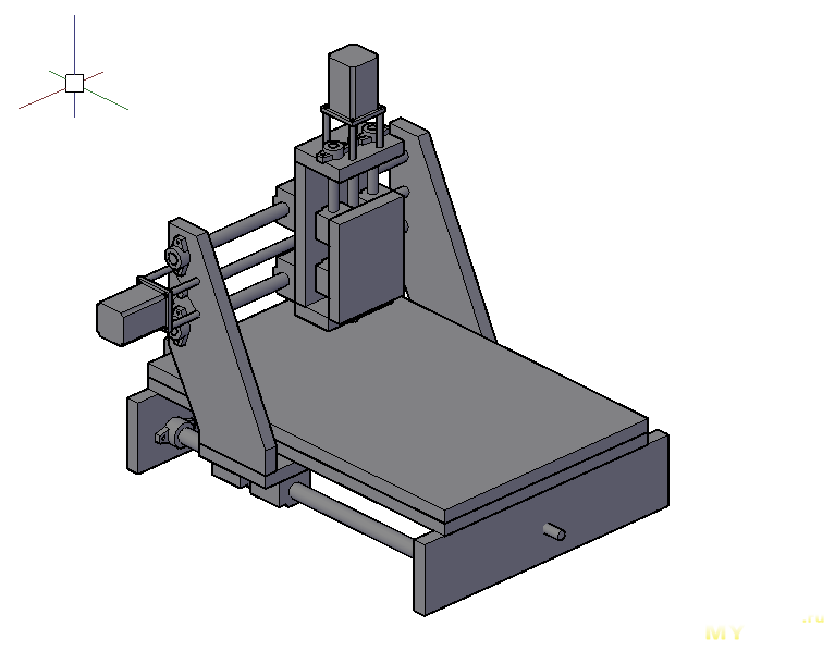
Reamer: 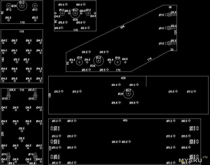
Then I did this, there was no picture left, but I think it will be clear. I printed out a scan on transparent sheets, cut them out and pasted them onto a sheet of plywood.
Sawed pieces and drilled holes. Of the tools - a jigsaw and a screwdriver.
There is one more little trick that will make life easier in the future: before drilling holes, squeeze all paired parts with a clamp and drill through, so you get holes that are equally located on each part. Even if a slight deviation occurs during drilling, the internal parts of the connected parts will match, and the hole can be reamed a little.
In parallel, we make a specification and start ordering everything.
what happened to me:
1. The set specified in this review includes: stepper motor control board (driver), NEMA23 stepper motors - 3 pcs., 12V power supply, LPT cord and cooler.
2. Spindle (this is the simplest, but nevertheless does its job), fasteners and a 12V power supply.
3. Used computer Pentium 4, most importantly, the motherboard has LPT and a discrete video card + CRT monitor. I took it to Avito for 1000 rubles.
4. Steel shaft: Ф20mm - L=500mm - 2pcs, Ф16mm - L=500mm - 2pcs, Ф12mm - L=300mm - 2pcs.
I took it here, at that time in St. Petersburg it turned out to be more expensive to take. Came within 2 weeks.
5. Linear bearings: f20 - 4 pcs., f16 - 4 pcs., f12 - 4 pcs.
20
16
12
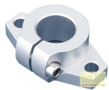
6. Fastenings for shafts: f20 - 4 pcs., f16 - 4 pcs., f12 - 2 pcs.
20
16
12
7. Caprolon nuts with M10 thread - 3 pcs.
I took along with the shafts on duxe.ru
8. Rotation bearings, closed - 6 pcs.
In the same place, but the Chinese also have a lot of them
9. PVA wire 4x2.5
it's offline
10. Cogs, dowels, nuts, clamps - a bunch.
This is also offline, in hardware.
11. A set of cutters was also bought
So, we order, wait, cut and collect. 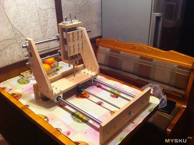
Initially, the driver and power supply for it were installed in the case with the computer together. ![]()
Later it was decided to place the driver in a separate case, it just appeared. 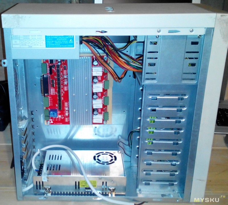
Well, the old monitor somehow changed to a more modern one. 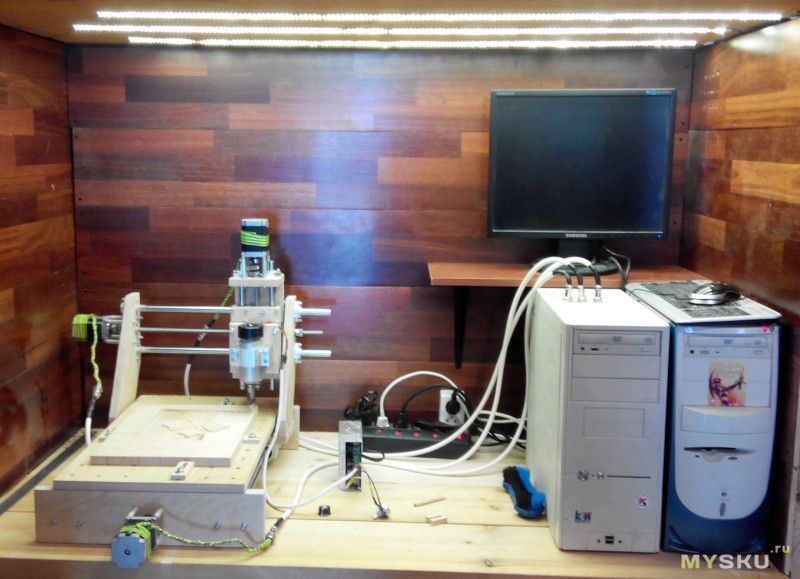
As I said at the beginning, I never thought that I would write a review, so I am attaching photos of the nodes, and I will try to explain the assembly process.
First, we assemble three axles without screws in order to align the shafts as accurately as possible.
We take the front and rear walls of the housing, fasten the flanges for the shafts. We string 2 linear bearings on the X axis and insert them into the flanges. 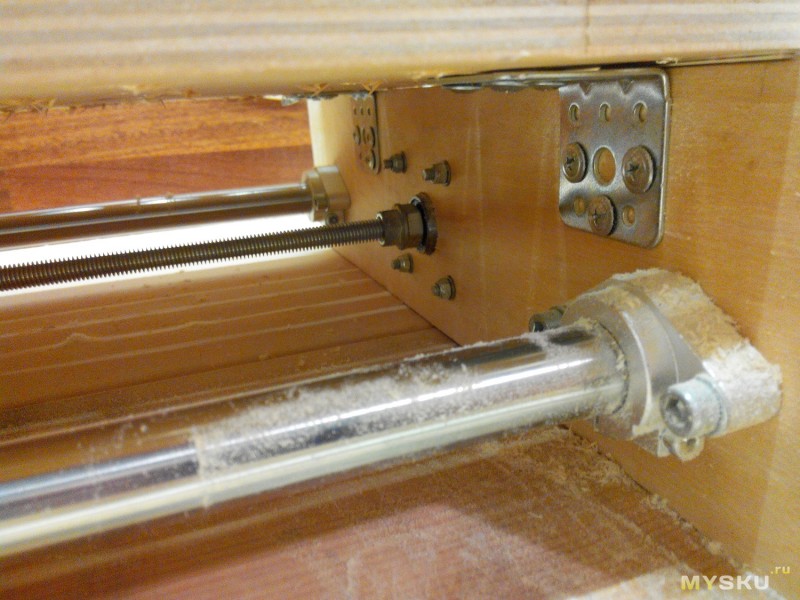
We fasten the bottom of the portal to the linear bearings, we try to roll the base of the portal back and forth. We are convinced of the curvature of our hands, we disassemble everything and drill holes a little.
Thus, we get some freedom of movement of the shafts. Now we bait the flanges, insert the shafts into them and move the base of the portal back and forth to achieve a smooth glide. We tighten the flanges.
At this stage, it is necessary to check the horizontalness of the shafts, as well as their alignment along the Z axis (in short, so that the distance from the assembly table to the shafts is the same) so as not to fill up the future work plane later.
We figured out the X axis.
We fasten the portal racks to the base, for this I used furniture barrels. 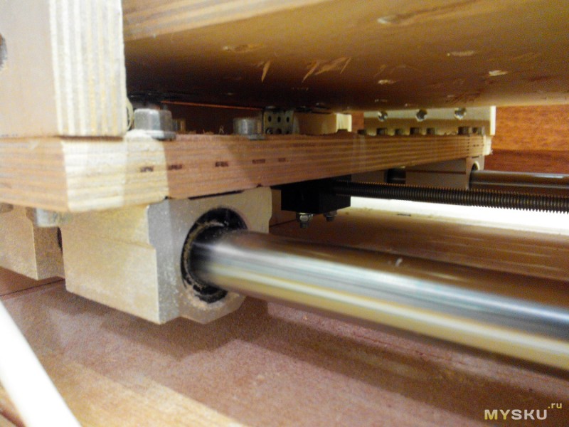
Fasten the flanges for the Y axis to the uprights, this time from the outside: 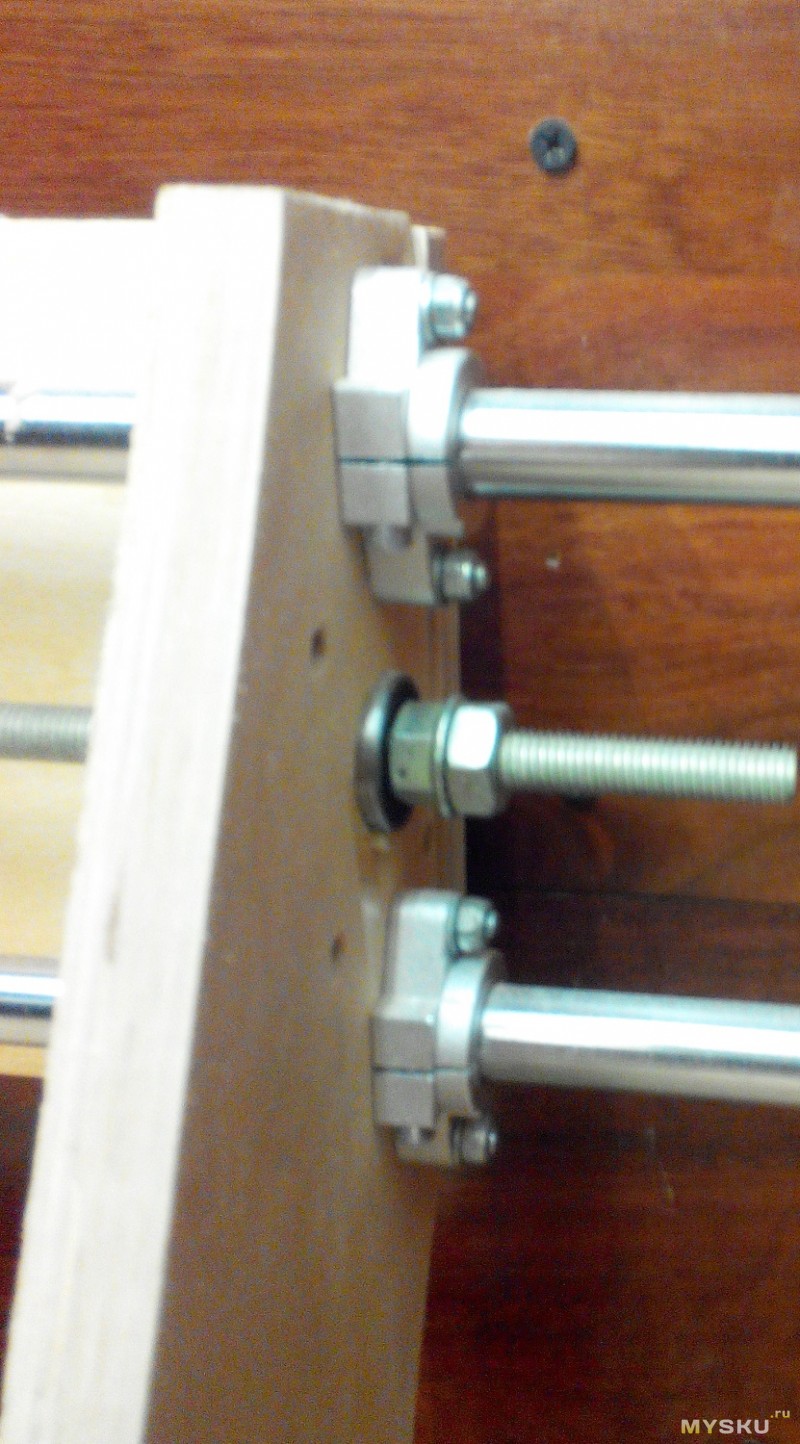
We insert shafts with linear bearings.
We fix the back wall of the Z axis.
We repeat the process of adjusting the parallelism of the shafts and fix the flanges.
We repeat the same process with the Z axis.
We get a rather funny design that can be moved with one hand along three coordinates.
An important point: all axes should move easily, i.e. slightly tilting the structure, the portal itself should move freely, without any squeaks and resistance.
Next, attach the lead screws.
We cut off the M10 construction stud of the required length, screw the caprolon nut approximately in the middle, and 2 M10 nuts on each side. It is convenient for this, after tightening the nuts a little, clamp the stud into the screwdriver and, holding the nuts, tighten.
We insert the bearings into the sockets and push the studs into them from the inside. After that, we fix the studs to the bearing with nuts on each side and counter with the second so that they do not come loose.
We fasten the caprolon nut to the base of the axle.
We clamp the end of the stud into the screwdriver and try to move the axis from start to finish and return.
Here we have a couple more joys waiting for us:
1. The distance from the axis of the nut to the base in the center (and most likely at the time of assembly the base will be in the middle) may not coincide with the distance in the extreme positions, because shafts under the weight of the structure can bend. I had to put cardboard along the X axis.
2. Shaft travel can be very tight. If you have eliminated all distortions, then tension can play a role, here it is necessary to catch the moment of tension of fixing with nuts to the installed bearing.
Having dealt with the problems and having received free rotation from start to finish, we proceed to install the remaining screws.
We attach stepper motors to the screws:
In general, when using special screws, whether it be a trapezoid or a ball screw, the ends are processed on them and then the connection to the engine is very conveniently made with a special coupling. 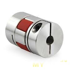
But we have a construction stud and had to think about how to fix it. At that moment, I came across a cut gas pipe, and applied it. It directly “winds” onto the hairpin on the engine, enters the grinding, tightened it with clamps - it holds very well. ![]()
To fix the engines, I took an aluminum tube and cut it. Adjusted with washers.
To connect the engines, I took the following connectors: 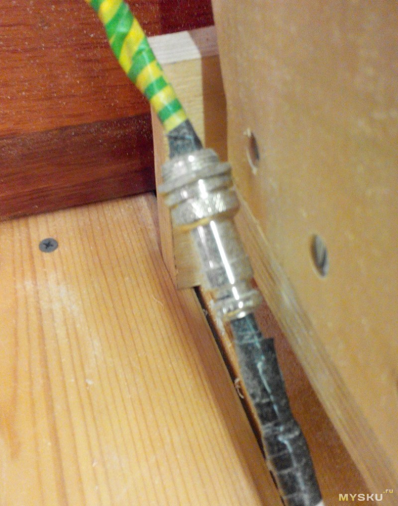
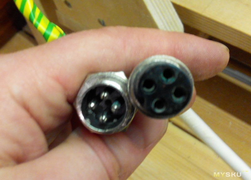
Sorry, I don’t remember what they are called, I hope someone in the comments will tell you.
GX16-4 connector (thanks Jager). I asked a colleague to buy in an electronics store, he just lives nearby, but it turned out to be very inconvenient for me to get there. I am very pleased with them: they hold them securely, they are designed for a higher current, you can always disconnect them.
We put working field aka the sacrificial table.
We connect all the motors to the control board from the review, connect it to a 12V PSU, connect to the computer with an LPT cable.
Install MACH3 on PC, make settings and try!
About the setting separately, perhaps, I will not write. It could go on for a couple more pages.
I have a whole joy, the video of the first launch of the machine has been preserved:
Yes, when this video was moving along the X axis, there was a terrible bounce, unfortunately I don’t remember exactly, but in the end I found either the washer dangling, or something else, in general, it was solved without problems.
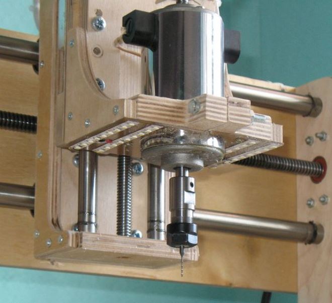
Next, you need to put the spindle, while ensuring its perpendicularity (simultaneously in X and Y) to the working plane. The essence of the procedure is this, we attach a pencil to the spindle with electrical tape, thus indenting from the axis is obtained. With a smooth lowering of the pencil, he begins to draw a circle on the board. If the spindle is littered, then it turns out not a circle, but an arc. Accordingly, it is necessary to achieve alignment by drawing a circle. A photo from the process has been preserved, the pencil is out of focus, and the angle is not the same, but I think the essence is clear: 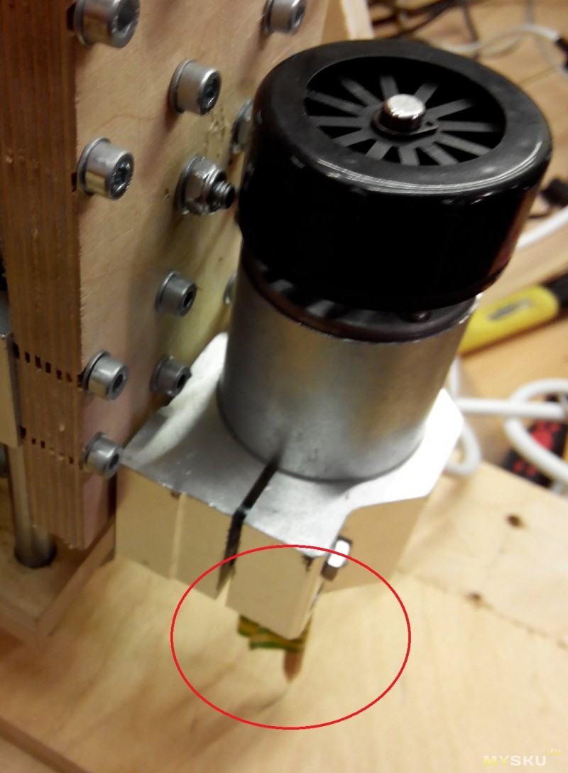
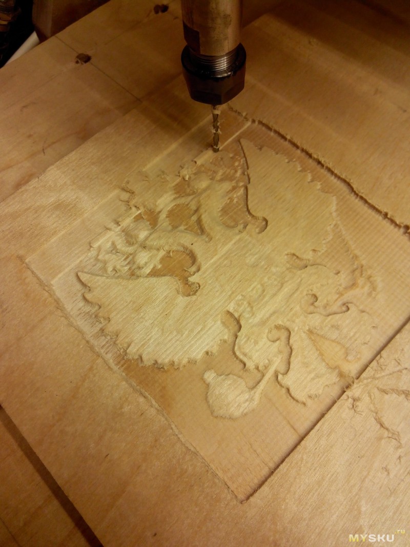
We find a finished model (in my case, the coat of arms of the Russian Federation), prepare the UE, feed it to MACH and go!
Machine operation:
photo in progress:
Well, of course we go through the initiation))
The situation is both funny and generally understandable. We dream of building a machine and immediately sawing something super cool, but in the end we understand that this time will just take a lot of time.
In a nutshell:
With 2D processing (simply sawing out), a contour is set, which is cut out in several passes.
With 3D processing (here you can immerse yourself in a holivar, some argue that this is not 3D but 2.5D, since the workpiece is processed only from above), a complex surface is set. And the higher the accuracy of the desired result, the thinner the cutter is used, the more passes of this cutter are needed.
To speed up the process, roughing is used. Those. first, the main volume is sampled with a large cutter, then finishing with a thin cutter is started.
Next, we try, set up, experiment, etc. The 10000 hour rule works here too ;)
Perhaps I will no longer bore you with a story about the construction, tuning, etc. It's time to show the results of using the machine - the product. 
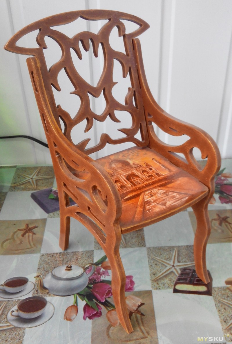

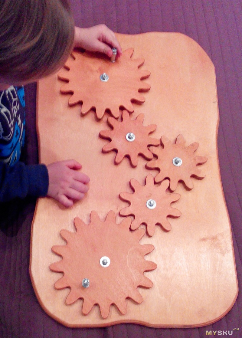
As you can see, these are mostly sawn contours or 2D processing. It takes a lot of time to process three-dimensional figures, the machine is in the garage, and I stop by there for a short time.
Here they will rightly notice me - but on ... to build such a bandura, if you can cut a figure with a U-shaped jigsaw or an electric jigsaw?
It is possible, but this is not our method. As you remember, at the beginning of the text, I wrote that it was the idea to make a drawing on a computer and turn this drawing into a product that prompted the creation of this beast.
Writing a review finally pushed me to upgrade the machine. Those. the upgrade was planned earlier, but "hands did not reach." The last change before this was the organization of the house for the machine: 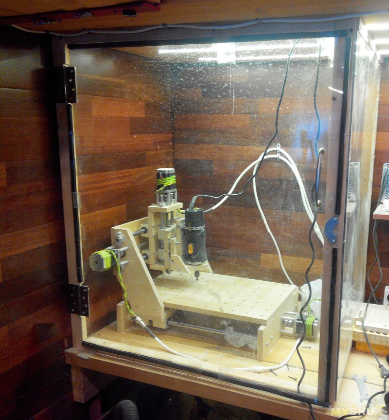
Thus, in the garage, when the machine is running, it has become much quieter and much less dust flies.
The last upgrade was the installation of a new spindle, more precisely, now I have two interchangeable bases:
1. With Chinese 300W spindle for fine work: 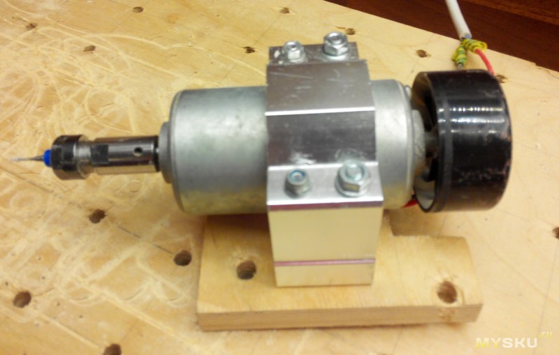
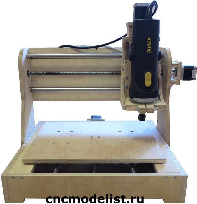
2. With a domestic, but no less Chinese milling cutter "Enkor" ... 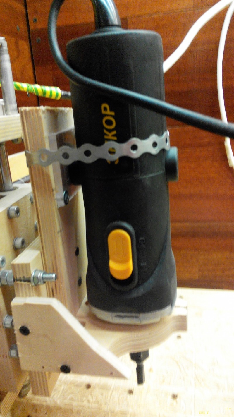
With the new router came new possibilities.
Faster processing, more dust.
Here is the result of using a semi-circular groove cutter: 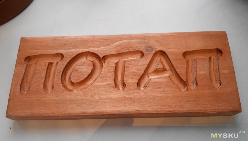
Well, especially for MYSKU
Simple straight groove cutter: ![]()
Process video:
On this I will curtail, but according to the rules it would be necessary to take stock.
Minuses:
- Expensive.
- For a long time.
- From time to time you have to solve new problems (they turned off the light, pickups, something unraveled, etc.)
Pros:
- The process of creation. Only this already justifies the creation of the machine. The search for solutions to emerging problems and implementation is what, instead of sitting on your butt, you get up and go to do something.
- Joy at the moment of giving gifts made with your own hands. Here it must be added that the machine does not do all the work itself :) in addition to milling, it is still necessary to process it, sand it, paint it, etc.
Thank you very much if you are still reading. I hope that my post, even if it does not incite you to create such (or another) machine, will broaden your horizons and give food for thought. I also want to say thank you to those who persuaded me to write this opus, without it I didn’t have an upgrade, apparently, so everything is in the black.
I apologize for the inaccuracies in the wording and any lyrical digressions. Much had to be cut, otherwise the text would have turned out to be simply immense. Clarifications and additions are naturally possible, write in the comments - I will try to answer everyone.
Good luck in your endeavors!
Promised file links:
- machine drawing,
- sweep,
format is dxf. This means that you can open the file with any vector editor.
The 3D model is detailed by 85-90 percent, I did many things, either at the time of preparing the scan, or in place. Please understand and forgive.)


How to understand: will the kitten be fluffy?
What kind of light alcohol can be drunk for pregnant women: the consequences of drinking
Why do the legs swell in the ankles and ankles of the feet in pregnant women: causes and methods of treatment
The wedding of Prince Harry and Meghan Markle: scandalous and secret details of the marriage (photo) The future marriage of Prince Harry year NTV
How to close white plums for the winter