The main task that must be solved when creating any electrical installation is to ensure its electrical safety. Regulatory documents provide for a set of measures to protect people and animals from damage electric shock, which should be provided for when designing an electrical installation and its installation.
Under the conductor in the regulatory documentation is understood a conductive part (a part capable of conducting electric current), designed to conduct an electric current of a certain value. In electrical installations of buildings, linear, neutral, protective and some other conductors are used.
Protective conductors (PE) used in electrical installations to protect people and animals from electric shock. Protective conductors, as a rule, have an electrical connection with the grounding device and therefore, in normal mode, the electrical installations of the building are at the potential of the local earth.
Protective conductors are connected to open conductive parts, with which a person has multiple electrical contacts.
Therefore, when installing the electrical installation of a building, it is very important not to confuse protective conductors with linear conductors in order to exclude a situation where a person who touches the case, for example, a refrigerator, to which a phase conductor is erroneously connected, will be shocked. The unique color identification of the protective conductors is designed to drastically reduce these errors.
In TN-C, TN-S, TN-C-S systems, the protective conductor is connected to a grounded live part of the power source, for example, to the grounded neutral of a transformer. It is called zero protective conductor.
In electrical installations of buildings, they are also used combined neutral protective and working conductors (PEN-conductors), which combine the functions of both zero protective and neutral (zero working) conductors. According to their purpose, protective conductors also include grounding conductors and potential equalization protective conductors.
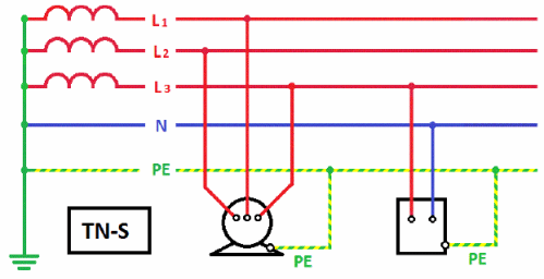
Zero protective conductor (PE - conductor in the TN-S system) is a conductor connecting grounded parts (open conductive parts) with a solidly grounded neutral point of a three-phase current power source or with a grounded output of a single-phase current power source, or with a grounded midpoint of a power source in networks direct current.The zero protective conductor should be distinguished from the zero working and PEN conductors.
Zero working conductor(N - conductor in the TN-S system) - a conductor in electrical installations with voltage up to 1 kV, designed to power electrical consumers connected to a solidly grounded neutral point of a generator or transformer in three-phase current networks, with a solidly grounded output of a single-phase current source, with a solidly grounded source point in DC networks current.
Combined zero protective and zero working conductor (PEN - conductor in the TN-C system) - a conductor in electrical installations with voltage up to 1 kV, combining the functions of a zero protective and zero working conductor.

Grounding conductors are integral part grounding device of the electrical installation of the building. They provide the electrical connection of the earth electrode with the main earth bus, to which, in turn, other protective conductors of the building's electrical installation are connected.
Protective grounding is a deliberate electrical connection to the ground or its equivalent of metal non-current-carrying parts that may become energized due to a short to the case and for other reasons (inductive effect of neighboring live parts, potential removal, lightning discharge, etc.). The equivalent of land can be the water of a river or sea, coal in a quarry, etc.
Purpose protective earth- elimination of the danger of electric shock in case of touching the body of the electrical installation and other non-current-carrying metal parts that are energized due to a short to the body and for other reasons.
Potential equalization conductors are used in electrical installations of buildings and in buildings to perform potential equalization (connecting open and third-party conductive parts to each other in order to ensure equipotentiality), which is usually designed to protect people and animals from electric shock. Therefore, in most cases, these conductors are potential equalization protective conductors.
In accordance with the requirements of GOST R 50462, yellow and green color can be used in a combination of yellow-green, which is used exclusively for the designation of protective (neutral protective) conductors (PE). Application for identification of conductors yellow color or green are not allowed if there is a risk of mixing said colors with the combination of yellow and green.
Based on the requirements set forth in GOST R 50462, amendments were made to the PUE establishing the following color marking of electrical wiring conductors:
a two-color combination of yellow-green color should indicate protective and neutral protective conductors;
blue color should be used to identify zero working conductors;
a two-color combination of yellow-green along the entire length of the conductor with blue marks at its ends, which are applied during installation, must be used to identify PEN conductors.
In accordance with the requirements of GOST R IEC 245-1, GOST R IEC 60227-1 and GOST R IEC 60173, the combination of yellow and green colors should only be used to indicate that insulated cable core that is intended for use as a protective conductor. The combination of yellow and green shall not be used to identify other cable cores.
The FORUMHOUSE website published an article " Construction of grounding systems: diagrams, parameters, materials used and additional equipment - theory and practice from FORUMHOUSE users» (see https://www.forumhouse.ru/articles/engineering-systems/7266). The article contains incorrect information about the types of system grounding (see) and their application, the separation of the PEN conductor, the implementation of grounding devices. Consider some of the mistakes made in the information about the separation of the PEN conductor.
The article says: " It's about dividing the incoming neutral wire, which leads to consumer in TN-C systems and separated when creating the TN-C-S system. A similar division is shown in the diagram.
TN-C-S system design
».
We read further: " Separation of the PEN conductor is carried out according to the following scheme:
For separation, two tires should be used: main grounding (GZSH) and zero(N). The main ground bus is connected to an additional ground circuit through the shield body, while the PEN input cable is connected to it and the ground terminals of the sockets installed in the house are connected. The following are connected to the N bus: an electric meter, circuit breakers and power terminals of household energy points.
The main ground bus becomes the PE bus after the jumper connecting the GZSH and N. It is to PE that an additional ground circuit and protective conductors are connected leading to the ground terminals of the sockets».
The quoted information contains errors. Firstly, the vague phrases “neutral wire”, “zero bus”, “TN-CS system design”, “PEN input cable”, “power terminals of domestic energy consumption points”, as well as the jargon “grounding loop”, “grounding socket terminal", "protective circuit breaker".
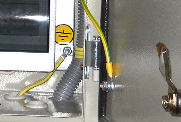
Second, the term main ground bus» defined in clause 20.5 GOST 30331.1(see and) as follows: "A busbar that is part of the grounding device of an electrical installation and is intended for the electrical connection of conductors to a grounding device." Connect to the main ground bus:
grounding conductor, through which the GZSH is connected to the ground electrode (see);
potential equalization conductors used in the building;
protective conductor, through which the protective busbar of the input-distribution device (ASU) is connected to the GZSH.
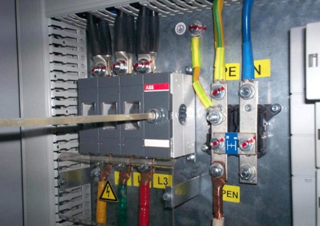
Thirdly, according to the requirements GOST R 50571.5.54(see) The PEN conductor should be connected to the PEN bus (clamp) or protective bus (clamp), which is usually installed in the ASU. On this bus (clamp), the PEN conductor is divided into protective and neutral conductors. The ASU protective bus is connected to the GZSH. Separation of the PEN conductor at the input terminal of the ASU, see.
Conclusion. The information on the separation of the PEN conductor set out in this article does not meet the requirements of GOST 30331.1 and GOST R 50571.5.54. Therefore, it misleads ordinary people who are trying to get correct information on FORUMHOUSE. Guided by such articles, it is impossible to create safe electrical installations of buildings.

Progress is moving forward with the times. They say that sometimes he is ahead of his time, and sometimes he is hopelessly behind. But if progress and time are not very material concepts, then technology is a very tangible and not very changeable thing. “Why these metaphysical arguments in an article about electrical networks?” - perhaps, you ask. But they are most directly related to the subject of discussion - how and, most importantly, why divide the PEN conductor into PE and N.
In 1913, in order to save metal and for some other reasons, the TN- C, that is, the neutral circuit in networks up to 1 kV, in which the zero working N and zero protective PE conductors are combined ( C ombined) into one common conductor PEN. Electrical safety in such systems is carried out by switching off the short circuit by fuses or automatic machines. In the USSR (and not only) with such a grounding system, a huge number of residential, public and industrial buildings. However, the obvious disadvantages of such a system - the danger of operating electrical installations in the event of a zero break or a ground fault - led to the need to create and use other grounding systems.
So, buildings have been built, potentially dangerous networks have been laid, and TNLA (for example, TKP 339-2011, clause 4.3.20) rightly regulate the use of more modern and safe grounding systems that allow the use of devices that increase electrical safety and reliability of power supply. Such a system is just TN- S, at which the protective and working zeros are separated ( S eparated) immediately at the substation. As a rule, such a system is used in new buildings. In such a network, it is possible to use residual current devices (RCDs), which is the main advantage over the TN-C system: an RCD or difavtomat protects a person from electric shock and electrical wiring from overloads.

Of course, it is not rational to carry out the reconstruction of each substation to create a TN-S system, but it is necessary to use safe and reliable systems. Here a compromise appeared - grounding according to the TN-C-S scheme, that is, the "arithmetic average" between the two systems mentioned above. Such a grounding system is used in the overhaul of buildings or the reconstruction of their networks. A four-core cable is connected from the substation to the building and in the building's input shield - the ASU (input switchgear) the PEN conductor is divided into PE and N, and the PEN conductor separation scheme is followed:
- PEN on the cable side are connected to the main ground bus (GZSH) PE, which is electrically connected to the cabinet or switchboard body.
- The GZSH is connected to the zero working bus N, mounted on insulators. These two tires are interconnected by a jumper of the same section as the tires themselves.
- PE conductors are connected to the PE bus, going to sockets and electrical receivers, to the N bus - working zeros of sockets and electrical receivers.
Often there are questions about the place of separation of the PEN conductor. Separation of the PEN-conductor is carried out before the input device to the building or country house, that is, to the introductory machine or knife switch. The N conductor coming from the N bus is connected to the electricity meter. Separately, I would like to note that after the separation of PEN in the direction from the energy source to the power receiver, the reconnection of PE and N is unacceptable, as is the use of fuses or circuit breakers in PEN, PE and N-conductors.

If you have a TN-C, TN-S system or combinations thereof recommended apply re-grounding (mainly consisting of natural grounding conductors) of PE- and PEN-conductors at the entrance to buildings. And, of course, no matter how perfect the grounding system is, if the resistance of the grounding device (GD) is not checked, there is no guarantee that this system will function properly. Resistance measurement can be carried out by specialists of our laboratory of electrophysical measurements.
Grounding is an integral part of the electrical network, of course, if this network is laid in accordance with regulatory documents. Such a grounding system as TN-C is no longer relevant, but due to the lack of the possibility of replacing it, it is operated both in multi-storey and in private houses. The main feature of the system is the division of the PEN conductor into a working zero and a protective one.
The main types of grounding systems
Before moving on to the PEN conductor, it is worth considering the classification in more detail. existing systems grounding and their brief description.
The need to separate the PEN conductor
Why do many users share PEN Explorer? The answer is simple, and it is spelled out in the electrical installation rules (PUE).
According to the PUE, when a voltage of 380/220 V is applied, a TN-S grounding system must be installed, in some cases TN-C-S is allowed. Unfortunately, the state of the wiring in high-rise buildings leaves much to be desired and TN-C is installed almost everywhere as grounding. Such outdated standards are unsafe under the loads of modern household appliances, and the protection of the electrical network is the main criterion for the safety of living in an apartment or a private house.
A prerequisite for the transition to more modern TN-S or TN-C-S is the division of the PEN conductor into PE and N. With this procedure, the PEN conductor is divided into working and protective zero. Many users try to do it themselves, so as not to attract people with the appropriate education, which will cause unnecessary spending. The consequence is incorrect installation, which leads to serious problems with the operation of the electrical network.
Separation of the PEN conductor
The PUE states: the place of separation of the PEN conductor must have appropriate distribution elements (tires). It is not allowed to cross the working and protective zeros. The main PEN conductor is connected to the place, which will later be mounted as a PE conductor.

This explanation is rather confusing, but the answer is quite simple: after the incoming PEN conductor is divided into PE and N conductors, it cannot be reconnected. The installation process is even simpler: just mount 2 busbars and connect them together with a jumper. In order to avoid errors during operation, tires should be marked. The zero working bus is marked with a standard in blue, and the corresponding designation is put on the ground bus.
The jumper can be either a wire with a cross section of at least 10 cm², or a plate made of the same material as the tires. In this case, an insulator must be installed between the bus of the working zero and the shield body. The ground bus can be attached directly to the shield.

After such installation, according to the PUE, the protective bus should be re-grounded. To do this, the rules suggest using natural grounding conductors. After carrying out the work, the resistance of the mounted grounding device should be checked and connected to the bus.
Is it possible to separate the PEN conductor in a common electrical panel
- The PE conductor must be re-earthed after separation. It is impossible to do this in a brush on the floor. Only in the main switchboard, where the introductory circuit breaker providing electricity to the whole house.
- It is forbidden to violate the layout of electrical elements adopted by certain authorities. Such an action, in the near future, will lead to a substantial fine. Therefore, the separation of the PEN conductor must be left to the relevant electrical service.
Now there is a gradual renovation of the electrical facilities in multi-storey buildings. This process is quite time-consuming and directly depends on the availability of funds. When replacing an old or installing a new electrical panel, the PEN conductor is divided into PE and N buses. In this case, all actions take place exclusively at the entrance to the house. Many organizations that perform this type of work do not deal with shields installed on each floor.
The sequence of separation of the PEN-conductor "from scratch"
In order to understand the correctness of this procedure, it is necessary to familiarize yourself with an example of its sequence. In the absence of appropriate education and admission to electrical work, it is not recommended to perform the process on your own.

It should be remembered that it is better not to perform the above procedure without knowledge and experience in the field of electrical or electrical engineering.
The most common mistakes when splitting a PEN conductor
When performing the separation of the PEN conductor yourself, you must strictly observe correct sequence this process. To achieve the most reliable contact of all connections, use high-quality electrical materials and have a reliable tool at hand that will save time.
The most common mistake is connecting the input zero to the bus, which will act as a ground. The PUE has a corresponding clause indicating that the input zero should be connected to the zero bus, and not to the protective one. Therefore, after work, you should pay attention to the connection and check everything again.

As a jumper, very often they use any material that comes to hand, not paying attention to its quality. Such an error will soon lead to a fire and the need to install a new electrical panel. You should not save on such important issues as electricity in a house or apartment.
Using poor quality electrical tape can also be dangerous. For short-term loads above the nominal values, such electrical tape may melt and the contact will remain open. Which is already a violation of electrical safety and increases the chances of a short circuit. For any electrical work, it is best to use heat shrink tubing.
When working with apartment shields, it is often found a large number of twists. This method of connection is already outdated, it gives poor-quality contact, which, like the use of aluminum with copper, can lead to a fire. Now there are special hydraulic presses, allowing you to connect wires using sleeves. The cost of such products is high, but the maximum quality of the connection is achieved. In the absence of such a tool, it is best to use bolted connections with several washers.
Ways to transition a multi-storey building to the TN-C-S system
It does not make sense to independently redo the TN-C system of the whole house, there are special services for this. Another question is when it will be the turn to overhaul the entire house.
Alteration options electrical system multi-storey building:
- No matter how trite, but many tenants of multi-storey buildings prefer to just wait. Now in the country, at the federal level, there are programs for capital repairs. The relevant authorities responsible for public Utilities, you can find out if the house is on the waiting list or not, and when the repair is scheduled.
- Can't wait overhaul, and pay for the services of a company that installs electrical networks. Certainly this method very costly, as the company is laying new lines, mounting grounding devices, installing new electrical panels. But in addition to electrical work, the company also takes on the regulatory framework, which it then independently certifies in all instances. Residents only need to pay for services.
- There is a collaboration option. Residents offer a lower amount, but will actively help with the work. Unfortunately, not many companies agree to this option, preferring to do everything on their own.

If none of the options listed above suit you, then you can independently separate the PEN conductor in the electrical panel in the stairwell. In this case, the expenses will be much less than when installing the introductory cabinet of the whole house. If you carry out the work yourself, but you only need to purchase Consumables, prices for which are now moderate.
Related videos
Content:
Electricity is known to be life threatening. But at the same time, protecting humans and animals from its deadly effects is quite simple. To do this, it is necessary to prevent the conditions for the occurrence of a current flowing through the body of a living organism. Most effective method for this - ensuring zero potential for all objects surrounding a person or animals in a dangerous place. This function is performed by grounding together with special conductors, which will be discussed in more detail below.
The basis for the design of safety systems against electric shock is the winding switching circuit electrical machine in a power plant or substation. Despite the fact that the source of electricity is an electric generator, it is separated from consumers by a whole power transmission system. It consists of a transformer, conductors and additional equipment. But since the power generator is three-phase, the entire subsequent power transmission network is also three-phase. But its configuration is set by the windings of the transformers.
For optimal use of the power of each phase, including the possibility of building single-phase power networks, the transformer windings are connected by a star. From the connection point of all three windings comes a conductor called neutral. There are electrical networks in which it is connected to a grounding device. In this case, a deafly grounded neutral is obtained. There are also networks in which there is no special connection to the grounding device. In this case, an isolated neutral is obtained.
But its isolation is conditional. There is a capacitance of the conductors relative to earth, as well as an equivalent resistance to earth of other elements of the electrical network. Therefore, an isolated neutral is characterized by resistance relative to earth with one or another value. When electrical equipment is connected to an electrical network with a voltage of up to 1000 V with one of two types of neutral, additional protective conductors are used:
- PE (from English words protective earth)
- grounding,
- potential equalization.
Also used are working conductors designed to pass load currents between consumers and neutral:
- zero neutral (N),
- combined zero protective working (PEN).
Designations on the diagrams
On the electrical diagrams grounding device is indicated as follows:

Currently, there are five ways to connect electrical equipment to a grounding device. Each of these systems has its own designation. All of them are shown below in the image:

The PE conductor in the image above is marked in yellow. At the same time in the system:
- TN-C conductor PE acts as a working conductor;
- TN-S PE conductor is made separately from the worker along its entire length;
- TN-C-S PE conductor, starting from an electric generator or transformer, partially plays the role of a worker up to a certain point.
The semantic load in the designations of grounding systems is carried by letters. The first of them - T and N - denote:
- T - equipment is grounded regardless of the type of neutral.
- N - solidly grounded neutral and equipment are connected.
- The following letters are:
- S - working and protective conductors are separated from each other as two separate wires.
- C - working and protective conductors are combined in one wire.
Since the beginning of the last century, the TN-C system has been widely used. Grounding was done on the side of the generator or transformer supplying the network. But if the working, and accordingly, it is also protective, PE wire was disconnected or separated for any reason, electric shock became a reality for the personnel. The more expensive TN-S system with a separate PE conductor does not have this drawback. In this case, it becomes possible to use switches based on differential protection for monitoring the currents of the working and PE wires. This provides power highest level security.
The TN-C-S option is, as it were, intermediate between the two systems discussed above. Before connecting to the busbars in the building, the PE wire acts as a working conductor. But further along all the premises, two wires are laid - PE protective and N working. However, in terms of reliability, this option is only slightly better than TN-C. If the PE wire (aka working, or PEN) burns out or is damaged between the building and the supply transformer (generator) on the consumer side of the building, phase voltage will appear on the PE wires. This is clearly shown below:

To prevent such emergencies the wire between the power source and the building must be additionally mechanically strengthened or additional grounds should be used, which, if broken, will replace those installed at the substation. At the same time, these groundings should be located no further than one hundred to two hundred meters from each other, depending on the frequency of thunderstorms observed in the area during the year. If their number is less than forty, a greater distance is chosen, more than a smaller one.
The shorter the length of the conductor that combines PE and PEN, the safer the electrical network.
Security requirements
For this reason, modern buildings use five wires (3 phases, PEN and PE) that start from the busbars located in the basement. They are laid further up to the last floor. In contrast to this scheme, in buildings old building PE branched off only in the floor electrical panel in houses with electric stoves.
- It is forbidden to use any pipes laid in the room as a PE conductor.
- If there are several grounding devices in the room, their potentials must be combined with an additional wire.

The PE conductor is used where it is impossible to obtain a properly performed grounding. This is typical for all multi-storey buildings. Therefore, the safety of people in these buildings directly depends on the correct connection of the PE wire. All information on how to properly make a PE conductor is set out in section 1.7 * PUE.


Mixed Personality Disorder: Causes, Symptoms, Types and Treatments
GTA 4 control settings
FAQ on Smuggling in GTA Online
LSPDFR - welcome to the police
The huge map of Grand Theft Auto San Andreas and its secrets