Connections and connections of grounding, protective conductors and conductors of the potential equalization and equalization system must be reliable and ensure the continuity of the electrical circuit. Connections of steel conductors are recommended to be made by welding. Allowed indoors and outdoors without aggressive environments connect grounding and neutral protective conductors in other ways that ensure the requirements of GOST 10434 "Contact electrical connections. General technical requirements" for the 2nd class of connections.
Connections must be protected from corrosion and mechanical damage.
For bolted connections, measures must be taken to prevent contact loosening.
1.7.140
Connections must be accessible for inspection and testing, with the exception of compounds filled with compound or sealed, as well as welded, soldered and crimped connections to heating elements in heating systems and their connections located in floors, walls, ceilings and in the ground.
1.7.141
When using devices for monitoring the continuity of the ground circuit, it is not allowed to connect their coils in series (in a cut) with protective conductors.
1.7.142
Connections of grounding and zero protective conductors and potential equalization conductors to open conductive parts must be made using bolted connections or welding.
Connections of equipment subject to frequent dismantling or installed on moving parts or parts subject to shock and vibration must be made using flexible conductors.
Connections of protective conductors of electrical wiring and overhead lines should be carried out by the same methods as the connections of phase conductors.
When using natural ground electrodes for grounding electrical installations and third-party conductive parts as protective conductors and potential equalization conductors, contact connections should be made using the methods provided for by GOST 12.1.030 "SSBT. Electrical safety. Protective grounding, grounding"
1.7.143
The places and methods of connecting grounding conductors to extended natural grounding conductors (for example, to pipelines) should be chosen so that when the grounding conductors are disconnected for repair work, the expected contact voltages and the calculated values of the resistance of the grounding device do not exceed safe values.
Shunting of water meters, valves, etc. should be carried out using a conductor of the appropriate cross section, depending on whether it is used as a protective conductor of a potential equalization system, a neutral protective conductor or a protective earth conductor.
1.7.144
The connection of each open conductive part of the electrical installation to the zero protective or protective earth conductor must be carried out using a separate branch. Sequential connection of open conductive parts into the protective conductor is not allowed.
The connection of conductive parts to the main potential equalization system must also be carried out using separate branches.
The connection of conductive parts to an additional potential equalization system can be performed using both separate branches and connection to one common permanent conductor.
1.7.145
It is not allowed to include switching devices in the circuit PE- and PEN- conductors, with the exception of cases of supplying electrical receivers with the help of plug connectors.
It is also allowed to simultaneously disconnect all conductors at the input to the electrical installations of individual residential, country and garden houses and similar objects powered by single-phase branches from overhead lines. At the same time, the division PEN- conductor on PE- and - conductors must be made before the introductory protective switching device.
1.7.146
If the protective conductors and/or potential equalization conductors can be disconnected using the same plug connector as the corresponding phase conductors, the socket and plug of the plug connector must have special protective contacts for connecting protective conductors or potential equalization conductors to them.
If the housing of the socket outlet is made of metal, it must be connected to the protective contact of this socket.
By the way, Dear experts, here is another comment on my original question, only from the ElectroAS website:
my question was like this -
How many conductors can be connected under one bolt?
Can you enlighten me on a question that is very difficult in my opinion: when in the construction of industrial enterprises and in residential construction, electricians connect 2 wires under one ground bolt, coming, for example, from two adjacent shields, are they right? I believe that they are wrong, because. in the PUE there is a requirement (1.7.119 - PUE 7th) for the main grounding bus - “The bus design must provide for the possibility of individually disconnecting the conductors connected to it. Disconnection must only be possible with the use of a tool." Does this mean that in general, absolutely everywhere and not only on the GZSH, ONLY one ground wire should be clamped under one bolt? This opinion or understanding breaks the work of one scientist - R.N.KARYAKIN Doctor of Engineering. Sci., professor of GROUNDING NETWORK STANDARDS, MOSCOW, Energoservice, 2002. There he writes as follows (by the way, he interprets GOST R 50571 (IEC364) as well): “10.5.4. It is forbidden to connect more than two cable tips. On the grounding (zero) bus, bolted connections of the required number of grounding, zero protective and zero working conductors must be provided.
10.5.5. It is not required to deliberately ground the cases of electrical equipment and apparatus installed on grounded metal structures, switchgear, switchboards, cabinets, shields, machine beds, machines and mechanisms, provided that reliable electrical contact with grounded bases is ensured. That is, the author states that no more than two tips can be put under the bolt. But he described this about shields, obviously for a bolt inside the shields, and not for wires with lugs that sit on the bolts of the ground loop, which usually runs nearby. GOST 10434-82 also states that it is allowed to put 2 ground wires under one bolt (Excerpt from GOST: (Changed edition, Rev. No. 1, 2).
2.1.12. It is recommended to connect no more than two conductors to each bolt (screw) of a flat terminal or to a pin terminal, unless otherwise specified in the standards or specifications on specific types of electrical devices.), but this GOST seems to be general technical and at the beginning of its text the following is written: “The requirements of the standard in terms of the permissible value electrical resistance and resistance of contact connections at through currents also apply to contact connections in circuits of grounding and protective conductors made of steel.
The standard does not apply to electrical contact connections of electrical devices for special purposes. Here the confusion of opinions and all as one documents bypass the exact indication - one or two wires (tip) must be put under one bolt. Why is it that in PUE 7 it is precisely about the GZSH that it is accurately described, but nothing exact is written about the rest of the grounding and, in particular, about my question that was voiced? Please help me figure out how to understand all this and come to any one correct understanding."
answer:
Message from FAQ
when in the construction of industrial enterprises and in residential construction, electricians connect 2 wires under one ground bolt, coming, for example, from two adjacent shields, are they right?
The ban applies to connecting more than two conductors, but up to two is always welcome. Although I personally think that it is necessary to tighten and prescribe - no more than one conductor.
Message from FAQ
I believe that they are wrong, because. in the PUE there is a requirement (1.7.119 - PUE 7th) for the main grounding bus - “The bus design must provide for the possibility of individually disconnecting the conductors connected to it.
And where did you find in paragraph 1.7.119 a ban on connecting 2 conductors? The connection of two lugs in the bolt does not lead to the impossibility of individual disconnection of the connected conductors. I unscrewed the nut, removed the corresponding tip and wrapped the nut back. What is the problem?
Message from FAQ
Does this mean that in general, absolutely everywhere and not only on the GZSH, ONLY one ground wire should be clamped under one bolt?
Where did you find the restrictions?
Message from FAQ
The standard does not apply to electrical contact connections of electrical devices for special purposes.
For a complete understanding, you need to familiarize yourself with the terms and definitions of the basic concepts.
GOST 18311-80
This standard establishes terms and definitions of concepts in the field of electrical products
Types of electrical products, electrical devices, electrical equipment
15. Electrical product (electrotechnical device, electrical equipment) general purpose- an electrical product (electrotechnical device, electrical equipment) that meets the totality technical requirements common to most applications.
16. An electrical product (electrotechnical device, electrical equipment) for special purposes - an electrical product (electrotechnical device, electrical equipment) made to meet the requirements specific to a particular purpose or for certain operating conditions and (or) having special performance characteristics and (or) a special design .
17. An electrical product (electrotechnical device, electrical equipment) of a specialized purpose - an electrical product (an electrical device, electrical equipment) of a special purpose, adapted for use with only one specific object.
Message from FAQ
Here the confusion of opinions and all as one documents bypass the exact indication - one or two wires (tip) must be put under one bolt.
On one bolt no more than 2 conductors (tips).
Message from FAQ
Why is it that in PUE 7 it is exactly about the GZSH that is accurately described, but nothing is written about the rest of the grounding and, in particular, about my question that was voiced?
You have confused the number of conductors with individual disconnection.
In general, comrade FAQ indicates that 2 conductors under the bolt are NOT FORBIDDEN !!! Well, about one conductor for one bolt on the GZSH - this only concerns the GZSH! Well, yes, most likely he is right ... and Volk is right !!! I hope our dialogue has now fully revealed the understanding of the topic raised by me! Let it become useful for all doubters))) I am also for tightening the requirements - one wire for one bolt! This is correct and easy to remember.
3.3. Protective earth requirements
3.3.1. An element for grounding should be equipped with products whose purpose does not require the implementation of a method of protecting a person from damage electric shock corresponding to classes II and III.
At the same time, it is allowed to perform without a grounding element and not to ground the following products:
intended for installation in inaccessible, without the use of special means, places (including - inside other products);
intended for installation only on grounded metal structures, if stable electrical contact of the contacting surfaces is ensured and the requirements of clause 3.3.7 are met;
parts of which cannot be under alternating voltage higher than 42 V and under direct voltage higher than 110 V;
grounding of which is not allowed by the principle of operation or the purpose of the product.
(Changed edition, Rev. No. 1, 3).
3.3.2. To connect the ground conductor, welded or threaded connections must be used.
By agreement with the consumer, the ground conductor can be connected to the product by soldering or crimping, performed by a special tool, fixture or machine.
3.3.3. Grounding clamps must comply with the requirements of GOST 21130-75.
It is not allowed to use for grounding bolts, screws, studs that act as fasteners.
3.2.2-3.3.3. (Revised edition, Rev. No. 1).
3.3.4. The bolt (screw, stud) for connecting the grounding conductor must be made of corrosion-resistant metal or coated with a metal that protects it from corrosion, and the contact part must not have a surface color.
(Revised edition, Rev. No. 4).
3.3.5. The bolt (screw, stud) for grounding must be placed on the product in a safe and convenient place for connecting the grounding conductor. Near the place where the grounding conductor is to be connected, provided for in clause 3.3.2, a grounding sign that is indelible during operation should be placed. The dimensions of the sign and the method of its implementation are in accordance with GOST 21130-75, and for lamps - in accordance with GOST 17677-82.
There must be a contact area around the bolt (screw, stud) for connecting the ground conductor. The platform must be protected from corrosion or made of anti-corrosion metal, and not have a surface color.
Measures must be taken against possible loosening of contacts between the grounding conductor and the bolt (screw, stud) for grounding (locknuts, spring washers).
The diameters of the bolt (screw, stud) and the contact area must be selected according to the current (see Table 1).
Table 1
Rated current of the electrotechnical Nominal thread diameter for the place Diameter of the contact area of the connection point, mm
products, A connection, not less than on the plane of the surface elevated relative to the surface
St. 4 to 6 M 3 10 7
"6" 16 M 3.5 11 8
"16" 40 M 4 12 9
"40" 63 M 5 14 11
"63" 100 M 6 16 12
"100" 250 M 8 20 17
"250" 630 M 10 25 21
"630 M 12 28 24
Notes:
1. For currents over 250 A, it is allowed to put two bolts instead of one, but with a total cross section not less than required.
When choosing the smallest bolt diameter for consumers and electromagnetic energy converters, the current value should be taken as the current. consumed by the product from the source (network), for sources of electromagnetic energy - the value of the rated load current.
2. For sources of electromagnetic energy having several rated currents, the choice of bolt diameter should be made according to the largest of these currents.
(Changed edition, Rev. No. 1, 3, 4).
3.3.6. If the dimensions of the product are small, and also if the grounding bolt (screw) is installed by welding its head, it is allowed to provide the necessary contact surface in connection with the grounding conductor using washers. The material of the washers must meet the same requirements as the material of the grounding bolt (screw, stud).
3.3.7. The product must be provided with an electrical connection of all metal non-current-carrying parts of the product that can be touched, which may be energized, with elements for grounding.
The resistance value between the grounding bolt (screw, stud) and each metal non-current-carrying part of the product accessible to touch, which may be energized, should not exceed 0.1 Ohm.
3.3.8. Elements for grounding must be equipped with the following metal non-current-carrying parts of products to be grounded:
shells, cases, cabinets;
frames, frames, clips, racks, chassis, bases, panels, plates and other parts of products that may become energized if the insulation is damaged.
It is allowed not to carry out elements for grounding in the following parts of the product (from among those listed above):
enclosures of products intended for installation on grounded shields, metal walls switchgear chambers, in cabinets;
non-current-carrying metal parts of the product that have electrical contact with grounded parts, subject to the requirements of clause 3.3.7;
parts fixed in or passing through insulating material and insulated from both earthed and live parts (provided that during operation of the product they cannot become live or come into contact with earthed parts).
3.3.9. Each part of the product equipped with an earthing element must be designed so that:
it was possible to independently connect it to the grounding conductor or grounding line by means of a separate branch, so that when removing any grounded part of the product (for example, for current repair- the earth circuits of other parts are not interrupted;
there was no need to connect several grounded parts of the product in series.
3.3.10. Grounding of parts of products installed on moving parts must be carried out by flexible conductors or sliding contacts.
3.3.11. If there is a metal shell, the element for its grounding must be located inside the shell.
It is allowed to execute it outside the shell, or to execute several elements both inside and outside the shell.
(Revised edition, Rev. No. 1).
3.3.12. Obtaining electrical contact between the removable and grounded (non-removable) parts of the shell should be carried out by directly pressing the removable part to the non-removable one; at the same time, at the points of contact, the surfaces of the removable and non-removable parts of the shell must be protected from corrosion and not covered with electrically insulating layers of varnish, paint or enamel.
It is allowed to electrically connect the removable part of the shell with the non-removable grounded part through the screws or bolts fastening it, provided that 1-2 screws or bolts have an anti-corrosion metal coating, and between the heads of these screws or bolts and the removable metal part of the shell there is no electrically insulating layer of varnish, paint, enamel, or toothed washers are installed between them that destroy the electrically insulating layer for electrical connection or without toothed washers, provided that the removable part is attached to a fixed grounded six or more bolts (or screws) and the absence of an electrical connection on removable parts of electrical devices.
It is also allowed to use toothed washers for electrical connection of the grounded shell and equipment mounted in the product, and install them for grounding the elements of the product through bolted connections.
(Revised edition, Rev. No. 3).
3.3.13. The requirements listed in clause 3.3 do not apply to products intended for operation only in areas with a tropical climate and made in accordance with GOST 15151-69, GOST 9.048-89.
To ensure the safety of people in networks up to 1000 V, zeroing is applied by neutral grounding. In these networks, grounding of equipment cases without a metallic connection to the neutral of a transformer or generator is prohibited. There should be no fuses and disconnecting devices in the neutral wire circuit used for grounding.
All equipment to be nulled is connected to the nulling line in parallel (see Fig. 1). Sequential zeroing is prohibited.
Grounding conductors are connected to the equipment by welding or by bolting. In all places where it is possible to connect temporary grounds for repair work, there must be special bolts or places cleaned and lubricated with petroleum jelly.
The zero terminal of the generator or transformer must be connected to the grounded neutral bus of the switchboard with a separate bus. The zero bus is attached to the shield frame on insulators. Substation switchboard frames are connected by busbars to the zeroing line.
Power panels and power distribution points are zeroed by connecting to the neutral wire of the supply line, and in the absence of such, a special ground bus must be laid from the substation. In addition, it is necessary to connect them to the shells of all cables, electrical wiring pipes and nearby grounded pipelines and metal structures.
Connection of zero and ground wires inside shields and cabinets is made to the ground bus using bolts. No more than two wires can be connected under one bolt.

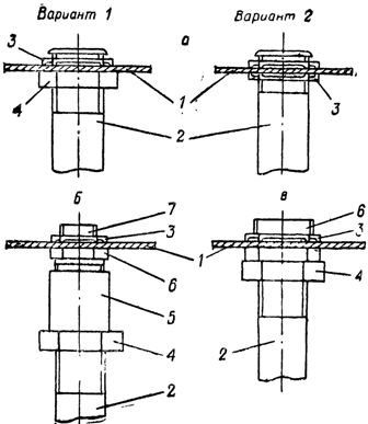
Rice. 1. Connection of parts of the electrical installation to the grounding network: a - electric motors, b - lamps
Electric motors and starting equipment are grounded using pipes in which power wires are laid, or using separate grounding conductors (Fig. 2). It is allowed, instead of zeroing individual devices or engines, to reliably ground the body of the machine on which they are installed.
Luminaire housings are zeroed by connecting to a neutral wire or a grounded structure. The grounding conductor must be connected with one end under the grounding bolt on the armature, and with the other end - to a grounded structure or neutral wire (Fig. 1).
Zeroing methods different types electrical equipment are shown in fig. 2-7.
Portable electrical receivers are grounded using separate copper conductors with a cross section of at least 1.5 mm2 in a common sheath with phase conductors.

Rice. 2. Zeroing of the engine housing: 1 - steel pipe of electrical wiring, 2 - flexible lead, 3 - jumper, 4 - contact flag 25x30X3 mm, 5 - ground bolt
Socket-outlets for portable current collectors must have an earthing contact, which is connected to the plug before the current-carrying contacts are connected.
Cases of mobile mechanisms that receive electricity from stationary sources or mobile power plants must have a metal connection with grounding or grounding of these power sources.
Rice. 3. Connection of a metal case with a steel pipe of electrical wiring: a - the diameter of the hole in the case corresponds to the diameter of the pipe, b - the diameter of the hole in the case is less than the diameter of the pipe, c - the diameter of the hole in the case is greater than the outer diameter of the pipe, 1 - metal case, 2 - steel pipe electrical wiring, 3 - adjusting nut K480-K486, 4 - locknut, 5 - straight coupling, 6 - futorka, 7 - double nipple.
Cases of single-phase welding transformers are neutralized by using the third core in a three-core supply hose cable.
Metal sheaths of wires and cables, armor, flexible metal sleeves, steel pipes electrical wiring must be grounded.

Rice. 4. Zeroing of single cable structures: a - painted, welded to embedded elements, b - galvanized, fixed with brackets, 1 - embedded element, 2 - cable structure, 3 - bracket, 4 - conductor attached at the beginning and end of the route to the zeroing line, welded to each mortgage element or bracket.
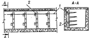
Rice. 5. Grounding of cable structures in the channels: 1 - the grounding conductor is welded to each embedded element and is connected to the grounding line at the beginning and end of the route, 2 - the embedded element
Note. With a double-sided arrangement of cable structures, the grounding conductors at the beginning and end of the route are connected by jumpers by welding

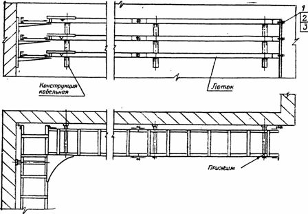
Rice. 6. Zeroing of welded trays laid along the wall: 1 - M6x26 bolt, 2 - M8 nut, 3 - washer
Rice. 7. Zeroing of the carrier cable: a - for a flexible current supply, b - for hanging a cable or cable wires, 1 - carrier cable, 2 - cable with an insulating sheath, 3 - sleeve Note. A carrier cable connected at both ends to the grounding line by welding or a sleeve.
The sheath and armor of the cables are zeroed at both ends of the connection paths with a jumper made of a flexible stranded copper conductor, the cross section of which is indicated below.
Metal poles and reinforcement of reinforced concrete poles are connected to a zero grounded wire.
in residential and public buildings be sure to zero the metal cases of household stationary electric stoves, boilers and portable electrical appliances with a power of more than 1.3 kW, as well as metal cases of electrical equipment and metal pipes electrical wiring located in basements, undergrounds, stairwells, public restrooms, showers, etc. premises.
In rooms without increased danger, as well as in kitchens, zeroing is stationary installed equipment(with the exception of electric stoves), as well as portable electrical appliances with a power of up to 1.3 kW (irons, stoves, kettles, vacuum cleaners, washing and sewing machines etc.) is not required.
In bathrooms of residential and public buildings, in baths, medical institutions, etc., metal cases of bathtubs and shower trays must be connected with metal conductors to water pipes for potential equalization (Fig. 8). It is forbidden to use gas pipelines for potential equalization.
Rice. 8. Grounding the metal body of the bath by connecting to the water pipes: 1 - water pipe, 2 - grounding conductor, 3 - clamp, 4 - washer, 5 - washer, spring cut, 5 - bolt, 7 - nut, 8 - tip, 9 - screw, 10 - bath body, 11 - screw.
In public buildings, premises with increased danger and especially dangerous ( industrial premises catering establishments, boiler houses, cold rooms, production shops of consumer services enterprises, school workshops, bathrooms, ventilation chambers, air conditioning chambers, machine rooms of elevators, pumping stations, heat points, etc.) all stationary and portable electrical receivers that do not have double insulation, steel pipes for electrical wiring, metal cases of shields and cabinets must be zeroed. 220 and 380 V socket outlets for connecting portable and mobile electrical receivers must have protective contacts connected to the neutral wire.
In rooms without increased danger, having dropped ceilings, lamps and metal constructions ceilings must be zeroed.
In entertainment enterprises, metal structures and cases of all stage apparatuses, as well as cases of all shields in all rooms, are subject to grounding.
The metal cases of projectors and sound-producing equipment must be grounded with separate insulated wires and additionally connected to a separate ground located near the control room.


Chicken in kefir - recipes for marinated, stewed and baked poultry for every taste!
Simple Chicken Recipe in English (Fried) Recipes in English with translation
Chicken hearts with potatoes: cooking recipes How to cook delicious chicken hearts with potatoes
Recipes for dough and fillings for jellied pies with mushrooms
Stuffed eggplant with chicken and mushrooms baked in the oven with cheese crust Cooking eggplant stuffed with chicken