17
A guide to creating a CNC milling CNC machine. Chapter 1 Machine Electronics
Good day to all! And here I am with a new part of my story about CNC - machine tool. When I started writing the article, I did not even think that it would turn out to be so voluminous. When I wrote about the electronics of the machine, I looked and got scared - the A4 sheet was written on both sides, and there was still a lot to tell.
Now that you're on the most serious hobbyist budgets, you can go into your garage or shop and craft that little piece you need for your latest project. With advanced technology, how could you do that? Well, believe it or not, it's not the mill itself that has advanced to allow it.
What the hell are you talking about? No corrosion like other metal models, no water or other damage with some other wooden models. With such a small footprint and weighing around 50 pounds, it's incredible useful tool, which will easily fit on your desktop or can be moved from location to location in your store.
In the end it turned out like this manual for creating a CNC machine, working machine, from scratch. There will be three parts of the article about one machine: 1-electronic stuffing, 2-mechanics of the machine, 3-all the subtleties of setting up the electronics, the machine itself, and the machine control program.
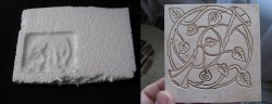
In general, I will try to combine in one material everything useful and necessary for every beginner in this interesting business, what I myself read on various Internet resources and passed through myself. By the way, in that article I forgot to show photos of crafts made. I'm fixing this. Styrofoam bear and plywood plant.
Now this is a solid investment. "After a customer buys our product, if there is a manufacturing defect, we will help them replace the parts." Most people who want to get into building such a project will also want to build their own computer, since a very minimal system is required.
To give you a quick look, the basic steps. While he wants to master the capabilities of the machine and understand what it can do. On the Swiss type, the part is fed through the guide bush. Thus, the stationary tool cuts the part as it exits the spindle.
Foreword
After I assembled my little machine without significant expenditure of effort, time and money, I was seriously interested in this topic. I looked on YouTube, if not all, then almost all the videos related to amateur machines. Particularly impressive were the photographs of products that people make on their “ Home CNC". I looked and decided - I will assemble my big machine! So, on a wave of emotions, I didn’t think it over well, I plunged into a new and unknown world for myself CNC.Didn't know where to start. First of all, I ordered a normal stepper motor Vexta 12 kg/cm, among other things with the proud inscription "made in Japan".
The first machines were automatic cam automatics. The shop is still quoting new jobs on these machines. Their mechanical turn-on is fast, but they require high production volumes because the set-up time is so long.
Choice of design features
He says that new users are often surprised by the ability of these machines to produce a finished production part quickly. This year, expected spending is more evenly distributed across the various industry applications. The application in this case is related to protection. Swiss machining provides cost-effective effective method manufacture of dust collector tips and firing pins used in military rifles.

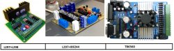
While he was driving through all of Russia, he sat in the evenings at various CNC forums and tried to make a choice STEP/DIR controller and stepper motor drivers. I considered three options: on a microcircuit L298, on field workers, or buy ready-made Chinese TB6560 about which there were very conflicting reviews.
Box tool turned accurate diameter. However, when a customer asked to be able to order parts in smaller quantities and with shorter lead times, the store had to start moving inventory to accommodate the request. Stockpiling led to additional costs, so Mr. Groth had to find cost compensation.
The Swiss lathe is a variety of lathe that feeds stock through a guide bushing. The machine feeds work from the spindle and passes the tool. His company was a screw machine. When he bought it from his previous owner, the machines that came with him were cam-controlled automatic lathes for the precise production of small parts. Grotto, a gunsmith, had no experience with this type of machine, so he taught himself how to use them.
For some, it worked without problems for a long time, for others it burned out at the slightest user error. Someone even wrote that he burned out when he slightly turned the shaft of the motor connected at that time to the controller. Probably the fact of the unreliability of the Chinese and played in favor of choosing a scheme L297+ actively discussed on the forum. The scheme is probably really unkillable. the field drivers of the driver by amperes are several times higher than what needs to be fed to the motors. Even if you need to solder yourself (this is only a plus), and the cost of the parts came out a little more than the Chinese controller, but it is reliable, which is more important.
I'll digress a little from the topic. When all this was done, I didn’t even have the thought that someday I would write about it. Therefore, there are no photos of the assembly process of mechanics and electronics, only a few photos taken on a mobile phone camera. Everything else I clicked specifically for the article, already assembled.
The case of the soldering iron is afraid
I'll start with the power supply. I planned to make an impulse, I fiddled with it for probably a week, but I could not defeat the excitement, which came from nowhere. I wind the trance at 12v - everything is OK, I wind it at 30 - a complete mess. I came to the conclusion that some kind of bullshit climbs on feedback from 30th to TL494 and tear down her tower. So I abandoned this impulse, since there were several TS-180s, one of which went to serve the motherland as a power trance. And whatever you say, a piece of iron and copper will be more reliable than a bunch of crumbling. The transformer rewound to the required voltages, but it was necessary + 30V to power the motors, + 15V to power IR2104, +5v on L297, and a fan. You can apply 10 or 70 to the motors, the main thing is not to exceed the current, but if you do less, the maximum speed and power decrease, but the transformer no longer allowed it. I needed 6-7A. Stabilized voltages 5 and 15v, left 30 “floating” at the discretion of our power grid.
The case of the soldering iron is afraid
He himself and with his own hands learned to create these machines and use them effectively, even effectively. Now the latest of these machines is Swiss. For the sake of training the machine and improving its skills, mr. Finding and confirming the time it takes to move will allow him to use the car more efficiently in the future. At least that was his experience getting to know these cam machines when his shop was new.
Once again, in the Swiss style, Mr. Groth teaches himself to use the machine efficiently. Douglas Paoletta knows something about this learning curve. Machinists and programmers moving from one to the other must adjust their thinking about the mechanical cycle in different ways. He makes the following distinctions.
All this time, every night I sat at the computer and read, read, read. Setting up the controller, choosing programs: which one to draw, which one to operate the machine, how to make mechanics, etc. etc. In general, the more I read, the more terrible it became, and more and more often the question arose “what for do I need this ?!”. But it was too late to retreat, the engine was on the table, the details were somewhere along the way - we must continue.
It's time to solder the board. Available on the Internet did not suit me for three reasons:
1 - The store that ordered the parts was not there IR2104 in DIP packages, and they sent me 8-SOICN. They are soldered to the board on the other side, upside down, and accordingly it was necessary to mirror the tracks, and them ( IR2104) 12 pieces.
This change affects the nature of programming offsets. He says: On the usual lathe stock falls out of the cartridge on specified length. Increasing the turning length or drilling depth entails a "minus" offset on a conventional lathe, but requires a "plus" offset on a Swiss type. The order of the cuts in the cycle also changes with the Swiss type.
“Because of the length of the guide bushing, we have to segment the part into sections, or the rod stock will fall out of the guide bushing when we remove the stock,” he says. This segmentation usually means machining parts in 750 inch sections, length of standard guide bushing area.
2 - Resistors and capacitors were also taken in SMD packages to reduce the number of holes that needed to be drilled.
3 - The radiator I had was smaller and the extreme transistors were out of its area. It was necessary to shift the field workers on one board to the right, and on the other to the left, so I made two types of board.
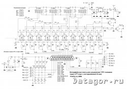
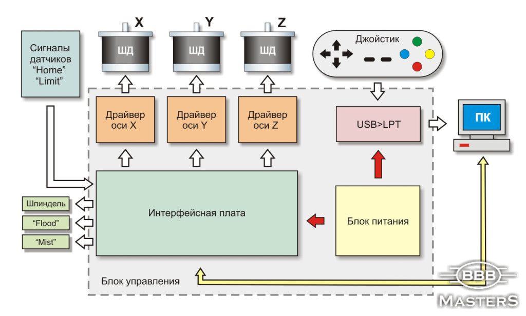
Machine controller diagram

For the safety of the LPT port, the controller and the computer are connected via an optocoupler board. I took the scheme and the signet from one well-known site, but again I had to redo it a bit for myself and remove unnecessary details.
The guide sleeve is the heart of the Swiss machine. Using a guide bush, which is wrong size to work, will lead to concentricity errors. Most Swiss machines use oil as the cutting fluid, not water. Benefits include freedom from the growth of odor-causing bacteria, as well as hands like prunes, which are exposed to water-based coolant all day as a result. However, the main drawback is in this very word "refrigerant".
Compared to water, oil is less efficient at dissipating heat. Sewing machine cutting quickly gets hot inside the work area, so changing tools may require gloves or shop towels, Mr. Paoletta said. Reasonable equipment of the machine with a fire extinguishing system.
One side of the board is powered via the USB port, the other, connected to the controller, is powered by a + 5V source. Signals are transmitted via optocouplers. I will write all the details about setting up the controller and decoupling in the third chapter, but here I will only mention the main points. This decoupling board is designed for safe connection of the controller stepper motor to the LPT port of the computer. Completely electrically isolates the computer port from the machine electronics, and allows you to control a 4-axis CNC machine. If the machine has only three axes, as in our case, unnecessary parts can be left hanging in the air, or not soldered at all. It is possible to connect end sensors, a forced stop button, a spindle enable relay and another device, such as a vacuum cleaner.
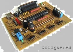
It was a photo of the optocoupler board taken from the Internet, and this is what my garden looks like after installation in the case. Two boards and a bunch of wires. But there seems to be no interference, and everything works without errors.
Paoletta says he loves to see the shift in thinking that happens when a new Swiss-style user completes a piece in a single cycle that previously required multiple operations or even multiple machines. The Swiss type will probably have 7 to 13 axles. Seeing how much work can be done quickly in the small working area of a machine can surprise store staff who are using this type of machine for the first time.
Make all necessary holes
Grotto was amazed and his car didn't even have one. a large number axes. He controls the screw pins on a Swiss machine that rotates only one by one. However, he was accustomed to turning parts carefully when he ran them on a more conventional lathe. If he cuts too aggressively, the thin parts will deviate enough to leave tool marks on the workpiece. In comparison, the much greater stability that the Swiss type brings to the cut means it no longer needs to be delicate.
The first controller board is ready, I checked everything and tested it step by step, as in the instructions. I set a small current as a trimmer (this is possible due to the presence of PWM), and connected the power (motors) through a chain of 12 + 24v bulbs so that it was “nothing if nothing”. I have field workers without a radiator.
The engine hissed. The good news is that the PWM is working as it should. I press a key and it spins! I forgot to mention that this controller is designed to control a bipolar stepper motor i.e. one with 4 wires. Played with step / half step modes, current. In half-step mode, the engine behaves more stable and develops high speeds + accuracy increases. So I left the jumper in the "half step". With the maximum safe current for the engine at a voltage of about 30V, it turned out to spin the engine up to 2500 rpm! My first machine without PWM never dreamed of such a thing.))
As a result, the efficiency of screw screws doubled. But at the same time, the size of the party is small. Although not directly comparable to the Swiss type, its screw machines are also effective for precision machining of small parts. Indeed, he still cites new jobs for them. However, these machines are inefficient for the small production volumes his customers are increasingly demanding because their setup times are too long.
However, the next Swiss type he buys will be different. The current one is selected for a particular family of parts; it accommodates a maximum rod size of 12mm. The possibility of using hand wheels should be used. The spindle drive is also unchanged.
The next two motors ordered more powerful, Nema at 18kg/s, but already “made in China”.
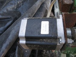
They are inferior in quality Vexta After all, China and Japan are two different things. When you rotate the shaft with your hand, the Japanese do it somehow softly, but the Chinese have a different feeling, but so far this has not affected work. There are no comments for them.
I soldered the remaining two boards, checked through the "LED stepper motor simulator", everything seems to be fine. I connect one motor - it works fine, but not 2500 rpm, but about 3000! According to the already worked out scheme, I connect the third motor to the third board, spins for a couple of seconds and got up ... I look at the oscilloscope - there are no pulses on one output. I call the fee - one of IR2104 pierced.
Relatively strong motors are difficult to turn over with hand wheels due to translation. For all who no longer know the lost art of scraping, here is the explanation. Before precision milling, planing and grinding machines, there was a need for flat metal surfaces in the emerging engineering industry. Machine parts were made by casting or forging, partly by rolling, but neither process could produce sufficiently flat surfaces. The procedure used was as follows: on an already existing, only cleaned plate, the so-called veneer paint, a greasy fabric, traditionally blue, was applied.
Well, maybe I got a defective one, I read that this often happens with this mikruha. I solder a new one (I took 2 pieces with a margin), the same nonsense - it turns STOP for a couple of seconds! Here I strained myself, and let's check the field workers. By the way, my board has IRF530(100V / 17A) vs. (50V / 49A), as in the original. A maximum of 3A will go to the motor, so a reserve of 14A will be more than enough, but the difference in price is almost 2 times in favor of the 530s.
So, I check the field workers and what I see ... I didn’t solder one leg! And all 30V from the field worker flew to the output of this "irka". I soldered the leg, carefully examined everything again, put another one IR2104, I'm worried myself - this is the last one. I turned it on and was very happy when the engine did not stop after two seconds of operation. Modes left as follows: engine Vexta- 1.5A, engine NEMA 2.5A. With this current, revolutions of about 2000 are achieved, but it is better to limit them programmatically in order to avoid skipping steps, and the temperature of the motors during prolonged operation does not exceed the safe for motors. The power transformer copes without problems, because usually only 2 motors are spinning at the same time, but additional air cooling is desirable for the radiator.
The surface to be treated was then placed on this plate, moved in a circular manner and removed again. On the high surfaces of the surface, the color remained sticky, then they were blue. Using a scraper, the worker then scraped off the marked high spots. This process was repeated until the entire surface was evenly covered with blue spots and therefore even. The cross change of the scraper creates a characteristic pattern. The small depressions that inevitably remain on the surface serve as oil pockets and improve lubrication.
Now about the installation of field workers on the radiator, and there are 24 of them, if anyone has not noticed. In this version of the board, they are located lying down, i.e. the radiator just lays down on them and is attracted by something.
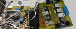
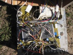
Of course, it is desirable to put a solid piece of mica to isolate the heatsink from the transistors, but I did not have one. Found a way out. Because in half of the transistors, the case goes to plus power; they can be mounted without insulation, just on thermal paste. And under the rest, I put pieces of mica left over from Soviet transistors. I drilled the radiator and the board in three places through and through and tightened it with bolts. I got one large board by soldering three separate boards around the edges, while soldering around the perimeter for strength copper wire 1mm. All electronic stuffing and placed the power supply on some kind of iron chassis, I don’t even know from what.
I cut out the side and top cover from plywood, and put a fan on top.
The attentive reader wonders where the first flat spotted plate came from. You end up with three flat plates instead of one. So there is nothing wrong with cockroaches, on the contrary. However, the person who put his hand on this car was having a bad day.
On the plain language this means that the guide surfaces of the table only cool down in these places, which is definitely not enough and leads to rapid wear. Also note the drilled thread for one of the spindle nut mounting screws that easily displace Fresh air.
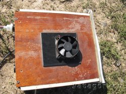
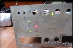
I drilled holes in the front panel for numerous LEDs for indicating operating modes.
For quickly connecting / disconnecting engines and the control unit, I used connectors from the last millennium. And the contact is good and the desired current is kept without any consequences for themselves.
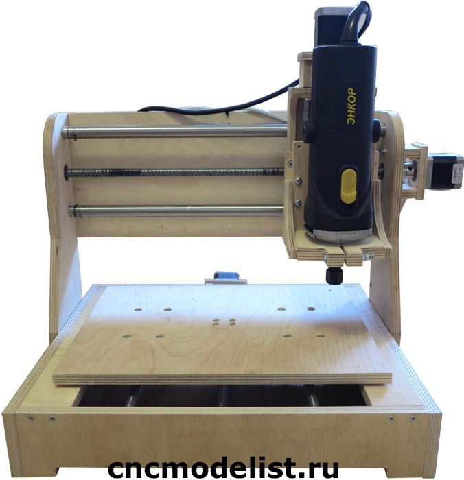
Milling machine CNC machine can be a great helper in small manufacturing or home repair. The cost of factory CNC milling machines (cnc) is quite high, so some craftsmen successfully create them with their own hands according to unique drawings.
Now, he was not the same height at all points, as the following pictures show. Here we have a difference of almost a tenth of a millimeter between the right and the left. The wedge bars for setting up the leadership game were no better. Also the insides of the swallows on the saddle didn't look promising, as shown in the following picture.
Here is an interesting picture of the leadership of the table. Why the relatively roughly corrugated surface was still provided with a crowbar decorative pattern eludes my knowledge. If the surface was cut fine then it would make sense because it created pockets. But this is completely redundant.
Making a homemade cnc machine with your own hands is not easy, sometimes it takes several months.
Machine design
The bed for a homemade metal milling machine is easiest to make from a square pipe 80 x 80 mm, quite low. The low height makes the device quite stable and prevents vibration. The stand for fixing the rails is also made of rectangular metal pipe 60 x 20 mm. The bed is bolted, as welded joints deform the structure. Bolted fasteners allow you to set the device exactly on the level, the contact area is large, the fastening is reliable and fairly rigid, without backlash.
My first thought, of course, was to complain about the car. But that would mean assembling the car, wrapping it up, yelling at the dealer, and canceling the whole process. This man came and fixed everything. Here are his gifted hands. Now everything is fine and nothing fluctuates. German cockroaches are much more complex and time consuming, unless it is just a decoration and affection of Zltaschen. Chinese workers are also worth money, and more often if you believe the papers.
By the way, if you want to see where all the fancy cars come from, you should look here: the resemblance is, of course, pure coincidence, and you can imagine the colors quite differently. A visitor to my site pointed me to another manufacturer in China, where everything is again.
Working area size homemade machine must be made from 32 x 35 cm. The length of the guide shafts along Y and X is 1.6 cm, along Z - 1 cm.
Guides are best made profile, otherwise they will sag along the X axis.
Plain bearings are better to choose industrial, albeit the most inexpensive. Their use will reduce the likelihood of backlash.
The Z axis is mounted on a screw gear, as it is quite heavy. To transmit torsion to the lead screw from the Z-axis, a toothed belt with a width of 10 mm is used. Such a scheme allows you to reduce the beating and facilitate the placement of the stepper motor relative to the travel screw. Reduces machine weight and saves vertical space.
The axle itself is made from an aluminum plate, and two stepper motors are installed behind it. Their purpose is to transfer torsion to the Z-axis screw by means of a toothed belt, another motor transmits movement along the X-axis with a belt. The Z-axis lead screw can be made from a construction stud.
If instead of a belt a screw gear is made in the drawing, the speed will increase to 850 rpm and the accuracy of the homemade cnc machine tool. But this design is much more expensive.
If you plan to water-cool the spindle, you should also provide a water pump, as well as a set of rubber tubes.
Engine and software
For a homemade CNC milling machine (they are also called cnc), a stepper motor with a torque of 18 kg / cm is suitable. Such a motor is sufficient for a spindle with a power of 1.5 kilowatts. It will be possible to process parts from soft metals and simple work on carbon steel.
The controller, frequency convector and motherboard can be installed in a single protective box. Although many are afraid of interference, they are quite rare. Such a control center is prone to overheating in hot weather!
CNC milling machines, assembled by hand according to drawings, work under the guidance of Linux. Some drivers will have to be written by hand, for example, for a stepper motor with microstepping. Controllers with USB output do not work under Linux, this should be taken into account when choosing them. You need to buy a four-axis controller and make the appropriate settings.
Ready set for machine assembly
Most craftsmen who assemble the machine with their own hands are faced with the need to purchase many finished parts. As a result, the price homemade device may be higher than factory. The process of self-assembly is very lengthy, and the result is often disappointing. Often, craftsmen remake several times machines assembled without drawings and calculations, bringing their work to the desired standard.
There is a possibility in one working day with the help of wrench and screwdrivers to make a CNC router with your own hands using a ready-made kit - a kind of simple constructor for adults, containing absolutely all the details and drawings. The set is a guarantee of the high quality of the future machine.
The device and testing of a homemade milling cutter:


How to cook ham in the oven at home
Pain in the lower abdomen during pregnancy, reasons for what to do Can the lower abdomen hurt if pregnant
Protein for muscle gain
The best vitamins for men according to customer reviews
How to lose weight on a vegan diet?