At the exhibition "Metalworking-2017" held in Moscow, the premiere of the "Rapier SGS-01" machine took place. Thanks to its appearance, the production of barrels for small arms can rise by new level
The eighteenth international exhibition "Metalworking-2017" has opened in Moscow, at the Expocentre on Krasnaya Presnya. She will work from 15 to 19 May. One of the real sensations of the exhibition is the demonstration of the machine deep drilling, the likes of which we have never released.
In total, on an area of 39.5 thousand square meters 1000 companies from 30 countries demonstrate their achievements. Despite the sanctions, machine tools are offered to Russian enterprises by such countries as Austria, Great Britain, Germany, the USA, France, Switzerland, Sweden and Japan.
Minister of Industry and Trade Denis Manturov noted: "The exhibition is a key event in the field of material processing technology and makes a significant contribution to the implementation of relevant government programs and investment projects. It presents the best examples technological equipment meeting all the requirements of international standards".
It is gratifying that, along with the world's leading machine tool companies, Russian companies are also represented. True, I must say that they mainly produce licensed machines adapted to our conditions.
But the USSR was one of the world leaders in the field of machine tool building, no matter how strange it may seem to someone today. Back in 1991, our country ranked second in the world in terms of consumption of machine tools and third in terms of their production - after the USA and Japan. At the same time, the "soviet" machines were not much inferior in quality to foreign models. And for the production of machine tools with numerical program management we even took the lead. And a real rout Russian machine tool industry in the 1990s was hardly accidental.
In the early 2000s, attempts were made to revive this branch of engineering. Billions of rubles were allocated. They were simply stolen. The investigation was led by the FSB. Some of the culprits were found and jailed. But the machine tool industry has not really revived in our country. Today, all the most modern Russian factories, including defense ones, are equipped either with imported machines or manufactured in our country under license.
That is why it is possible to call the premiere demonstration of the machine "Rapier SGS-01" sensational. SGS-01 is a single-spindle deep drilling machine. Single-spindle, in turn, indicates that one workpiece can be processed at a time. However, as the developers assure, if necessary, it can be made with two or even three-spindle.
But perhaps the most surprising thing is that it was designed and assembled not by machine tool specialists, but by the creators of small arms.
The initiator was the head of the Central Design and Research Bureau of Sports and Hunting Weapons (TsKIB SOO), located in Tula, Alexei Sorokin. This bureau, of course, deals with both sports and hunting weapons, but its main direction is combat.
Here is what Alexey Sorokin told the correspondent " Russian newspaper about why we need a deep drilling machine and how it was created.
The machine is my private project, without false modesty, but also without pathos, says the director of TsKIB SOO. - On the one hand, its creation is not connected with the main activity - the management of a defense enterprise. On the other hand, I see all the problems of machine tool building and I understand perfectly well that good weapons can only be produced on good machines.
In particular, in order to manufacture the barrel of an assault rifle, machine gun or hunting rifle, equipment is needed that allows for the so-called deep drilling. It is not produced in Russia, and imported is very expensive, and it is problematic to purchase it today. Western manufacturers are reluctant to sell machine tools to defense enterprises.
Deep drilling is characterized by the ratio of the diameter of the drilled hole to the depth of drilling. If this ratio is 1 to 10, then it is already deep, for example, a hole with a diameter of 7.62 mm to a depth of 76 mm is deep. But in gun barrels, the ratio can be 1 to 100 or even more, and this requires special technology.
Neither in the USSR, nor in Russia, CNC deep drilling machines for small calibers have ever been produced. So we were first. And we tried to set maximum requirements during its design, which would ensure its effective use in a wide variety of technological operations.
For example, this is a wide range of possibilities for the rotation of the workpiece, counter-rotation of the drill, control of temperatures, forces, and so on. In the production of the machine, we have achieved a unique geometry. The accuracy of the coincidence of all elements along the drilling axis is less than a micron, and the error of the bed is 4.7 meters less than a hundredth of a mm, such an accuracy of the machine will give hole accuracy, high purity and minimal center-to-center drift. We can drill blanks from any of the strongest steel up to 1300 mm long. The maximum caliber is 30 mm.
Our development, by the way, has the widest possible applications. After all, deep drilling is used not only in weapons production. This includes medical equipment, energy, and the tool industry (production of channels in molds), and transport engineering, and even the manufacture of special tools for forestry - there are also technologies that require deep drilling of small diameter holes.
For a complete technological cycle of manufacturing gun barrels a line of nine different machines is needed. We clearly imagine what these machines should be and, most importantly, how they should be made. If we find understanding, then I am sure that the production of machine gun barrels, machine guns, sniper and hunting weapons in our country will rise to a qualitatively new level. That is why participation in the Metalworking-2017 exhibition is very important for us.
We were able to implement a real import-substituting project. Most the best machines deep drilling is produced in Germany. But they are very expensive, and in terms of their characteristics they are in no way superior to our machine, which we show at this exhibition.
Necessary business. I watched on ORSIS how the barrels were turned. The coin on the edge on the moving bed does not move. But there are imported, and here is ours!
Deep hole drilling machines are presented in two main layouts - horizontal and vertical. They are generally used for boring holes as well, and differ significantly from other types of machines designed for processing long workpieces. Machine tools occupy large areas, are designed (for drilling holes in a wide range of diameters), as a rule, in a horizontal design and have a length that is at least twice the length of the workpieces for which they are designed. Usually, the beds of such machines are designed as composite, joined. This ensures the convenience of their manufacture and delivery to the consumer.
A special system for supplying cutting fluid (coolant) to the cutting zone, for transporting chips from the cutting zone, lubricating and cooling drills occupies a large place in the design of machine tools. This system includes a pumping unit, devices for supplying coolant to the part and further to the cutting zone, a chip removal system, a chip collector, drain tanks with settling tanks, magnetic and other traps (filters) of solid particles from the coolant and coolant cooling devices. In addition, machines must have protective covers to protect against splashing and leakage of coolant.
Almost all models can be used for deep rough and fine boring (reaming), i.e. performing operations for processing smooth cylindrical and (if available) special devices) conical holes.
In case of failure due to the high technological specificity of the processing process, it is very difficult to replace them with other machines. Therefore, when planning production, given that deep drilling is one of the initial operations technological process, you should always have a reserve of equipment, not only in terms of loading, but also in terms of the number of machines.
Machines for deep drilling and boring,
especially machines designed for high-speed processing, must meet the following requirements:
Convenient and quick installation (alignment, fixing) and removal of workpieces;
Required range of spindle speeds and feed limits (machining modes) with clear stepless control systems, especially providing stepless feed rate control on the go and its clear indication;
Continuous and reliable removal of the generated chips (slurry consisting of coolant and chips);
Coolant filtration and cooling;
Continuous monitoring of the process by automatically operating protective and control devices;
If possible, have an automated control system for the entire processing process, in particular, a system numerical control machine and processing.
Receiving devices sufficient in terms of cubic capacity for collecting and separating the formed chips from the coolant;
Fast adjusting movements and especially reliable fastening (if necessary) of the working bodies of the machine (front racks and stem stocks, calipers, lunettes, etc.);
Reliable protection of operating personnel and workshop area from coolant splashing;
Meet the increased requirements of fire safety and industrial sanitation.
Specific for machines that produce deep drilling and boring is their increased energy consumption compared to many other machines. In some cases, up to 30% (and sometimes more) of the energy consumed only for the cutting process during drilling is consumed only for chip removal.
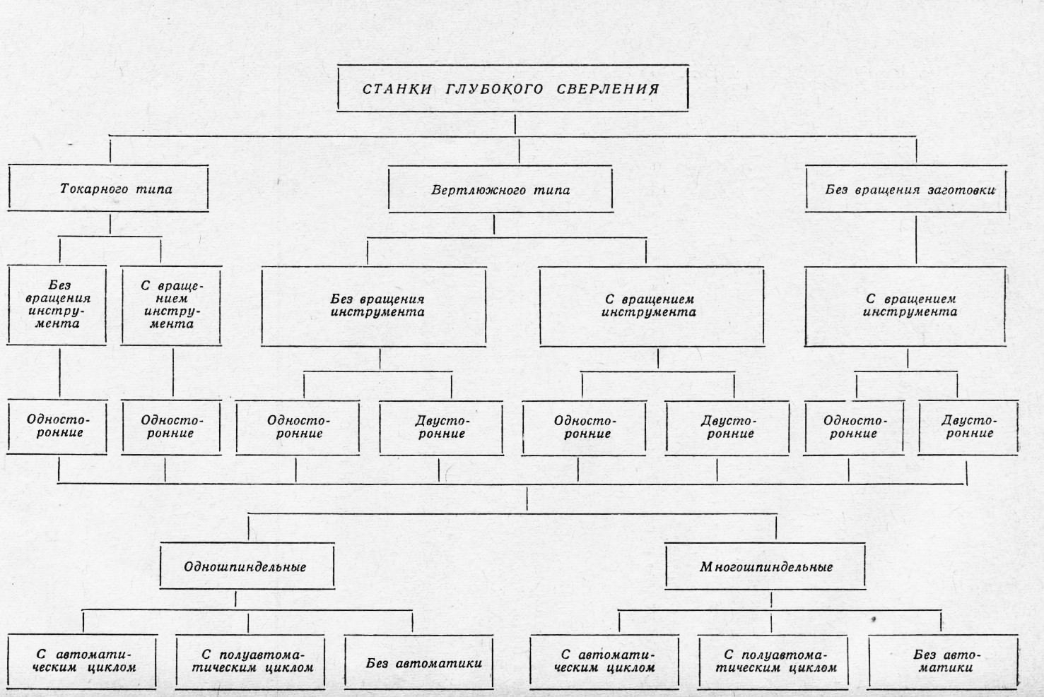
All deep drilling machines,
despite some diversity , can be divided into the following groups: turning type; swivel type; without rotation of the workpiece when drilling. Each of these types of machines is designed to process a certain type of workpiece.
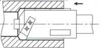
For lathes
(rice. one) grandma 10 similar to the headstock lathe. Hollow spindle (sometimes solid) designed for fast rotation of the workpiece 2 ; the cross section of the spindle is relatively small. The workpiece to be machined is installed with the output end in the chuck 11 , fixed at the working end of the spindle, and the input end is supported either by an oil receiver 8 , if machining is carried out with internal chip removal, or steady rest with external chip removal. Long workpieces are additionally supported by steady rests during machining 1 . Stem 3 with a drill is fixed either on the caliper flock or in the stem stock 5 . The stem head has a chip collector 6 , the chips from which enter the receiving chute and then to the chip collector. Stem rests are located between the stem stock (caliper) and the workpiece (oil receiver) for long drilling lengths 4 (racks) supporting the stem.
Lathe-type machines can also be produced with a stem rotation spindle device, which is installed on the stem headstock and (if necessary) gives the stem, and, consequently, the tool rotation.
In lathe-type machines, as a rule, workpieces pre-machined along the top are drilled, which in their shape represent bodies of rotation of small transverse dimensions.
Small parts with deep holes in mass and large-scale production are processed both on two and multi-spindle machines, and on machines with a vertical design. These machines are also usually referred to as a group of lathes.
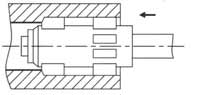
In swivel type machines ( rice. 2) workpiece 2 mounted partially inside a hollow spindle, called a swivel, placed in a rack 10 . The swivel spindle in some cases is equipped with two chucks for fixing the workpiece in two zones along the length.
() the workpiece to be processed is installed partially inside a hollow spindle, called a swivel, placed in a rack. The swivel spindle in some cases is equipped with two chucks for fixing the workpiece in two zones along the length.
Swivel Versus Spindle drilling machine turning type has large transverse dimensions. Therefore, the design of the swivel is not designed for rapid rotation of the workpiece during drilling. The second end of the workpiece can be (if necessary) installed in the swivel rest 1 .
On the bed 9 placed front rack 7 with an oil receiver, the sleeve of which is tightly connected to the conical end of the workpiece. When the machine is working, the rack 7 rigidly fixed to the frame. From the pumping system, coolant is supplied to the oil receiver and further along the gap between the drilled hole and outer surface the stem is fed to the drill (into the cutting zone).
Stem 3 fixed in the feed carriage 5 having a stem rotation drive. A steady rest can be used to support the stem. 4 .
The carriage has a chip catcher 6 , into which coolant with chips enters through the stem hole from the cutting zone.
The cutting speed when drilling on machines operating with simultaneous rotation of the workpiece and tool should be determined in accordance with the speeds of rotation of both the stem and the workpiece.
Typically, swivel-type machines process workpieces that are undesirable or impossible to rotate quickly. These are forgings, rolled products and other parts that differ in their shape somewhat from bodies of revolution, and parts that have a significant imbalance. Heavy parts such as rotors and rolls with large diameters of the middle feet, having holes of small diameters, it is advisable to process on swivel-type machines using counter-fast rotation of the stem with a drill.
When drilling workpieces with a large relative length of holes in large-scale and mass production, it is advisable to use machines that provide double-sided deep drilling (a kind of swivel-type machines).
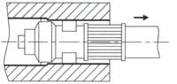
Deep drilling machines without workpiece rotation
(rice. 3) are much less common than the first two types of machine tools. They are used for drilling parts that require drilling. deep holes without rotating the workpiece and for drilling several parallel deep holes. Such machines come in two varieties:
with a stem headstock that performs longitudinal movements;
with a table for fixing the workpiece, having longitudinal movements.
The first type is more commonly used. In this case, a machine with a non-rotating workpiece, when drilling, resembles a modular machine with a self-acting power head. On such a machine, the workpiece 2 fixed on the table 1 placed on the bed 9 . To the end of the workpiece before drilling by moving the front rack 7 pressed by its bushing oil receiver 8, connected by a hose to the pumping system. Stem 3 , supported by a steady rest 4, fixed in the feed carriage 5 having a stem rotation drive. As in the considered schemes, a chip collector is located at the end of the carriage 6 .
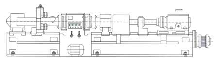
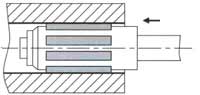
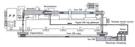
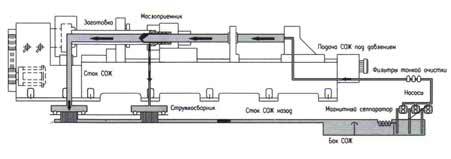
As an example of the units and assemblies that make up the machine, it is shown (with a certain convention) on rice. 4. In real version, the machine can be used for drilling workpieces up to 6000 mm long and with an outer diameter of 80…400 mm. On the machine it is possible to produce: continuous drilling of holes? from 8 to 80 mm, hole drilling? up to 320 mm, boring holes? up to 320 mm and hole punching? up to 320 mm. The machine has two - three section cast bed with a length of 22,000 mm. The spindle head is fixed to the left on the upper part of the bed 2 with a special chuck - a pot. Workpiece rotation 3 , fixed in the headstock chuck and the oil receiver guide sleeve, is carried out from the engine 1 DC power 40 kW. The angular speed of rotation of the spindle is infinitely adjustable from 40 to 1000 min 1 . Naturally, when installing long workpieces on the machine, steady rests are used to support them.
The machine is equipped with a massive oil receiver for supplying coolant to the cutting zone with internal chip removal (STS technology (BTA)). Naturally, the machine must have a set of oil receivers for drilling holes of various diameters.
The oil receiver is installed in the front pillar 4 , which, when installing the part, presses the oil receiver to the end of the workpiece and is attached to the machine bed. On the rack there is a push-button control panel and instrumentation that allows you to control the operation of the machine, the electrician of which is located in the electrical cabinet 14 .
The machine is equipped with a feed carriage 6 , in which the ST stem is attached. When drilling, the stem is supported by a stem rest 5 . The carriage has working and accelerated movements from the feed box 7 . The feeds also change steplessly (from 5 to 3000 mm/min), and the rapid movements of the carriage (with stem and drill) are made at a speed of 5000 mm/min.
The carriage is designed to install either a stalk-holder or a special high-speed stalk headstock with a stalk rotation drive with adjustable spindle speed up to 2000 min 1 . This allows the machine to carry out the process of deep drilling with counter-rotation of the tool, which is necessary when drilling holes of small diameter in large workpieces.
(It should be noted that in a number of machine designs, the carriage and the feed box are combined into one unit - the tool feed carriage, which provides both the tool feed and, if necessary, its rotation).
To the rear end of the stem holder bracket located in the carriage 6 , attached peculiar knee 10 for removal to the chip collector 9 liquids and chips. Having a grid on top, a chip collector 9 separates large chips from liquid.
Chip collector 9 moves along the guides of the tank - tank 8 for coolant, which is located at the rear of the frame and is located below the floor level. The coolant tank on machines can be large capacity and contain up to 6...8 m 3 coolant, which contributes to the process of natural cooling of the coolant after its passage through its cycle. It is considered mandatory to have a coolant tank capacity of at least ten times the maximum drilling coolant flow per minute. So, for example, if the maximum possible flow rate when drilling on the machine is 300 l / min, then the capacity of the coolant tank should be at least 3 m 3.
The machine must be equipped with a collector - a sump 12 , into which contaminated coolant enters from the chip collector tank. Coolant is cooled in the sump collector, finally cleaned of small particles various filters, including magnetic separators, and merges through the pipeline into the main tank.
The machine has a powerful hydraulic system 13 (shown conditionally), consisting of pumps with drives, safety valves and control devices. In the real version, the coolant pumps are located as submersible in the coolant tank area, which makes the machine much more compact. In a number of designs, coolant cleaning systems are also installed in the tank area.
During the operation of the machine, the coolant from the pumps is supplied to the oil receiver with the appropriate pressure and the required flow rate. When using a machine for processing holes in a wide range of diameters, the pump system must be able to supply coolant with pressures up to 10 MPa and at flow rates up to 300 l/min.
Deep hole lathe simplified design ( rice. 5) allows you to perform deep drilling and boring without rotating the tool. Typically, machines of this type have a center height of no more than 300 mm and allow drilling holes with a diameter of up to 40 ... 50 mm in parts up to 3000 mm long.
On the headstock spindle 12 fixed cartridge - pot 13 with radial windows. Through these windows, after drilling or boring, you can disconnect the tool from the stem so as not to remove the tool through the machined hole in reverse.
Part to be installed 1 the cone of the front part is pre-centered in the oil receiver bushing 5 , then it is verified (along the neck A on the part) in the cartridge - pot 13 (by moving the cams) and is mounted in a cartridge - a pot 13 his fists. oil receiver 5 installed in the front guide post 6 . By moving the rack, the oil receiver is brought to the part to fix it and create tight contact between the guide sleeve of the oil receiver and the cone of the part when the part is installed. And then to the neck 4 details are brought in steady rest cams 3 .
Stem 7 with drill 2 fixed in the carriage 8 , the movement of which is carried out from the lead screw coming from the headstock.
When the machine is running coolant from the pump 11 is fed through the hose to the oil receiver 5 and further along the gap between the stem and the hole into the cutting zone. Further, through the hole in the stem, the coolant with chips enters the chip collector 9 , where chips are separated from the coolant and drained into the tank 10 . Systems for more thorough cleaning of the coolant from solid inclusions can be placed in the tank. As a rule, in machines of this type, the entire pumping system, including the coolant tank and pumps, is located below the floor level. Since it is possible to drill holes of small diameter on the given machine, the pumping system must ensure the supply of coolant with a pressure of at least 10 MPa at flow rates up to 100 l/min.
Gun drilling machines
built according to general scheme, although their general layout can be horizontal, vertical, inclined and different types- turning or by the type of drilling of a fixed workpiece. In this case, various motion patterns are possible: a stationary workpiece - a rotating drill, a rotating workpiece - a non-rotating drill, and counter-rotation of the workpiece and drill. Naturally, the feed is most often attached to the tool.
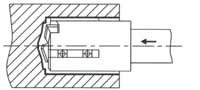
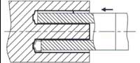
In the above diagram ( rice. 6, a) blank 1 fixed between two bushings 10 . A guide bushing is pressed to the outer end of the workpiece 9 fixed in a special holder 8 . The sleeve provides the initial direction of the drill 2 when cutting it. Stem 3 drill shank 4 fixed in the spindle 5 located in the feed carriage. When drilling, the carriage is given feed, and the drill is given rotation. Sleeves can be used to support the stem in the system. 6 located in the rests and in the front rack. Sealing ring 7 located in the holder 11 front post, prevents the exit of coolant with chips beyond the chip collector in the front post.
Gun drilling scheme ( rice. 6b) provides for the supply of coolant into the hole of the stem, and the removal of chips from the outside - along the groove of the stem.
Ejector drilling
(see RITM, 2009, No. 9, p. 1114), as a rule, is used on universal machines. A diagram of a possible adjustment of a lathe for ejector drilling (DTS technology) is shown in rice. 7.
On the caliper 7 machine tool is placed 5 to secure the workpiece 6 . In the same device, a conductor sleeve is also placed. 4 . ejector tool 3 fixed in the spindle chuck 1 lathe, providing coolant supply to a rotating tool and chip removal into a chip collector. When drilling, the tool receives rotation from the machine spindle, and the workpiece is fed along with the caliper. The pump station and coolant hoses are not shown in the diagram. When modernizing and adjusting the machine, it is necessary to place a conductor bushing 4 in fixture 5 in the direction of its axis so that between the end of the workpiece 6 and the bushing had a gap of no more than 1 mm. With the specified values of the gap and the length of the sleeve, favorable conditions are provided for the circulation of the coolant and the ejection effect.
It is also important to ensure the alignment of the hole in bushing and holes in the chuck for the outer tube of the tool.
Depending on the drilling diameter pumping station must supply coolant with certain parameters.
By degree of automation
deep hole drilling machines can be mainly divided into three groups;
machines with an automatic cycle of work;
machines with partial automation of the processing or process control;
machines without automation devices.
Currently, the second group of machines is most widely used. This group includes machine tools with automatic operating safety devices, mainly for protection against overload, overheating of the liquid, for cleaning the liquid from solids and cooling the liquid, etc.
Production of machines for deep drilling
and delivering them to Russian market both domestic enterprises and foreign firms are involved.
LLC "Ryazan machine-tool plant"
- the main domestic manufacturer of machines for deep drilling and boring. All machine models meet high level by constructive equipment and by the level of automation of elements of control processes. Machines are available in several design forms:
turning, swivel, body.
Depending on the model, the machines can carry out deep drilling using STS technology (BTA), ELB technology (gun drilling), ejector drilling (DTS technology) and drilling with a single-tube tool with internal coolant supply. Machine tools are presented for processing parts in a fairly large range of lengths and diameters of machined holes.
JSC "Melitopol machine-tool plant named after. October 23"
(Ukraine ) . Machine tools are presented that work according to the gun drilling scheme: single-spindle semi-automatic mod. GS750, GS1100, GS3500; single spindle semi-automatic mod. MG53GV.700; duplex semi-automatic mod. 2GV600. Drilling diameter up to 10 mm, drilling depth up to 600 mm. The maximum diameter of the installed workpiece is 250 mm.
Company Vnesh Komplekt
(Ukraine) presents a deep drilling machine model 2GV - 600. Drilling is carried out with gun drills with a diameter of 7 to 10 mm with a maximum drilling depth of 600 mm (
Deep drilling - view machining metals by cutting holes with a rotating tool. Deep drilling - the depth of the hole must be more than 10 cm, or a dimension deeper than 5 original diameters (5 * d).
There are several methods of deep drilling:
- STS Method (Single Shaft Drilling) - This method is best suited for machining parts in high-volume or mass production. The complexity of the process lies in the fact that it is required to use an oil receiver with numerous supply hoses, while the workpiece rotates. The single rod system is considered the most efficient for producing high quality holes;
- Ejector drilling (Ejector) - ejector technology of deep drilling, which is used to obtain holes with a diameter of 18 to 180 mm (up to 250 mm - when reaming). Lubricating fluid is supplied to the space between outer pipe and an inner pipe (two-pipe method - DTS, Double Tube System). The coolant enters from the outside of the drilling head, washes it and is discharged together with the chips into inner tube. The ejector method is suitable for making holes d=20-60 mm. and up to 1200 mm deep, not excluding intermittent holes.
- Drilling system with gun or tube-blade drills with internal cutting fluid (ELB) - This method is suitable for small enterprises where the technology requires to obtain deep holes of small diameter. Recommended dov. = 35-40 mm., up to 50 * d. At this method there is no need to carry out such operations as reaming and reaming.
Deep drilling machines find their application in a wide range of industries, including: defense industry, automotive industry, oil and gas industry, energy, production of hydraulic cylinders, heavy engineering.
Deep drilling machines are used in almost any mechanical engineering: in the production of cars and tractors, river and sea vessels, in instrument making.
Most deep hole parts are made from castings, bending and subsequent welding into pipes, rolling, etc., i.e. more productive technologies.
Lathe type deep hole drilling machine Swivel type deep hole drilling machine Multi-spindle deep hole drilling machine
Deep hole drilling equipment
Strict specific requirements are imposed on this group of equipment:
- they must be able to quickly change and install workpieces;
- chip removal must be carried out without stopping;
- must have an effective ability to cool and clean the coolant;
- must be safe for personnel.
Deep drilling machines are divided into several types, which we will consider below.
Classification of deep hole drilling machines
The first type is turning. They allow processing bodies of revolution previously processed on other equipment. By design headstock are similar to classic lathes.
The workpiece is fixed in a chuck mounted on a spindle, which gives it rapid rotation. The opposite end of the part is installed in the steady rest (centering support), if the chips are removed from the outside, supported by an oil receiver - special device, designed to supply coolant to the cutting zone, and also perform a number of functions if internal chip removal occurs. The stem with the drill is installed in the stem stock or caliper post. In terms of compactness, they are inferior only to swivel-type machines.
The disadvantage is the lack of the possibility of simultaneous double-sided drilling.
On swivel-type machines, one end of the workpiece is fixed inside a hollow spindle with low rotation speeds. In swivel machines, the workpiece and the cutting tool simultaneously rotate. They take up the least space in the shop, i.e. are compact. In terms of electricity consumption, they occupy an average position relative to lathes and machines without rotation of the workpiece.
Swivel - a hollow spindle with large transverse dimensions.
The main nodes are similar to the nodes of lathes. In some models, the spindle has 2 chucks for installing parts.
Machines of this type are used for drilling deep holes in workpieces that are sensitive to high speeds: those with eccentricity - the axis of the hole is offset relative to the main axis, as well as parts that are unbalanced or heavy.
It is advisable to use double-sided drilling only in the production a large number details, i.e. massively, with very long holes without imposing high requirements on hole accuracy, drilling difficult-to-machine materials or two coaxial blind holes.
The disadvantage of the method is the need for the simultaneous presence of right and left drills.
To process two or more parallel holes, machines are used without rotating workpieces. Drilling can be carried out by a stem head, which moves relative to a fixed workpiece, or the part is installed on a table that has the ability to move longitudinally. In terms of electricity consumption, the machines are the most economical. The disadvantage of this type of equipment is the poor quality of drilling.
According to the degree of automation, machines can be classified into three groups:
- automatic machines;
- semi-automatic - are the most common;
- manual.
Deep drilling process and methods
Deep drilling is used only when it is necessary to obtain a hole of a certain accuracy and quality, and this method will be the best in terms of performance.
When drilling deep holes, the main problem arises - the removal of chips and cutting fluid, therefore, a constant removal of chips is forced by supplying coolant or compressed air under pressure.
Deep drilling can be done in two ways:
- solid - a hollow hole is drilled into the part (traditional drilling);
- annular - a part of the material is drilled into the part in the form of a ring so that a rod remains inside. If the hole is through, then the rod is separated from the part, if it is deaf, the rod is removed by special methods.
This method is used when it is necessary to machine holes longer than 80 drill diameters.
If you find an error, please highlight a piece of text and click Ctrl+Enter.
To ensure high quality and productivity in deep hole machining, a modern, high-performance and reliable special machine is required.
Machine tools for processing deep holes manufactured by Ryazan Machine Tool Plant meet these requirements.
Based on a variety of practical tasks, have been developed special machines various standard sizes and in various designs.
The following forms may apply:
Structural form No. 1 (lathe machine):
Locating a rotating product in the headstock chuck and roller rests. The stem with the installed tool is attached to the stem stock. Hole machining is done with a non-rotating tool.

Structural form No. 2 (Lathe machine):
Locating a rotating product in the headstock chuck and roller rests. Depending on technological needs, processing can be carried out with a rotating product with both a non-rotating and a rotating tool.

Structural form No. 3 (Swivel machine):
Locating a rotating product in the headstock chucks and roller rests. End faces of hollow preparations are easily accessible for measurements, tool change; work by the "draw boring" method. Machining takes place with a non-rotating tool.
Structural form No. 4 (Swivel machine):
Locating a rotating product in the headstock chucks and roller rests. Processing can be performed with a rotating product as a non-rotating and rotating tool.

Structural form No. 5 (Machine of case execution): Basing a non-rotating product in fixtures. Hole machining is done with a rotating tool.
Efficient processing methods to achieve high quality.
Machining deep holes with high precision and surface quality is considered a difficult technological operation. Special processing methods are used that meet the high requirements for processing quality and can significantly reduce technological time.
Processing methods:
Drilling in solid material: It differs in that all drilled material is removed in the form of chips. Drilling diameter 40 ... 125 mm. |
|
Hole drilling: |
|
Boring: |
|
Pull boring: |
|
Rolling: |
|
High-quality drilling is only possible with continuous chip removal from the cutting area. In addition, cutting temperature has a significant effect on tool life. Both factors require a high performance coolant unit with a large tank and a powerful pump unit.
When drilling, the machine operates with an external coolant supply and internal chip removal, coolant is supplied between the boring bar and the workpiece wall to the tool blade. The removal of the mixture from the coolant and chips is carried out through the internal cavity of the rod. Thus, contact between the machined surface and the chips is eliminated, which contributes to obtaining a better surface:
When boring, the method with external chip removal is widely used, for which a hole in the workpiece obtained in previous operations is used. The coolant, together with the chips, is discharged into the chip collector. Through the chip receiver, the coolant returns to the common reservoir and thus the cycle ends:
A written application for the purchase of a machine can be left on the website in the section
Buy machines for deep drilling and boring, boring machines production of the Ryazan Machine-Tool Plant is possible only from the official representatives of the RSZ. Contact information on the pages:
All groups of machines RSZ


How to understand: will the kitten be fluffy?
What kind of light alcohol can be drunk for pregnant women: the consequences of drinking
Why do the legs swell in the ankles and ankles of the feet in pregnant women: causes and methods of treatment
The wedding of Prince Harry and Meghan Markle: scandalous and secret details of the marriage (photo) The future marriage of Prince Harry year NTV
How to close white plums for the winter