Plasma spraying (or, in other words, diffusion metallization) effective method changes in physical and mechanical properties, as well as the structure of the main surface. Therefore, it is often used for decorative purposes and to increase the durability of the final product.
The principle of plasma spraying
Like traditional methods of surface coatings, during diffusion metallization, a layer of another metal or alloy is deposited on the metal surface, which has the properties necessary for the subsequent use of the part - desired color, anti-corrosion resistance, hardness. The differences are as follows:
- High-temperature (5000 - 6000 °C) plasma significantly speeds up the coating process, which can be fractions of a second.
- During diffusion metallization in a plasma jet, chemical elements from the gas where the treatment is carried out can also diffuse into the surface layers of the metal. Thus, by adjusting the chemical composition of the gas, it is possible to achieve a combined surface saturation of the metal with atoms of the required elements.
- The uniformity of temperature and pressure inside the plasma jet ensures high quality of the final coatings, which is very difficult to achieve with traditional metallization methods.
- Plasma spraying is characterized by an extremely short process time. As a result, not only productivity increases, but also overheating, oxidation, and other undesirable surface phenomena are eliminated.
Working installations for the implementation of the process
Since most often an electric discharge is used to initiate high-temperature plasma - arc, spark or pulse - the equipment used for this method of deposition includes:
- Discharge generation source: high-frequency generator or welding converter;
- A working sealed chamber where the workpiece to be metallized is placed;
- A reservoir for gas, in the atmosphere of which high-temperature plasma will be formed;
- A pumping or vacuum unit that provides the necessary pressure for pumping the working medium or for creating the required vacuum;
- Process control systems.
The operation of a plasma torch that performs plasma spraying occurs as follows. A sprayed part is fixed in a sealed chamber, after which an electric discharge is excited between the surfaces of the working electrode (which includes the sprayed elements) and the workpiece. At the same time, a liquid or gaseous medium is pumped through the working zone with the required pressure. Its purpose is to compress the discharge zone, thereby increasing the volumetric density of its thermal power. Highly concentrated plasma provides dimensional evaporation of the electrode metal and at the same time initiates pyrolysis of the medium surrounding the workpiece. As a result, a layer of the desired chemical composition is formed on the surface. By changing the characteristics of the discharge - current, voltage, pressure - it is possible to control the thickness, as well as the structure of the deposited coating.
The process of diffusion metallization in vacuum occurs similarly, except that the plasma compression occurs due to the pressure difference inside and outside its column.
Technological equipment, consumables
The choice of electrode material depends on the purpose of the deposition and the type of metal being processed. For example, for hardening stamps, the most effective electrodes are made of iron-nickel alloys, which are additionally alloyed with elements such as chromium, boron, and silicon. Chromium increases the wear resistance of the coating, boron - hardness, and silicon - the density of the finish coating.
When metallizing for decorative purposes, the main criterion for choosing the metal of the working electrode is the configuration of the sprayed surface, as well as its appearance. Copper sputtering, for example, is carried out with M1 electrotechnical copper electrodes.
An important structural component of the process is the composition of the medium. For example, if it is necessary to obtain highly resistant nitrides and carbides in the sprayed layer, organic media containing carbon or nitrogen must be present in the gas.
Post-treatment of the finished coating
Due to the nature of the process, the density of the sprayed layer and the strength of its adhesion to the base metal are not always sufficient to ensure the durability of the coating. Therefore, often after processing, the part is subjected to subsequent surface melting using an oxy-acetylene flame, or in thermal furnaces. As a result, the coating density increases several times. After that, the products are ground and polished using a carbide tool.
Taking into account the subsequent finishing of the product, the thickness of the metal layer after processing is taken to be at least 0.8 - 0.9 mm.
To give the part the final strength properties, it is quenched and tempered using the technological regimes recommended for the base metal.
Plasma spraying increases heat resistance, wear resistance and hardness of products, increases their ability to resist corrosion processes, and spraying for decorative purposes significantly improves the appearance of parts.
The limitations of diffusion technology plasma spraying the excessive complexity of the workpiece configuration as well as the relative complexity of the installations used are considered.
With low requirements for the uniformity of the resulting layer, you can use more simple installations, structurally reminiscent of welding semiautomatic devices. In this case, plasma spraying is carried out in an air bubble, which is formed when the compressor blows the treatment zone. The electrodes, which include the sprayed metal, move sequentially along the contour of the product. To improve the adhesion of the sprayed metal with the base, a filler material is also introduced into the spraying zone.
If you find an error, please select a piece of text and press Ctrl + Enter.
17.1. Classification of types of thermal spraying.
Thermal spraying is a coating process based on heating the material to a liquid state and spraying it onto the product - the substrate using a gas jet.
Coatings are applied without a significant increase in the temperature of the substrate, which eliminates the appearance of deformation of the sprayed parts.
Thermal spraying can be divided into two groups (Fig. 17.1.):
1) flame;
2) gas-electric.
Rice. 17. 1. Classification of types of thermal spraying.
1) The essence of flame spraying is to melt the sprayed materials with a gas flame and spray them with compressed air (Fig. 13.2.)
Powder, solid wire and flux-cored wire or rods are used as the sprayed material. As a combustible gas, acetylene, propane-butane, natural gas, etc. are used. The disadvantages of gas-flame spraying are the low quality of coatings due to the low flame temperature, low particle transfer rates and a high content of oxides in the coating.
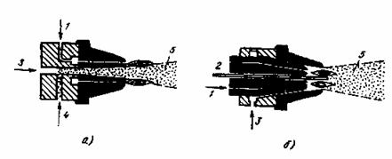
Figure 17.2. Scheme of spraying with a gas flame:
1 - combustible mixture; 2 - sprayed wire; 3 - compressed air;
4 - sprayed powder; 5 - metallization torch.
2) The essence of electrometallization spraying is to melt the wire with an electric arc and spray the liquid metal with compressed air. Spraying with compressed air leads to significant burnout of the components and their oxidation.
Electrometallizers are much easier to manage than flame ones. In electric arc spraying, wire is used as the starting material.
High-frequency metallizers, like electric arc, are wire-type devices. The heating of the wire is carried out by inducing high-frequency currents in it. HDTV lamp generators (70-500 kHz) are used as a power source. The performance of high-frequency metallizers is 1.5-2.5 times higher than the performance of electrometallization ones. The disadvantages of this method of deposition are the low efficiency of installations (15-20%), the relatively low adhesion strength of the deposited layer to the substrate.
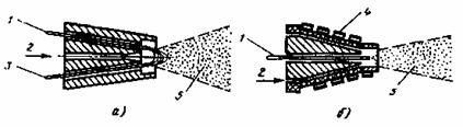
Rice. 17.3. Scheme of electrometallization spraying:
a - electric arc, b - high-frequency: 1.3 - sprayed wire; 2 - compressed air; 4 - inductor; 5 - metallization torch.
17.2. The essence of plasma spraying.
One of the high-performance coating methods that uses low-temperature plasma is plasma spraying.
The physical concept of “plasma” was introduced in 1923 . Langmer to designate the gaseous state, in which gases become conductive due to the ionization of atoms. During plasma spraying, electrons, ions, and neutral particles occur in the jet. To ionize the plasma, an electric arc is used, and in order to increase the temperature, the arc is compressed, which sharply increases its temperature. The temperature of argon plasma reaches 20000-23000 C. Plasma spraying is widely used in those branches of mechanical engineering where it is necessary to protect machine parts from intense wear by applying various resistant alloys, increase the performance of wear parts several times, protect parts from corrosion, erosion, cavitation, abrasive wear, thermal shocks, etc. The thickness of the deposited layers varies from 0.03mm up to several millimeters.
Sprayed coatings have the following advantages: high density; strong adhesion to the base material; smooth surface spraying, which does not require subsequent machining (grinding); relatively low consumption of sprayed material compared to other methods.
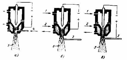
Figure 17.4. Plasma spraying schemes.
a - supply of the sprayed material into the plasma jet through the nozzle; b - the same behind the nozzle section; c - plasma metallization with a dependent arc wire; 1 - gas input; 2 - water input; 3 - electrode wire; 4 - powder supply; 5 - metallization torch.
Metallization with wire is carried out by an independent or dependent arc.
Argon, nitrogen, ammonia, helium and argon-hydrogen mixtures are used as plasma-forming gases. The best gas to protect the tungsten electrode is the inert gas argon.
The sprayed materials are made in the form of powder or wire. The advantages of plasma spraying with powder materials (compared to wire materials) are as follows: more uniform (without post-treatment) and finer coating structure; the possibility of obtaining combined coatings and so-called pseudo-alloys by mixing powders from various materials; low cost.
For plasma spraying, spherical powders with a granulation of 5-100 microns are most suitable.
17.3. Equipment for plasma spraying.
The installation is designed for spraying coatings using a plasma jet. The installation kit includes the following components: a DC power supply (complete with a rectifier or converter), a control cabinet, a plasma torch, a feeder for dosing and supplying powder to the spraying zone, and a connecting cable.
The installation provides mechanized wire or powder feeding into the plasma torch, maneuverability and the possibility of applying coatings in hard-to-reach places.
Spraying is carried out on direct current from a power source with a supplying external characteristic.
The installation is usually equipped with a plasma torch for manual powder spraying and a plasma torch for wire metallization.
For deposition, an indirect plasma arc is used between a cooled tungsten cathode and a copper nozzle (anode).
The main parts of the plasma torch are electrodes - cathode and anode. When working in inert media, rods of thoriated tungsten of grades VT 10 and VT 15 and grades VT 30, VT 50, VRN lanthanated tungsten grade VL or pure tungsten mugs are used as the cathode material. In the case of using oxygen- or nitrogen-containing plasma-forming media, it is recommended to use composite alloys as the material of the non-consumable electrode.
Plasmatrons are classified:
1) by the method of arc stabilization (gas, water and magnetic);
2) according to the method of gas supply (along the column or perpendicular to it), gas stabilization can be axial or vortex. The greatest compression of the arc is achieved with vortex stabilization. The axial stabilization system provides a laminar plasma flow and a satisfactory formation of the plasma arc column in the channel of the electrically conductive nozzle.
3) according to the type of material fed into the arc column (powder, wire and rod material). The most widely used in the practice of deposition are plasmatrons designed to work with powdered materials, which makes it possible to change the chemical composition of the coating and its physical and mechanical properties in a wide range.
The sprayed material is introduced into the plasma flow in three ways (Figure 17.4): before the anode spot of the arc, in the area of the anode spot of the arc, after the anode spot (into the plasma jet). In each of the options, the material is fed radially, tangentially and in the longitudinal direction. At present, the most common way to introduce powder is to introduce it after the anode spot of the arc (into the plasma jet).
17.4. Plasma spraying technology.
Plasma spraying technology includes several successive operations: preparation of powders and the sprayed surface, coating spraying, coating processing and quality control.
1) Preparation of powders. For coating by spraying, powders with a granulation of 5-100 microns, and in some cases up to 160 microns, are used. Fine powders are highly hygroscopic and clumpy. To increase their flowability before spraying, the powders are dried in an oven at a temperature of 70-200 0 C (depending on the composition of the powder) for 2 hours.
After drying and cooling, sieved on a mechanical or vibrating sieve. Drying of the powder is carried out no more than 2-3 hours before spraying.
2) Preparation of parts for spraying. The criterion for satisfactory adhesion of the coating to the substrate is the preparation of parts before spraying, carried out by one of the following methods: degreasing, etching, sandblasting (heating), machining.
Degreasing parts with gasoline is carried out to remove oil and dirt from the metal surface.
Sandblasting cleans the surface of the substrate and roughens it during processing, which increases the contact temperature under the sprayed particles on the protrusions of microroughnesses.
Thermal treatment provides activation of the substrate surface. When sprayed in air, heating for most metals is limited to 100-200 0 С.
Machining is designed to obtain a rough surface of the substrate by cutting or grinding.
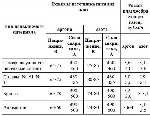
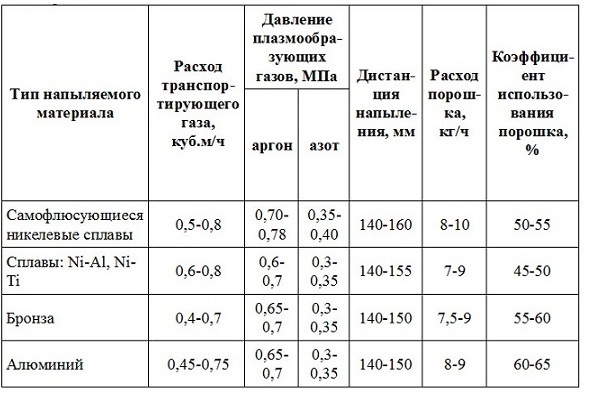
3) Coating. Depending on the purpose and the materials being sprayed, coatings are sprayed in modes that include the following parameters: current strength (A), voltage (V), working gas flow rate (m 3 /s), powder particle size (μm), spraying distance (mm) .
The deposition is carried out in one pass of the plasma torch at a speed that provides a thickness of 15-100 microns.
To obtain a uniform coating thickness on the edges of the parts, it is necessary to ensure that the jet exits the edge of the part at a distance of at least half the spraying step, and each pass must overlap the previous one by one quarter of the width.
In the case of applying self-fluxing coatings, in order to increase the adhesion strength of the coatings to the substrate and reduce the porosity, the coatings are melted. Reflow of sprayed coatings can be performed gas burner, plasmatron, in a furnace, high-frequency current and in salt melts.
4) Quality control of deposited coatings. The control method is chosen depending on the properties of the coating, the type and purpose of the part:
a) the carving method is used for soft coatings such as silver. The surface of the coating is carved for at least 15-20 s. For scarification, brass or steel brushes with a wire diameter of 0.15- 0.25 mm . Brush rotation speed 1800-2500 rpm. After kartsevanie on the controlled surface should not be observed swelling and flaking of the coatings.
b) the method of applying a grid of scratches to the sprayed surface with a sharp knife, several parallel lines are applied, deep to the base metal of the substrate at a distance of 2- 3 mm from each other and the same number of parallel lines, perpendicular to them. There should be no swelling and peeling of the coatings on the surface of the coating.
c) heating method. The sprayed parts are heated for an hour at a temperature, depending on the coating material, up to 300 C, followed by cooling in air. Due to the difference in thermal expansion coefficients, with a weak adhesive strength, the coating swells and partially peels off.
Thin-film metal-polymer materials (metallized polymers, metal products with a thin polymer coating, multilayer systems, etc.) formed by vacuum technology are characterized by high service properties and are effectively used in solving various technical problems. Their application largely determined the achievements of optics, electrical and radio engineering, chemical technology, and a number of other industries. At the same time, even wider use of vacuum-plasma methods in the formation of thin-film metal-polymer materials is possible in the near future, which is associated, firstly, with the development of technical equipment, with the development and implementation of highly efficient technological processes, in particular, with the use of continuous automatic vacuum installations and, secondly, with noticeable success in studying the patterns of deposition of vacuum metal and polymer coatings.
The main feature of the formation of these materials is the occurrence of complex physical and chemical processes at the phase boundary, their dependence on the conditions and modes of layer deposition. It is for this reason that consideration of even the technologically simplest two-layer metal-polymer system implies, in particular, taking into account the state of the boundary polymer layer as its main element. The structure and properties of this layer are determined by the kinetics of diffusion, contact chemical processes, which, as a rule, have a relaxation nature and depend on the nature of the interacting materials and the technological parameters of the formation of an adhesive contact. At present, a large amount of experimental material has been accumulated on the nature and mechanism of interfacial interactions, the structure and properties of boundary layers, and the influence on the features and characteristics of interfacial processes of the nature of interacting materials and external thermal and mechanical influences. Theoretical studies, the main purpose of which is the analytical description of interfacial processes, are less numerous, which is explained by the complexity of the ongoing processes, the influence of a large number of factors, the degree and nature of the impact of which on interfacial processes have not been studied in detail.
Vacuum coating
Vacuum coating- the transfer of particles of the sprayed substance from the source (the place of its transfer into the gas phase) to the surface of the part is carried out along rectilinear trajectories at a vacuum of 10 -2 Pa and below (vacuum evaporation) and by diffusion and convective transfer in plasma at pressures of 1 Pa (cathode sputtering) and 10 -1 -10 -2 Pa (magnetron and ion-plasma sputtering). The fate of each of the particles of the sprayed substance upon impact with the surface of the part depends on its energy, the surface temperature, and the chemical affinity of the materials of the film and the part. Atoms or molecules that have reached the surface can either be reflected from it, or adsorbed and leave it after some time (desorption), or adsorbed and form a condensate on the surface (condensation). At high particle energies, high surface temperature, and low chemical affinity, the particle is reflected by the surface. The surface temperature of the part, above which all particles are reflected from it and the film is not formed, is called the critical temperature of vacuum deposition; its value depends on the nature of the film materials and the surface of the part, and on the state of the surface. At very low fluxes of evaporating particles, even if these particles are adsorbed on the surface, but rarely occur with other similar particles, they are desorbed and cannot form nuclei; film does not grow. The critical flux density of evaporated particles for a given surface temperature is the lowest density at which the particles condense and form a film. The structure of the deposited films depends on the properties of the material, the state and temperature of the surface, and the deposition rate. The films can be amorphous (glassy, eg oxides, Si), polycrystalline (metals, alloys, Si), or single crystalline (eg, semiconductor films obtained by molecular beam epitaxy). To streamline the structure and reduce the internal mechanical stresses of the films, increase the stability of their properties and improve adhesion to the surface of products immediately after deposition without breaking the vacuum, the films are annealed at temperatures slightly higher than the surface temperature during deposition. Often, by means of vacuum deposition, multilayer film structures are created from various materials.
Vacuum coating plants
Used for vacuum deposition technological equipment intermittent, semi-continuous and continuous action. Settings periodical action one cycle of film deposition is carried out for a given number of loaded products. Continuous installations are used in serial and mass production. They are of two types: multi-chamber and multi-position single-chamber. The former consist of sequentially arranged deposition modules, in each of which the deposition of films of certain materials or their heat treatment and control. The modules are interconnected by lock chambers and a transport conveyor device. Multi-position single-chamber installations contain several sputtering posts (located in one vacuum chamber) connected by a transport device of a conveyor or rotary type. The main components and systems of installations for vacuum deposition are independent devices, performing the specified functions:
- creating a vacuum
- evaporation or spraying of film material
- parts transportation
- control of vacuum deposition modes and film properties
- power supply
Vacuum spraying
Application of films or layers on the surface of parts or products under vacuum conditions (1.0 -1 10 -7 Pa). Vacuum deposition is used in the planar technology of semiconductor microcircuits, in the production of thin-film hybrid circuits, products of piezotechnics, acoustoelectronics, etc. (deposition of conductive, dielectric, protective layers, masks, etc.), in optics (deposition of antireflection, reflective, etc. coatings), limited - when metallizing the surface of plastic and glass products, car window tinting. Metals (Al, Au, Cu, Cr, Ni, V, Ti, etc.), alloys (for example, NiCr, CrNiSi), chemical compounds (silicides, oxides, borides, carbides, etc.), complex glass are applied by vacuum deposition. composition (for example, I 2 O 3 B 2 O 3 SiO 2 Al 2 O 3 CaO, Ta 2 O B 2 O 3 I 2 O 3 GeO 2), cermets.
Vacuum deposition is based on the creation of a directed flow of particles (atoms, molecules or clusters) of the deposited material on the surface of products and their condensation. The process includes several stages: the transition of the sprayed substance or material from the condensed phase to the gas phase, the transfer of gas phase molecules to the surface of the product, their condensation on the surface, the formation and growth of nuclei, and the formation of a film.
Typically, a vacuum deposition plant includes the following components:
- a working chamber in which films are deposited;
- sources of vaporized or sprayed materials with their power supply systems and control devices;
- evacuation and gas distribution systems that provide the necessary vacuum and the organization of gas flows (consist of pumps, leaks, valves, traps, flanges and covers, for measuring vacuum and gas flow velocities);
- power supply system and blocking of all devices and working units of the installation;
- a system for monitoring and controlling the vacuum deposition unit, which provides the specified deposition rate, film thickness, surface temperature of parts, annealing temperature, physical properties of films (contains a set of sensors connected via a control microprocessor computer with actuators and information output devices);
- conveying devices that ensure the input and output of parts into the working chamber, their precise placement at the deposition stations and transfer from one deposition position to another when creating a multilayer film system;
- accessory system and technological equipment(consist of intra-chamber screens, dampers, manipulators, hydraulic and pneumatic actuators, gas purification devices).
Vacuum deposition technologies are extremely energy intensive and are becoming a niche product in many countries. Many companies are replacing vacuum deposition with more productive and less expensive atmospheric plasma deposition.
Thermal vacuum spraying.
The thermal vacuum method for producing thin films is based on heating a substance in vacuum until its active evaporation and condensation of the evaporated atoms on the substrate surface. The advantages of the thin film deposition method by thermal evaporation include high purity of the deposited material (the process is carried out under high and ultrahigh vacuum), versatility (films of metals, alloys, semiconductors, dielectrics are deposited), and relative ease of implementation. The limitations of the method are uncontrolled deposition rate, low, variable and unregulated energy of the deposited particles.
The substance to be sprayed is placed in a heating device (evaporator), where it evaporates intensively at a sufficiently high temperature. In the vacuum, which is created inside the chamber by special pumps, the molecules of the evaporated substance freely and rapidly propagate into the surrounding space, reaching, in particular, the surface of the substrate. If the substrate temperature does not exceed the critical value, the substance condenses on the substrate, that is, the film grows. At the initial stage of evaporation, in order to avoid contamination of the film due to impurities adsorbed by the surface of the evaporated substance, as well as to bring the evaporator to operating temperature a damper is used to temporarily block the flow of the substance onto the substrate. Depending on the functional purpose film during the deposition process, the deposition time, thickness, electrical resistance or some other option. Upon reaching the set value of the parameter, the damper again blocks the flow of the substance and the process of film growth stops. Heating the substrate with a heater before deposition promotes the desorption of atoms adsorbed on its surface, and during deposition creates conditions for improving the structure of the growing film. A continuously operating pumping system maintains a vacuum of the order of 10-4 Pa.
The heating of the evaporated substance to temperatures at which it evaporates intensively is carried out by an electron or laser beam, microwave radiation, using resistive heaters (by direct transmission electric current through a sample of the desired substance or heat transfer from a heated coil). In general, the method is distinguished by great diversity both in terms of the methods of heating the evaporated substance and in the designs of evaporators.
If it is required to obtain a film from a multicomponent substance, then several evaporators are used. Since the evaporation rates of different components are different, it is rather difficult to ensure the reproducibility of the chemical composition of the obtained multicomponent films. Therefore, the method of thermal vacuum deposition is used mainly for pure metals.
The entire process of thermal vacuum deposition can be divided into three stages: the evaporation of atoms of a substance, their transfer to the substrate, and condensation. Evaporation of matter from the surface takes place, generally speaking, at any temperature other than absolute zero. If we assume that the process of evaporation of molecules (atoms) of a substance proceeds in a chamber whose walls are sufficiently heated and do not condense vapor (reflect molecules), then the evaporation process becomes equilibrium, that is, the number of molecules leaving the surface of the substance is equal to the number of molecules returning to substance. The vapor pressure corresponding to the equilibrium state of the system is called the pressure of saturated vapor, or its elasticity.
Practice shows that the process of film deposition on a substrate occurs at a rate acceptable for production if the saturated vapor pressure is approximately equal to 1.3 Pa. The temperature of a substance at which pi = 1.3 Pa (pi is the saturated vapor pressure at the evaporation temperature) is called the conditional temperature Tusl. For some substances, the conditional temperature is higher than the melting point Tm, for some it is lower. If Tusl< Тпл, то это вещество можно интенсивно испарять из твердой фазы (возгонкой). В противном случае испарение осуществляют из жидкой фазы. Зависимости давления насыщенного пара от температуры для всех веществ, используемых для напыления тонких пленок, представлены в различных справочниках в форме подробных таблиц или графиков
The second stage of thin film deposition is the transfer of substance molecules from the evaporator to the substrate. If the rectilinear and directed motion of molecules to the substrate is ensured, then a high material utilization factor can be obtained, which is especially important in the deposition of expensive materials. Other things being equal, this also increases the film growth rate on the substrate.
As the substance evaporates, the flow rate and radiation pattern for most types of evaporators gradually change. Under these conditions, sequential processing of immovable substrates leads to a scatter in the values of film parameters within a batch processed in one vacuum cycle. To improve reproducibility, the substrates are mounted on a rotating disk-carousel. As the carousel rotates, the substrates alternately and repeatedly pass over the evaporator, due to which the deposition conditions for each substrate are leveled and the effect of temporary instability of the evaporator is eliminated. The third stage of thin film deposition is the stage of condensation of atoms and molecules of a substance on the substrate surface. This stage can be conditionally divided into two stages: First stage– from the moment of adsorption of the first atoms (molecules) on the substrate to the moment of formation of a continuous coating, and the final stage, at which the film grows homogeneously to a given thickness.
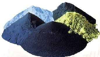
Powder coating of metal polymeric materials is by far the most modern and effective method obtaining a decorative protective coating metal products which are used in various branches of the national economy. At the moment, there are no analogues of powder coating on the market, since it has many undeniable economic and technological advantages, and, most importantly, does not harm the environment. Unlike traditional liquid paints, powder paints do not contain solvents in their composition, therefore they are completely safe both for people working with them and for the environment.
The powder used for metal spraying is a mixture of the smallest particles of rubber and a coloring pigment. In the spraying process, powder particles with an electrical charge are sprayed onto the surface of the product, which is neutral. This happens with the help of a special electrostatic spray gun. After the spraying is completed, the product made of metal (or other material) is transported to another room - a polymerization chamber, in which the powder is heated and softened. The paint melts and spreads over the surface in an even layer, resulting in a resistant, durable and very attractive coating, which also has protective properties.
The technology of powder spraying of metals is developing at a very fast pace, displacing traditional liquid paints from the market everywhere. Currently, work is underway to develop new methods of powder spraying, which contributes to its even greater distribution.
Powder coating of metal allows you to get a very high quality coating, which is a layer of powder deposited on the surface of the product, and then melted in a furnace at high temperature.
Thus, powder coating consists of three main stages:
- Surface pre-treatment and preparation for spraying. It consists in the removal of oxides and contaminants, phosphating and degreasing to ensure good adhesion and protect the painted product from corrosion.
- Direct application of a layer of powder paint on a metal part in a spray booth.
- Heating and polymerization of the powder layer in the polymerization chamber, the formation of a strong film, cooling and curing.
For powder coating of metal products, special painting lines are used, which can be automatic, semi-automatic and manual. For spraying large structures, a special transport system is provided, which moves them from chamber to chamber. The principle of its operation is that the painted objects are fed on trolleys or suspensions that move along rails. With the help of a transport system, a continuous spraying process can be ensured, which significantly increases the productivity of painting lines.
At the beginning of the powder coating process, metal parts are loaded onto a conveyor belt and sent to a pre-treatment chamber. There they are fed into a five-stage purifier and are treated with a purifier, phosphating, anti-corrosion treatment, and then rinsed. clean water. After that, the products are dried in a special oven. This is done in order to completely exclude moisture from entering the surface. After drying, the products are cooled. Then they are moved to the spray booth and powder is sprayed on them. In the polymerization chamber, it melts and a high-quality coating is obtained.
It must be said that metal powder coating allows you to get very quality coatings. This is achieved due to the fact that at all stages production process constant monitoring is carried out. For this, apply modern equipment. For example, a tomograph is used for qualitative control of polymerization parameters and the formation of coatings on the surface of parts. The degree of charge of the powder paint is also controlled, as well as the grounding of the parts.
At plasma method During coating application, the sprayed material is heated to a liquid state and transferred to the surface to be treated by means of a high-temperature plasma flow. The material to be sprayed is available in the form of rods, powders or wires. Powder method the most common.
The uniqueness of the plasma spraying method lies in the high temperature (up to 50 thousand degrees Celsius) of the plasma jet and the high speed (up to 500 m/s) of particles in the jet. The heating of the sprayed surface is small and does not exceed 200 degrees.
The productivity of plasma spraying is 3-20 kg/h for plasma generators with a capacity of 30...40 kW and 50-80 kg/h for equipment with a capacity of 150...200 kW.
The adhesion strength of the coating to the surface of the part is on average 10-55 MPa for separation, and in some cases up to 120 MPa. The porosity of the coating is in the range of 10...15%. The coating thickness is usually no more than 1 mm, since when it increases, stresses arise in the sprayed layer, tending to separate it from the surface of the part.
Plasma-arc spraying in combination with simultaneous surface treatment with a rotating metal brush makes it possible to reduce the coating porosity to 1-4%, and increase the total spraying thickness to 20 mm.
Plasma-forming gases are nitrogen, helium, argon, hydrogen, their mixtures and a mixture of air with methane, propane or butane.
Plasma spraying uses wire, including powder type, powders from ferrous and non-ferrous metals, nickel, molybdenum, chromium, copper, metal oxides, metal carbides and their compositions with nickel and cobalt, metal alloys, composite materials (nickel-graphite, nickel-aluminum, etc.) and mechanical mixtures of metals, alloys and carbides. The regulation of the spraying mode makes it possible to apply both refractory and low-melting materials.
Metals and non-metals (plastic, brick, concrete, graphite, etc.) can serve as the basis for plasma spraying. To apply coatings on small surfaces, a microplasma spraying method is used, which saves the loss of the sprayed material (spraying width 1-3 mm).
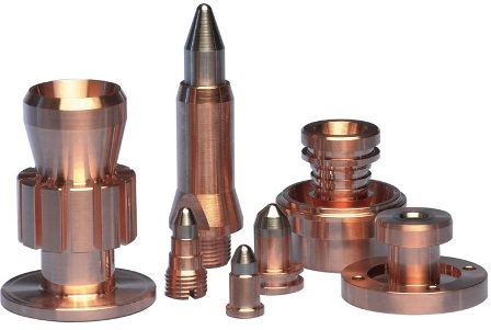
Plasma torch details
In order to increase the adhesion of sprayed coatings, protect against oxidation, reduce porosity, the method of plasma spraying is used in a protective environment (vacuum, nitrogen, a mixture of nitrogen with argon and hydrogen) and with the use of special nozzles that cover the area between the sprayer and the treated surface. A promising direction in plasma spraying technology is supersonic spraying.
The plasma spraying process includes 3 main stages:
1) Surface preparation.
2) Spraying and additional coating treatment to improve properties.
3) Machining to achieve finishing dimensions.
The preliminary dimensions of the surfaces to be sprayed must be determined taking into account the thickness of the spray and the allowance for subsequent machining. Surface transitions should be smooth, without sharp corners, in order to avoid peeling of the coating. The ratio of the groove width or hole diameter to its depth must be at least 2.
Parts must be thoroughly cleaned and degreased before spraying. Repair parts with oily grooves or channels should be heated in an oven at a temperature of 200-340 degrees. for 2-3 hours to evaporate the oil.
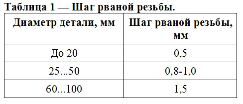
Next, the surface is activated - giving it a certain roughness to ensure adhesion. Activation is carried out by blowing the part with compressed air with an abrasive or cutting a torn thread.
The abrasive is chosen with a grain size of 80 ... 150 according to GOST 3647, or iron / steel shot DChK, DSK No. 01 ... 05 according to GOST 11964 is used.
Metal shot is not used for processing heat-resistant, corrosion-resistant steels and non-ferrous metals and alloys, since it can cause their oxidation.
(banner_direct2)
The surface roughness for plasma spraying should be 10...60 Rz, the surface should be matte.
Surfaces that are not subject to abrasive treatment are protected by screens. The airflow area must be 5+/-2 mm larger than the nominal size of the sprayed surface.
Thin parts are fixed in fixtures to prevent them from warping during processing.
The distance from the nozzle to the workpiece during abrasive blasting should be within 80 ... 200 mm, smaller values are taken for harder materials, larger ones for soft ones. After that, the parts are dedusted by blowing with compressed air.
The time interval between cleaning and spraying should be no more than 4 hours, and when spraying aluminum and other rapidly oxidizing materials - no more than an hour.
Torn thread cutting instead of abrasive blasting is used for parts with the shape of bodies of revolution. The thread is cut into lathe with a conventional threaded cutter, offset below the axis of the part. The thread is cut without cooling in one pass. The thread pitch is selected according to table 1.
For plasma spraying, powders of the same fraction should be used, the shape of the particles is spherical. Optimal size particles for metals is about 100 microns, and for ceramics - 50...70 microns. If the powders were stored in leaky containers, they must be calcined at a temperature of 120 ... 130 degrees for 1.5-2 hours in an oven.
Those parts of the part that are not sprayed are protected by asbestos or metal screens, or by coatings.
The preliminary heating of the part before spraying is carried out by a plasma torch to a temperature of 150 ... 180 degrees.
Processing modes are determined empirically. The average values of plasma spraying modes are as follows:
1) The distance from the nozzle to the part is 100...150 mm.
2) Jet speed — 3...15 m/min.
3) The speed of rotation of the part is 10 ... 15 m / min.
4) Spray angle - 60...90 degrees.
The total thickness of the coating is gained in several cycles with overlapping of the deposition strips by 1/3 of the diameter of the deposition spot.
After deposition, the part is removed from the plasma torch, protective screens are removed and cooled to room temperature.
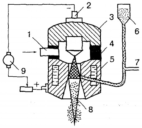
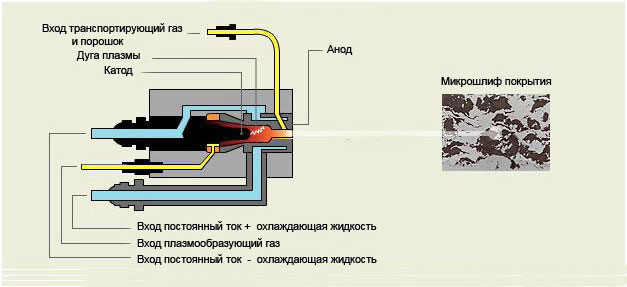
Picture 1 - circuit diagram plasma powder spraying: 1 - plasma gas supply, 2 - plasma torch cathode, 3 - cathode housing, 4 - insulator, 5 - anode housing, 6 - powder feeder, 7 - powder carrier gas supply, 8 - plasma arc, 9 - source nutrition.
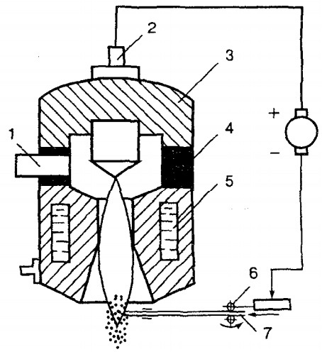
Figure 2 - Schematic diagram of plasma spraying using wire: 1 - plasma gas supply, 2 - plasma torch cathode, 3 - cathode case, 4 - insulator, 5 - anode case, 6 - wire feed mechanism, 7 - solid or flux-cored wire, 8 - plasma arc, 9 - power source.
Figure 3 - The structure of the coating sprayed by the plasma method
To improve the quality of sprayed coatings, the following methods are used:
1) running in rollers under electric current;
2) spraying with simultaneous processing with metal brushes;
3) melting of coatings from self-fluxing alloys. Reflow is carried out using furnaces, high-frequency current, heated molten salts and metals, plasma, laser or gas-flame methods. The melting temperature of the nickel-chromium-boron-silicon-carbon coating is 900..1200 degrees.
The final dimensions of parts after plasma spraying are obtained by turning and grinding with cooling with aqueous solutions and water-oil emulsions. Grinding wheels are selected from electrocorundum grade E on a ceramic bond, grain size 36 ... 46, hardness CH. Grinding modes are as follows: wheel rotation speed 25...30 m/s, wheel feed 5...10 mm/rev, workpiece rotation speed 10...20 m/min, workpiece feed 0.015...0.03 mm/ dv.h.
Further, the final control is carried out, if there are cracks, delaminations, risks, blackness on the surface of the part with spraying, finishing dimensions are not maintained, then the part is returned for defect correction (no more than 1 time), while the spraying area should be increased by 10 ...15 mm around the perimeter.


How to understand: will the kitten be fluffy?
What kind of light alcohol can be drunk for pregnant women: the consequences of drinking
Why do the legs swell in the ankles and ankles of the feet in pregnant women: causes and methods of treatment
The wedding of Prince Harry and Meghan Markle: scandalous and secret details of the marriage (photo) The future marriage of Prince Harry year NTV
How to close white plums for the winter