At plasma method During coating application, the sprayed material is heated to a liquid state and transferred to the surface to be treated by means of a high-temperature plasma flow. The material to be sprayed is available in the form of rods, powders or wires. Powder way the most common.
The uniqueness of the plasma spraying method lies in the high temperature (up to 50 thousand degrees Celsius) of the plasma jet and the high speed (up to 500 m/s) of particles in the jet. The heating of the sprayed surface is small and does not exceed 200 degrees.
In this text, we assume that the thin film has a thickness from a few nanometers to about 100 µm. The film can then be locally etched using the processes described in the Lithography and Etching sections of this manual. The solid material is usually not the only product formed from the reaction. By-products can include gases, liquids, and even other solids.
Common to all these processes is that the deposited material is physically transferred to the substrate. In other words, there is no chemical reaction that forms the material on the substrate. This is not entirely correct for casting processes, although it is more convenient to think of them that way.
The productivity of plasma spraying is 3-20 kg/h for plasma generators with a capacity of 30...40 kW and 50-80 kg/h for equipment with a capacity of 150...200 kW.
The adhesion strength of the coating to the surface of the part is on average 10-55 MPa for separation, and in some cases up to 120 MPa. The porosity of the coating is in the range of 10...15%. The coating thickness is usually no more than 1 mm, since when it increases, stresses arise in the sprayed layer, tending to separate it from the surface of the part.
Chemical Vapor Deposition
This is far from full list because technology is constantly evolving. In this process, the substrate is placed in a reactor to which a series of gases are fed. The basic principle of the process is that between the source gases there is chemical reaction. The product of this reaction is a solid material that condenses on all surfaces inside the reactor.
The main problems of the process are the high settling temperature and the relatively slow settling rate. However, the quality of the films is, as a rule, worse than the processes proceeding at higher temperatures. A variety of materials can be applied with this technology, however some are less popular with factories due to hazardous by-products generated during processing. The quality of the material varies from process to process, however good rule is that a higher process temperature produces a material with higher quality and fewer defects.
Plasma-arc spraying in combination with simultaneous surface treatment with a rotating metal brush makes it possible to reduce the coating porosity to 1-4%, and increase the total spraying thickness to 20 mm.
Plasma-forming gases are nitrogen, helium, argon, hydrogen, their mixtures and a mixture of air with methane, propane or butane.
This process is also known as "electroplating" and is generally limited to electrically conductive materials. There are basically two coating technologies: electroplating and chemical processing. In the electroplating process, the substrate is placed in a liquid solution. When an electrical potential is applied between the conductive region on the substrate and the counter electrode in the liquid, a chemical redox process occurs, resulting in the formation of a layer of material on the substrate and, typically, some generation of gas at the counter electrode.
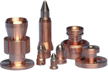
Plasma spraying uses wire, including powder type, powders from ferrous and non-ferrous metals, nickel, molybdenum, chromium, copper, metal oxides, metal carbides and their compositions with nickel and cobalt, metal alloys, composite materials (nickel-graphite, nickel-aluminum, etc.) and mechanical mixtures of metals, alloys and carbides. The regulation of the spraying mode makes it possible to apply both refractory and low-melting materials.
The chemical deposition process uses a more complex chemical solution in which the deposition occurs spontaneously on any surface that forms a sufficiently high electrochemical potential with the solution. This process is desirable because it does not require an external electrical potential and is not in contact with the substrate during processing. Unfortunately, it is also difficult to control film thickness and uniformity. The figure below shows a diagram of a typical electroplating installation.
The electrodeposition process is well suited for making films of metals such as copper, gold, and nickel. Deposition is best controlled when used with an external electrical potential, however, immersion in a liquid bath requires electrical contact with the substrate. In any process, the surface of the substrate must have an electrically conductive coating prior to deposition.
Metals and non-metals (plastic, brick, concrete, graphite, etc.) can serve as the basis for plasma spraying. To apply coatings on small surfaces, a microplasma spraying method is used, which saves the loss of the sprayed material (spraying width is 1-3 mm).
Working installations for the implementation of the process
Figure 2: Typical setup for electrodeposition. In this process, a series of gases are introduced into an induction heated reactor where only the substrate is heated. The temperature of the substrate should typically be at least 50% of the melting point of the material to be deposited. The advantage of epitaxy is the high growth rate of the material, which makes it possible to create films with a significant thickness. Epitaxy is a widely used technology for the production of silicon on insulator substrates. This technology is mainly used for silicon deposition.
Plasma torch details
In order to increase the adhesion of sprayed coatings, protect against oxidation, reduce porosity, the method of plasma spraying is used in a protective environment (vacuum, nitrogen, a mixture of nitrogen with argon and hydrogen) and with the use of special nozzles that cover the area between the sprayer and the treated surface. A promising direction in plasma spraying technology is supersonic spraying.
The figure below shows the schematic of a typical vapor phase epitaxial reactor. Figure 3: Typical epitaxial cold wall vapor phase reactor. Some processes require high temperature exposure to the substrate, while others do not require significant heating of the substrate. Some processes can even be used to perform selective deposition depending on the surface of the substrate.
It is one of the most basic deposition technologies. This is simply the oxidation of the substrate surface in an oxygen-rich atmosphere. It is also the only deposition technology that actually absorbs some of the substrate as it comes in. The film growth is cured by diffusion of oxygen into the substrate, which means that the film growth is actually down into the substrate. As the thickness of the oxidized layer increases, oxygen diffusion to the substrate becomes more difficult, resulting in a parabolic relationship between film thickness and oxidation time for films thicker than ~100 nm.
The plasma spraying process includes 3 main stages:
1) Surface preparation.
2) Spraying and additional coating treatment to improve properties.
3) Mechanical restoration to reach the final dimensions.
The preliminary dimensions of the surfaces to be sprayed must be determined taking into account the thickness of the spray and the allowance for subsequent machining. Surface transitions should be smooth, without sharp corners, in order to avoid peeling of the coating. The ratio of the groove width or hole diameter to its depth must be at least 2.
This process is naturally limited to materials that can be oxidized, and it can only form films that are oxides of that material. This is the classical process used to form silicon dioxide on a silicon substrate. The diagram below shows the layout of a typical plate oxidation furnace.
Physical vapor deposition
It is commonly used to form films that are used for electrical insulation or that are used for other technological processes later in the process sequence. Figure 4: Typical wafer oxidation furnace. The two most important technologies are evaporation and spraying.
Parts must be thoroughly cleaned and degreased before spraying. Repair parts with oily grooves or channels should be heated in an oven at a temperature of 200-340 degrees. for 2-3 hours to evaporate the oil.
Next, the surface is activated - giving it a certain roughness to ensure adhesion. Activation is carried out by blowing the part with compressed air with an abrasive or cutting a torn thread.
The choice of deposition method in many cases can be arbitrary and may depend more on what technology is available for the particular material at the time. During evaporation, the substrate is placed in a vacuum chamber, which also contains a block of material to be deposited. The starting material is then heated until it begins to boil and evaporate. The vacuum is needed to allow the molecules to evaporate freely in the chamber and they subsequently condense on all surfaces. This principle is the same for all evaporation technologies, only the method used for heating differs from the source material.
The abrasive is chosen with a grain size of 80 ... 150 according to GOST 3647, or iron / steel shot DChK, DSK No. 01 ... 05 according to GOST 11964 is used.
Metal shot is not used for processing heat-resistant, corrosion-resistant steels and non-ferrous metals and alloys, since it can cause their oxidation.
(banner_direct2)
The surface roughness for plasma spraying should be 10...60 Rz, the surface should be matte.
Technological equipment, consumables
There are two popular evaporation technologies, electron beam evaporation and resistive evaporation, each of which refers to a heating method. In electron beam evaporation, the electron beam is directed at the source material, causing local heating and evaporation. In resistive evaporation, the tungsten boat containing the raw material is heated electrically with a large current to vaporize the material. Many materials are restrictive in terms of what evaporation method can be used, which is usually related to the phase change properties of that material.
Surfaces that are not subject to abrasive treatment are protected by screens. The airflow area must be 5+/-2 mm larger than the nominal size of the sprayed surface.
Thin parts are fixed in fixtures to prevent them from warping during processing.
The distance from the nozzle to the workpiece during abrasive blasting should be within 80 ... 200 mm, smaller values are taken for harder materials, larger ones for soft ones. After that, the parts are dedusted by blowing with compressed air.
The figure below shows a diagram of a typical electron beam evaporation system. Figure 5: Typical system for electron beam evaporation of materials. Atomization is a technology where material is released from a source at a much lower temperature than evaporation. The substrate is placed in a vacuum chamber with the source material, called the target, and an inert gas is introduced at low pressure. The ions are accelerated towards the target surface, causing the atoms of the starting material to detach from the target in the form of a vapor and condense on all surfaces, including the substrate.
The time interval between cleaning and spraying should be no more than 4 hours, and when spraying aluminum and other rapidly oxidizing materials - no more than an hour.
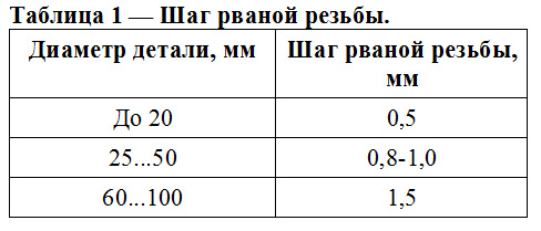
Torn thread cutting instead of abrasive blasting is used for parts with the shape of bodies of revolution. The thread is cut into lathe with a conventional threaded cutter, offset below the axis of the part. The thread is cut without cooling in one pass. The thread pitch is selected according to table 1.
With regard to evaporation, the basic principle of atomization is the same for all atomization technologies. The differences are usually related to the homestead in which the ion bombardment of the target takes place. In this process, the material to be deposited is dissolved in liquid form in a solvent. The material can be applied to the substrate by spraying or molding. Once the solvent is evaporated, a thin film of material remains on the substrate. This is especially useful for polymer materials, which can be easily dissolved in organic solvents, and is a common technique used to apply photoresist to substrates.
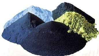
For plasma spraying, powders of the same fraction should be used, the shape of the particles is spherical. Optimal size particles for metals is about 100 microns, and for ceramics - 50...70 microns. If the powders were stored in leaky containers, they must be calcined at a temperature of 120 ... 130 degrees for 1.5-2 hours in an oven.
The thicknesses that can be cast onto a substrate range from a single monolayer of molecules to tens of micrometers. In recent years, casting technology has also been used to produce films from glass materials on substrates. The injection molding process is shown in the figure below.
The casting is simple technology, which can be used for various materials. If you plan to use photolithography, you will use casting, which is an integral part of this technology. There are also other interesting materials such as polyimide and spin glass that can be applied by casting.
Those parts of the part that are not sprayed are protected by asbestos or metal screens, or by coatings.
The preliminary heating of the part before spraying is carried out by a plasma torch to a temperature of 150 ... 180 degrees.
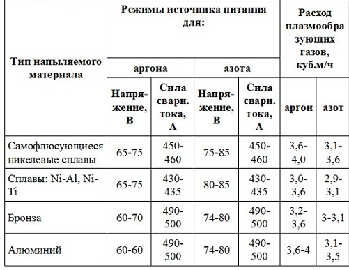
Processing modes are determined empirically. The average values of plasma spraying modes are as follows:
Figure 7: The injection molding process used for photoresist in photolithography. Today more than ever, consumer goods manufacturers are using coatings to add value to their products. As far as "metallic effect" coatings are concerned, metals are mainly manufactured with high resistance to abrasion and chemicals, in particular chromium and stainless steel deposits, transition carbides and nitrides. Not only are they tough and durable, but they can also be given innovative colors for decorative purposes that are applied to consumer product surfaces.
1) The distance from the nozzle to the part is 100...150 mm.
2) Jet speed — 3...15 m/min.
3) The speed of rotation of the part is 10 ... 15 m / min.
4) Spray angle - 60...90 degrees.
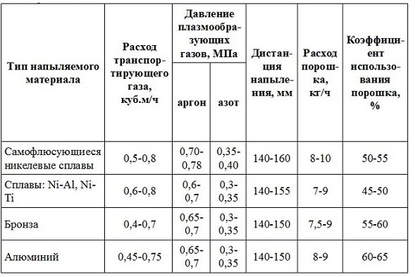
The total thickness of the coating is gained in several cycles with overlapping of the deposition strips by 1/3 of the diameter of the deposition spot.
Spraying is not only the cleanest coating technology, but also offers many advantages like no other technique: spraying in particular is economically effective way production that can provide as thin and uniform a coating as possible. It is a dry process at low temperature.
An unbreakable bond is formed between the film and the substrate. This provides more versatility than other coatings as it is a cold layer that can be used to deposit conductive or non-conductive materials on any substrate including metal, ceramic and plastic i.e. hour heat sensitive materials.
After deposition, the part is removed from the plasma torch, protective screens are removed and cooled to room temperature.
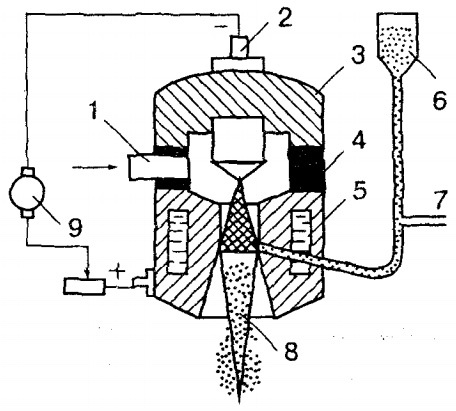
Picture 1 - circuit diagram plasma powder spraying: 1 - plasma gas supply, 2 - plasma torch cathode, 3 - cathode housing, 4 - insulator, 5 - anode housing, 6 - powder feeder, 7 - powder carrier gas supply, 8 - plasma arc, 9 - source nutrition.
In addition, this process is possible to control the deposition, which can be repeated automatically. That is why this solution is being adapted to create new, more sustainable, lighter, cleaner and more economical materials that will revolutionize not only our industry, but also everyday life.
Spray coating is one of the most flexible vapor deposition methods. The coating material is introduced into the vacuum chamber in the form of a cathode in the form of a metal plate. After the chamber is empty, process gas is introduced. Attached high voltage and gas is introduced. The positive argon ions undergo an acceleration process on the negative cathode and the atoms fly out of the metal plate. They then fall onto the substrates already in the chamber and condense the desired metal coating on the substrate.
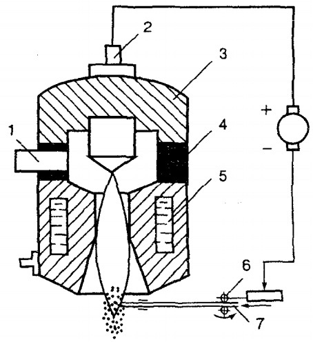
Figure 2 - Schematic diagram of plasma spraying using wire: 1 - plasma gas supply, 2 - plasma torch cathode, 3 - cathode case, 4 - insulator, 5 - anode case, 6 - wire feed mechanism, 7 - solid or flux-cored wire, 8 - plasma arc, 9 - power source.
Figure 3 - The structure of the coating sprayed by the plasma method
To improve the quality of sprayed coatings, the following methods are used:
1) running in rollers under electric current;
2) spraying with simultaneous processing with metal brushes;
3) melting of coatings from self-fluxing alloys. Reflow is carried out using furnaces, high-frequency current, heated molten salts and metals, plasma, laser or gas-flame methods. The melting temperature of the nickel-chromium-boron-silicon-carbon coating is 900..1200 degrees.
The final dimensions of parts after plasma spraying are obtained by turning and grinding with cooling with aqueous solutions and water-oil emulsions. Grinding wheels are selected from electrocorundum grade E on a ceramic bond, grain size 36 ... 46, hardness CH. Grinding modes are as follows: wheel rotation speed 25...30 m/s, wheel feed 5...10 mm/rev, workpiece rotation speed 10...20 m/min, workpiece feed 0.015...0.03 mm/ dv.h.
Further, the final control is carried out, if there are cracks, delaminations, risks, blackness on the surface of the part with spraying, finishing dimensions are not maintained, then the part is returned for defect correction (no more than 1 time), while the spraying area should be increased by 10 ...15 mm around the perimeter.
17.1. Classification of types of gas thermal spray.
Thermal spraying is a coating process based on heating the material to a liquid state and spraying it onto the product - the substrate using a gas jet.
Coatings are applied without a significant increase in the temperature of the substrate, which eliminates the appearance of deformation of the sprayed parts.
Thermal spraying can be divided into two groups (Fig. 17.1.):
1) flame;
2) gas-electric.
Rice. 17. 1. Classification of types of thermal spraying.
1) The essence of flame spraying is to melt the sprayed materials with a gas flame and spray them with compressed air (Fig. 13.2.)
Powder, solid wire and flux-cored wire or rods are used as the sprayed material. As a combustible gas, acetylene, propane-butane, natural gas, etc. are used. The disadvantages of gas-flame spraying are the low quality of coatings due to the low flame temperature, low particle transfer rates and a high content of oxides in the coating.
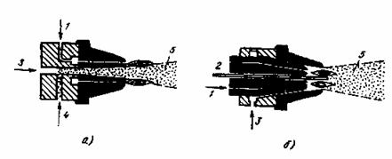
Figure 17.2. Scheme of spraying with a gas flame:
1 - combustible mixture; 2 - sprayed wire; 3 - compressed air;
4 - sprayed powder; 5 - metallization torch.
2) The essence of electrometallization spraying is to melt the wire with an electric arc and spray the liquid metal with compressed air. Spraying with compressed air leads to significant burnout of the components and their oxidation.
Electrometallizers are much easier to manage than flame ones. In electric arc spraying, wire is used as the starting material.
High-frequency metallizers, like electric arc, are wire-type devices. The heating of the wire is carried out by inducing high-frequency currents in it. HDTV lamp generators (70-500 kHz) are used as a power source. The performance of high-frequency metallizers is 1.5-2.5 times higher than the performance of electrometallization ones. The disadvantages of this method of deposition are the low efficiency of installations (15-20%), the relatively low adhesion strength of the deposited layer to the substrate.
Rice. 17.3. Scheme of electrometallization spraying:
a - electric arc, b - high-frequency: 1.3 - sprayed wire; 2 - compressed air; 4 - inductor; 5 - metallization torch.
17.2. The essence of plasma spraying.
One of the high-performance coating methods that uses low-temperature plasma is plasma spraying.
The physical concept of “plasma” was introduced in 1923 . Langmer to designate the gaseous state, in which gases become conductive due to the ionization of atoms. During plasma spraying, electrons, ions, and neutral particles occur in the jet. To ionize the plasma, an electric arc is used, and in order to increase the temperature, the arc is compressed, which sharply increases its temperature. The temperature of argon plasma reaches 20000-23000 C. Plasma spraying is widely used in those branches of mechanical engineering where it is necessary to protect machine parts from intense wear by applying various resistant alloys, increase the performance of wear parts several times, protect parts from corrosion, erosion, cavitation, abrasive wear, thermal shocks, etc. The thickness of the deposited layers varies from 0.03mm up to several millimeters.
Sprayed coatings have the following advantages: high density; strong adhesion to the base material; smooth surface spraying, which does not require subsequent machining (grinding); relatively low consumption of sprayed material compared to other methods.
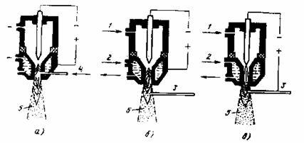
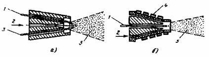
Figure 17.4. Plasma spraying schemes.
a - supply of the sprayed material into the plasma jet through the nozzle; b - the same behind the nozzle section; c - plasma metallization with a dependent arc wire; 1 - gas input; 2 - water input; 3 - electrode wire; 4 - powder supply; 5 - metallization torch.
Metallization with wire is carried out by an independent or dependent arc.
Argon, nitrogen, ammonia, helium and argon-hydrogen mixtures are used as plasma-forming gases. The best gas to protect the tungsten electrode is the inert gas argon.
The sprayed materials are made in the form of powder or wire. The advantages of plasma spraying with powder materials (compared to wire materials) are as follows: more uniform (without post-treatment) and finer coating structure; the possibility of obtaining combined coatings and so-called pseudo-alloys by mixing powders from various materials; low cost.
For plasma spraying, spherical powders with a granulation of 5-100 microns are most suitable.
17.3. Equipment for plasma spraying.
The installation is designed for spraying coatings using a plasma jet. The installation kit includes the following components: a DC power supply (complete with a rectifier or converter), a control cabinet, a plasma torch, a feeder for dosing and supplying powder to the spraying zone, and a connecting cable.
The installation provides mechanized wire or powder feeding into the plasma torch, maneuverability and the possibility of applying coatings in hard-to-reach places.
Spraying is carried out on direct current from a power source with a supplying external characteristic.
The installation is usually equipped with a plasma torch for manual powder spraying and a plasma torch for wire metallization.
For deposition, an indirect plasma arc is used between a cooled tungsten cathode and a copper nozzle (anode).
The main parts of the plasma torch are electrodes - cathode and anode. When working in inert media, rods of thoriated tungsten of grades VT 10 and VT 15 and grades VT 30, VT 50, VRN lanthanated tungsten grade VL or pure tungsten mugs are used as the cathode material. In the case of using oxygen- or nitrogen-containing plasma-forming media, it is recommended to use composite alloys as the material of the non-consumable electrode.
Plasmatrons are classified:
1) by the method of arc stabilization (gas, water and magnetic);
2) according to the method of gas supply (along the column or perpendicular to it), gas stabilization can be axial or vortex. The greatest compression of the arc is achieved with vortex stabilization. The axial stabilization system provides a laminar plasma flow and a satisfactory formation of the plasma arc column in the channel of the electrically conductive nozzle.
3) according to the type of material supplied to the arc column (powder, wire and rod material). Plasmatrons designed to work with powdered materials are most widely used in the practice of deposition, which makes it possible to change the chemical composition of the coating and its physical and mechanical properties over a wide range.
The sprayed material is introduced into the plasma flow in three ways (Figure 17.4): before the anode spot of the arc, in the area of the anode spot of the arc, after the anode spot (into the plasma jet). In each of the options, the material is fed radially, tangentially and in the longitudinal direction. At present, the most common way to introduce powder is to introduce it after the anode spot of the arc (into the plasma jet).
17.4. Plasma spraying technology.
Plasma spraying technology includes several successive operations: preparation of powders and the sprayed surface, coating spraying, coating processing and quality control.
1) Preparation of powders. For coating by spraying, powders with a granulation of 5-100 microns, and in some cases up to 160 microns, are used. Fine powders are highly hygroscopic and clumpy. To increase their flowability before spraying, the powders are dried in an oven at a temperature of 70-200 0 C (depending on the composition of the powder) for 2 hours.
After drying and cooling, sieved on a mechanical or vibrating sieve. Drying of the powder is carried out no more than 2-3 hours before spraying.
2) Preparation of parts for spraying. The criterion for satisfactory adhesion of the coating to the substrate is the preparation of parts before spraying, carried out by one of the following methods: degreasing, etching, sandblasting (heating), machining.
Degreasing parts with gasoline is carried out to remove oil and dirt from the metal surface.
Sandblasting cleans the surface of the substrate and roughens it in processing, which increases the contact temperature under the sprayed particles on the protrusions of microroughnesses.
Heat treatment provides activation of the substrate surface. When sprayed in air, heating for most metals is limited to 100-200 0 C.
Machining is designed to obtain a rough surface of the substrate by cutting or grinding.
3) Coating. Depending on the purpose and the materials being sprayed, coatings are sprayed in modes that include the following parameters: current strength (A), voltage (V), working gas flow rate (m 3 /s), powder particle size (μm), spraying distance (mm) .
The deposition is carried out in one pass of the plasma torch at a speed that provides a thickness of 15-100 microns.
To obtain a uniform coating thickness on the edges of the parts, it is necessary to ensure that the jet exits the edge of the part at a distance of at least half the spraying step, and each pass must overlap the previous one by one quarter of the width.
In the case of applying self-fluxing coatings, in order to increase the adhesion strength of the coatings to the substrate and reduce the porosity, the coatings are melted. Reflow of sprayed coatings can be performed gas burner, plasmatron, in a furnace, high-frequency current and in salt melts.
4) Quality control of deposited coatings. The control method is chosen depending on the properties of the coating, the type and purpose of the part:
a) the carving method is used for soft coatings such as silver. The surface of the coating is carved for at least 15-20 s. For scarification, brass or steel brushes with a wire diameter of 0.15- 0.25 mm . Brush rotation speed 1800-2500 rpm. After kartsevanie on the controlled surface should not be observed swelling and flaking of the coatings.
b) the method of applying a grid of scratches to the sprayed surface with a sharp knife, several parallel lines are applied, deep to the base metal of the substrate at a distance of 2- 3 mm from each other and the same number of parallel lines, perpendicular to them. There should be no swelling and peeling of the coatings on the surface of the coating.
c) heating method. The sprayed parts are heated for an hour at a temperature, depending on the coating material, up to 300 C, followed by cooling in air. Due to the difference in thermal expansion coefficients, with a weak adhesive strength, the coating swells and partially peels off.


Mixed Personality Disorder: Causes, Symptoms, Types and Treatments
GTA 4 control settings
FAQ on Smuggling in GTA Online
LSPDFR - welcome to the police
The huge map of Grand Theft Auto San Andreas and its secrets