CNC machine "on hastily»
Unexpectedly, many readers who read my article on some aspects of designing the mechanics of a home-made CNC engraving and milling machine expressed in their responses, as if it were softer ..., bewilderment at the fact that I mentioned linear ball bearings in passing and without due enthusiasm . Indeed, I did not waste my enthusiasm. I treat linear ball guides calmly, as one of options building a coordinate table. Like any other option, this one has its advantages and disadvantages, of which the main advantage is the relative technological simplicity of achieving the specified accuracy with working strokes of more than a meter, and the main disadvantage is the high price of components.
I still believe that a small machine, for example, with a working field of 500x300 mm, is easier, more technologically advanced and cheaper to make using round guides with bronze sliding bushings. However, the larger working field, the more difficult it is to provide a given accuracy for reasonable money. Finally, there comes a time when the technological difficulties in the manufacture and installation of sliding guides, and hence their cost, turn out to be comparable to the cost of blocks of linear ball bearings on rails.
So it turns out that a small engraving milling machine cheaper to do on round sliding guides with a conventional screw gear. But, if the working stroke on at least one of the axes exceeds a certain value at which it is more profitable to buy ball guides, then of course it is easier to buy. Of course, the mentioned "some value" is a relative thing. The cost of manufacturing mechanics in Moscow and, for example, in the Urals differs significantly. According to my estimates, for Moscow, the size of the stroke at which it is worth thinking about ball linear guides is 1000 ... 1200 mm or more.
The article was planned in two parts. The first part was to be devoted to the choice of guides, the design and construction of mechanics using ball linear guides, and the second - the practical implementation of the machine. It is known that no one likes to read theory, all are "theorists" themselves. Therefore, anticipating exclamations: “Everything that you write has long been known from books! Closer to practice!!”, I decided to limit myself to practical implementation. In general, the purpose of the article is not to teach how to build CNC machines, but to expand the horizons of those interested in such equipment and show that a CNC machine in production (but not at a price!) Is not such a cool thing as people think about it.
Task
Generally speaking, sandwiches and salads are made in a hurry, a romantic dinner can be built in haste, but not a machine. Nevertheless, I took out this phrase in the title of the article. Why? I'll try to explain.
“In haste” means technologically for home production. Those. the machine must be designed so that it can be made using the minimum set of the most common plumbing tools. Literally, if you have a jigsaw with a metal saw in your arsenal, drilling machine, tapping dies and a file, then this should be enough. At worst, a simple hacksaw and a drill will do.
Some will say: “Well, you turned down, comrade! It doesn't happen," and he would be right. That really doesn't happen. Because if milling work can be excluded completely, then we cannot do without elementary turning works, which means that there should not be many of these works at all, everything else should be done by pens, in the kitchen.
Setting such a task, one must be well aware that the plan can be realized only if purchased components and standard aluminum profiles are widely used. Guides - a sort of cornerstones of a portal engraving and milling machine - also have to be bought, but they are expensive. So, "in haste" does not mean cheap!
And the last consideration. "In a hurry" is associated with the concepts of simply and quickly. If one can agree with the definition of “simple”, then it is unlikely to succeed quickly. The production of even simple parts can take up to indefinite term, but as they say, "patience and work will grind everything."
To summarize:
- For milling balsa, plywood, wood, plastics and thin (up to 2 mm) aluminum alloys.
- On linear ball guides and toothed belts.
- The working field is at least 1000x300x90.
- Positioning resolution is not worse than 0.1 mm.
- Positioning speed not less than 2 m/min.
X
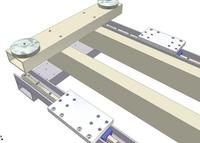
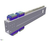
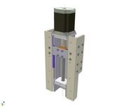
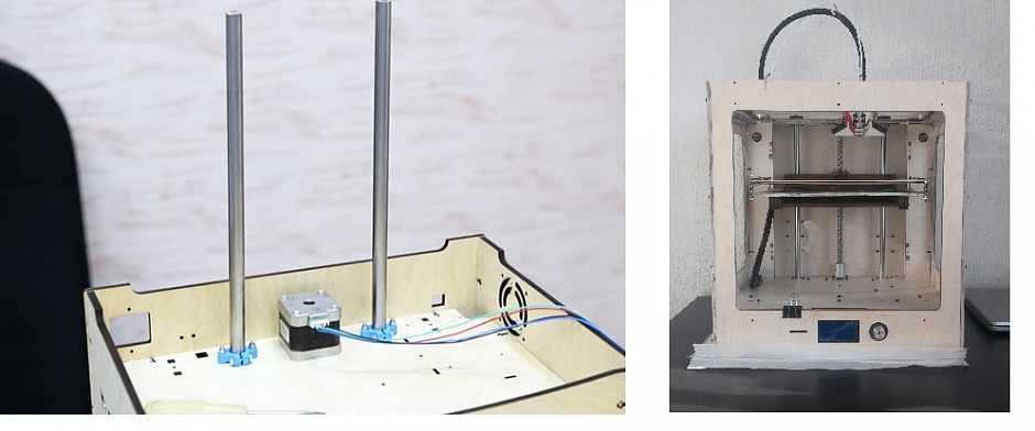
Let's start with a simple one - from the base table. An elementary geometric calculation shows that with a travel along X equal to 1000 mm, the length of the table should be 1300 mm. At least that's what happened to me. With a Y stroke greater than 300 mm, the width of the table must be at least 460 mm.
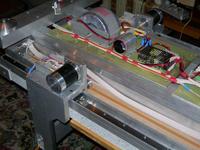
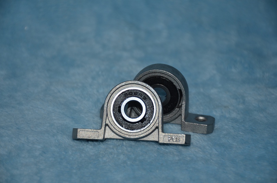
Having studied the assortment of standard pressed rectangular pipes (boxes) made of aluminum alloy AD31 (unfortunately, the industry does not produce others), we select a box 80x40x4 mm. We cut several beams from it (1300 mm - 2 pcs. and 460 mm - 4 pcs.). We also need two channels 50x30x4 1300 mm long. The ball guides SBS15SL, which I decided to use, fit perfectly into them. As legs, we use suitable round legs from the sofa, bought at the OBI store. We drill holes in all this, paint something, if possible, and assemble the base frame.
|
|

It turned out pretty solid. Under load, the channels into which the rails will be laid slightly bend, but that’s okay, we put the tabletop - it will be a completely different matter, the base will acquire exceptional “oakness” in terms of strength and rigidity.
We screw the rails.

They are located under the table and, as you can see, are relatively well protected from dust and chips. Despite the fact that SBS ball blocks are equipped with scrapers, it is never harmful to provide additional (passive) protection of the rails and blocks from direct chips.
We screw the platforms to the ball blocks, on which the portal will subsequently be placed. These platforms are simply rectangular plates made of D16T alloy with holes for mounting the portal and a bracket for a stepper motor.
Let's talk about the stepper motor bracket, and in general about the timing belt wiring.
Toothed belt wiring
Yes, stepper motors for moving the portal along the X axis will be mounted on the portal itself! For some reason, when they talk about a drive with a toothed belt, a belt is drawn in the brain in the form of a ring with a motor mounted on a frame, and the belt tension is organized on a portal or carriage. You can do this, but is it the best way? Not sure. We will go the other way. Let's arrange a pseudo gear rack from the belt.
Fasten the ends of the belt to the frame. We fix one clamping bar rigidly, and the other will be able to move to tension the belt within the distance between adjacent teeth, i.e. within 5 mm. The gear wheel, as usual, is mounted on the motor shaft. The rollers are mounted on the same bracket as the motor. In general, everything is obvious - the motor is spinning and moving itself.
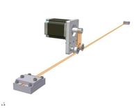
Why is this method better than an annular belt? Yes, at least the fact that the belt consumption is half as much, it is easier to tighten, saving on gear wheels, which are expensive and must be bought with the belt. Rollers with axles can be picked up ready-made. In general, there are advantages to this solution. What about the cons? Do not know…. Cables from the motors to carry behind the portal? So it’s all the same to drag them from the Y and Z axes, plus or minus a few wires - it doesn’t matter. Will the weight of the portal increase? will increase. And this is probably the only negative that is worth talking about. The issue price is 1.5 ... 2 kg (weight of motors) and / or 100 US dollars (long belt and additional gears). I chose to save money over weight. With such dimensions of the portal, saving two kilograms of its mass does not give a significant gain. In the end, when using gear racks, the motors are on the carriages.
The belt must be taken with a relatively small tooth. I chose a tail boom strap from the tail boom of a Raptor 50 model helicopter, dear to my heart. It has a 5mm tooth pitch. The gear wheel is also from this helicopter. Its diameter (along the midline of the teeth) is 14 mm. This means that when the engine is turned on in half-step mode (400 steps per revolution), the movement of the carriage by one step will be 3.14 * 16/400 = 0.11 mm. This is more than intended. In microstepping (1:6), the movement per step is 0.042 mm. What you need. And although the “non-stretching” belt still stretches a little, the belt does not contain the accumulated error that is always present in the lead screw. As a result, I think we will meet the milling accuracy of 0.1 mm for a length of 1000 mm. At least on balsa and 4mm plywood.
As for the stepper motor bracket, as you can see, this is a simple plate with holes. Nothing special, we cut it out in the same way as the base. So far, we have not gone beyond the scope of a hacksaw, drill and file. We will continue in the same spirit.
We install the whole thing on the frame and check how it rides. Rides well!
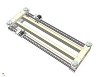
Actually, this is almost everything with a frame. It remains to "comb", give the product a "presentation" and install the countertop.
Marketable condition
"Made in at home" - not necessarily sloppy, clumsy and sloppy. I am depressing, mounted on ugly “chicken legs” and sticking out in all directions, engines, bundles of untidy wires, controllers turned inside out and similar “charms” improvised designs. Everything would be fine, in the end, everyone does as best they can, until the author of another such freak begins to seriously talk about the mass production of his offspring for sale, justifying the unsightly appearance of the machine by the fact that it is, they say, a prototype: “We’ll fix it here, we’ll redo it there , we will hang the casings, paint everything, and it will not be a machine, but a sweetie. Will not be! If for himself, his beloved, the author cannot do the right thing, and he is not ashamed to advertise his unfinished "product", then for the buyer he will do a blunder. Checked, and more than once. But this is so, by the way ....
Let's lay a couple of dead channels, which will house the cable loops from the motors and limit switches. If the controller is large and does not fit into the under-table space, then we will make brackets for the output connectors. And, finally, we will install plugs on the ends of the supporting profiles so that dirt does not accumulate in them.
Labor costs for these seemingly optional activities pay off with interest.
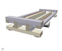
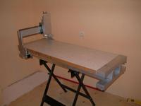
table top
The machine is planned mainly for sawing balsa, plywood, plastics, so the table top can be made from a laminated panel for kitchen furniture 40 mm thick, i.e. the same thickness as aluminum boxes. The tabletop is attached to the two supporting beams of the frame. The channels in which the rails are laid should also be attached with self-tapping screws to the tabletop. In general, the design is smooth, strong and rigid. You can safely stand on the resulting base of the machine and walk on it on foot - nothing will happen.
|
|
|


Some "advanced" professionals may like the type-setting worktop made of aluminum machine profile. Please, fundamentally nothing will change. However, a machine on toothed belts can only cut what it is designed for, namely, plywood, plastics and thin aluminum, and nothing more, so it makes no sense to toughen the countertop.
Ygrek
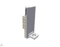
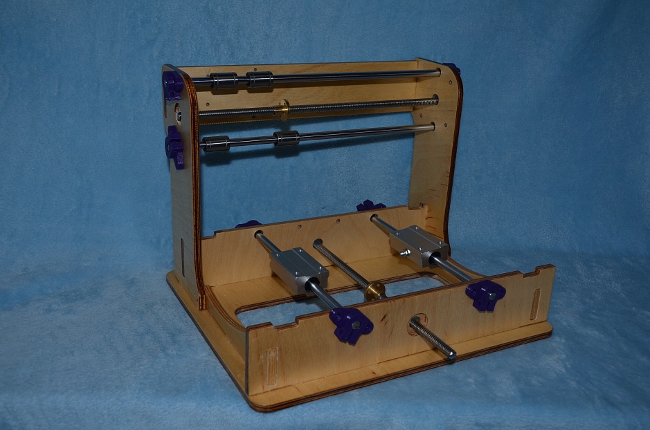
The cross beam, on which the Y-axis rails will be installed, is 510 mm long. In order to unify, we will make it from the same aluminum box 80x40x4 mm. We put the rails directly on the ends of the beam.
A large rectangular hole on the wide edge of the profile will include the axis of the engine with a gear mounted on it. Carriage Z will be placed on the opposite side of the beam. the beam should pass, as it were, through the Y carriage. To do this, we put two identical parts on the ball blocks, made from segments of a standard aluminum channel 60x40x5 mm.
We will carry out the wiring of the toothed belt in the same way as along the X axis, only we will make devices for fastening and tensioning the belt on the corners.
|
|
|

The belt is well protected from chips and dirt. At the bottom of the profile (inside) there will be a cable loop from the Y and Z motors. It remains to put the plugs on the ends of the beam and that's it.
![]()
On the front side (on the side of the carriage Z), the beam has no holes, which is very good, because. this is where the chips fly. As you can see, the beam with the Y carriage turned out to be very simple.
Z
The Z travel is planned to be 90 mm. Why 90? Because 90 is enough for me, but 150 mm can be done. It's not essential.
The Z carriage and everything connected with it is the most busy and time-consuming part of our machine. It is understandable, the drive along the Z axis cannot be done on a belt. Each time the machine is turned off, under the influence of its own weight and the weight of the spindle, the carriage will move down and lose "0". In addition, a significant holding torque is required from the motor, which must compensate not only for the milling force, but also for the weight of the spindle. Only a screw with a pitch of no more than 5 mm (preferably 3 mm) saves the day. So here are the parts to make.
lead screw
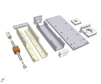
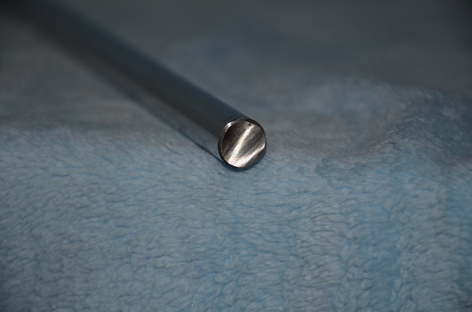
Let's start with the screw. I have already written in detail about lead screws and nuts in the article “Mechanics homemade machine CNC”, I will not repeat. BUT. Is it really necessary in this case on the Z-axis a lead screw with a nut, made according to all the rules of fine mechanics? Unlikely. The machine is designed for flat milling, in fact, it's just a CNC jigsaw - lowered the cutter to the desired depth and - drove to cut it out. A rolled screw will fit here. Yes, why is there a rolled, simple screw with metric thread will do! And a nylon nut will fit! Another thing is if 3D milling is planned, for example, bas-reliefs and medals ... but such a task does not agree well with the belt drive of the remaining axes. So, ANY screw can be used. Any one, but I used a rolled Tr12x2 screw and a bronze nut with backlash compensation. Because today I have it just a jigsaw, and tomorrow I may want to put screws on all the axles. The structure allows.
By the way, the lead screw, the adapter sleeve for the engine and the bearing support rings are the only parts for the manufacture of which we need lathe. Even if you bought a threaded stud on the market, the ends of such a screw must be cut.
The design of the lead screw bearing assembly is described in the above article. It turned out to be successful, so we will do the same in the new machine.
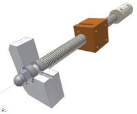
It is not necessary to bore the hole in the wall for the bearings according to the fit, just drill it. The workloads are directed along the axis of the screw, and if the angular contact bearings crawl slightly in the transverse direction, then it's okay, this will practically not affect the accuracy of the axis.
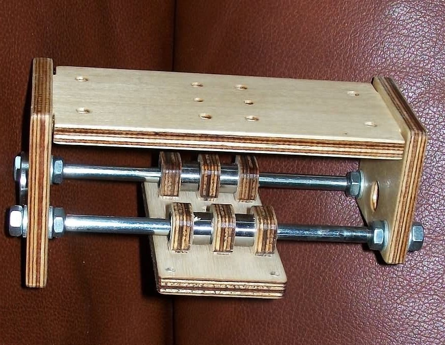
Assembly
We install the lead screw inside the channel base, made of a 60x40x5 mm profile, the same as the one we used for the Y carriage. We screw the rails to the ends of the base.
The attentive reader will say: “Aha! The part on which the engine is mounted is milled!!!”. Not necessary. It can be made from two flat pieces and screwed together. For example, yes.
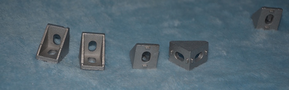
We install the corners on the ball blocks. The corners are made of profile 50x50x5 mm. This is the only available profile made of D16T alloy.
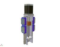
A panel is placed on the corners in front, which, in fact, is the Z carriage. But before that, we will install a jumper that will connect the corners with the running nut.
At first glance, this detail is redundant. The running nut can be fixed directly on the front panel. But in this case, the requirements for the accuracy of manufacturing parts increase significantly, and the installation of the nut will have to be done blindly. Because we have the machine “in haste” and we make it in the kitchen, then in this case such a transition piece can be useful. However, who is confident in himself, may not put it.
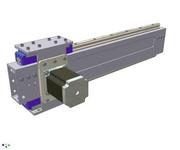
Finishing touch. Install the front panel and spindle bracket.
The bracket can be milled, or maybe just flat. This is how anyone can do it. The lead screw on the Z axis proved to be well protected from direct chips. In general, the Z carriage turned out to be compact, its width is 118 mm. Not a bad result, considering that the main parts are made from standard profiles.
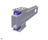
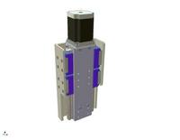
X-Y-Z
Set Z to Y.
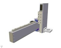
We install the side walls of the portal and the terminal box for cables.

We install the portal on the frame.

Even if you sawed everything crookedly and did not drill holes very accurately, you can still modify the machine, bring it to mind and make it work normally. Because in this design everything is determined by deliberately accurate purchased guides and acceptable geometric accuracy of extruded profiles (parallelism and perpendicularity of the faces). Here, in principle, there are no difficult landings and tight tolerances on linear dimensions. However, it goes without saying that the more accurately you make the details, the better for the machine and for those products that you will cut out on it.
Can i…?
I answer immediately - IT IS POSSIBLE! Everything is possible! Is it only necessary?
“Is it possible to put two ball blocks on the carriage instead of four? It will be almost two times cheaper” - You can! But I put four, and I advise you.
“Is it possible to replace conventional profiles with machine ones? It will be better" - Yes! In a way, it will actually get better. Let's just say, it will be better exactly as much as, for example, a Zhiguli will become better if you put seventeen-inch wheels from a Mercedes on them. But it will be more expensive, that's for sure!
“Is it possible to replace unreliable aluminum profiles with good steel ones to increase strength?” - Can! If you manage to find the right size, and subject to the replacement of ball guides for the 20th size. By the way, the belts need to be taken thicker, and the engines are more powerful, and why is there trifles, it’s better to go straight to the ball screw.
“Is it possible to make such a machine 2x3 meters in size, and to cut 10 mm plywood at a speed of 600 mm / min.?” - Can! Only profiles need to be taken from machine tools and fastened to steel welded frames, and belts should be replaced with gear racks and motors should be taken with gearboxes, and so on.
“Is it possible to use ordinary ball bearings instead of expensive ball guides so that everything drives the same way?” - Can! Will ride! But I still went broke on rails and expensive linear bearings, you can guess why.
“Is it possible to use ours, domestic, furniture, or computer ones instead of imported ball linear guides?” - Can! See the answer to the previous question.
“But I don’t have a drill or a hacksaw for metal. How to be? - Borrow from a neighbor or buy ... it's better to have a ready-made machine right away.
“I want to build the same machine as yours. Could you: give me ready-made drawings, poke your nose where all the components are sold, take me by the hand to my uncle, who will carve the necessary parts, assist in the manufacture, assembly and configuration of the machine, advise, answer questions, and in general, assist in every possible way ? - I could, if you have enough money for all this assistance.
CNC machine It is a numerical control machine.
The CNC machine allows you to quickly get a product designed on a computer, and the CNC machine produces products much faster and more carefully than manually. Precise and highly adaptable, the CNC machine makes it possible to carry out projects that, using hand technology, would be unfeasible or unprofitable.
A good CNC machine should cope with a variety of purposes: milling, laser cutting, drilling, engraving, etc. with minor changes in the configuration of the machine. A CNC machine that is not adapted to the changing and increasing needs of today's production is hardly worth buying. The CNC machine must be multifunctional. However, the cost of a finished CNC machine is quite high. One way out is to create a homemade CNC machine.
Making a homemade CNC machine
The easiest way is to make a CNC machine from MDF board. You will need an MDF board 1.5x1.5 meters and accessories for assembly.
The details of making a CNC machine at home are described in the article CNC (CNC) do-it-yourself MDF machine. This is the easiest machine to make. The article contains a link to a file with drawings, images and nomenclature of fittings and an assembly sequence. The latter is also presented as a video file.
CNC machine made of wood is easy to manufacture, but has a big drawback. It cannot be used to process steel, such a machine can handle aluminum, bronze, wood, plastic or foam.
Another constructive approach is to use aluminum profiles for the manufacture of the CNC machine. This approach can be found in the article CNC machine "in haste". Such a machine looks more functional, but its manufacture is much more difficult. When replacing aluminum profiles with steel ones, it is possible to achieve the processing of steel billets.
There is also a designer of the CNC machine "Kulibin". The designer includes all the details for assembling the CNC machine. By combining the guides in different ways, you can get various designs CNC machines. The designer can be purchased through the website's online store.
Places of communication CNC do-it-yourselfers
Most often homemade cnc machines are used in aircraft modeling. And this is no coincidence. The aircraft model does not forgive negligence of control and the slightest distraction from control is fraught with an unplanned meeting of the model with the ground.
In this case, usually the wing panels and the nose of the fuselage of an aircraft model break. They are easy to restore, and then the CNC machine comes to the rescue. Cutting 40 wing ribs and 20 fuselage parts by hand is simply tedious. And breakdowns during training (and after it) happen almost weekly.
Therefore, it is no coincidence that one of the places of communication is the forum of RC-Design modellers.
On the website of the designer Kulibin, you can see articles about various machines constructor based.
On VRI-cnc, you can download both CNC machine drawings and electronic filling diagrams.
An article on the topic of self-building a small machine for woodworking (engraving, milling, drilling) with CNC, also suitable for others soft materials, for example, plastic. Good for milling printed circuit boards and similar work. This and the following articles describe common components and techniques for assembling not only CNC machines, but also 3D printers, engravers and similar equipment. There is a lot of information, a lot of links and photos, the project is open, advice and criticism (on the case) is welcome.
Here are some photos appearance assembled CNC2418 machine from lots of sellers from Ali

Examples of lots with Ali with a laser and an ER11 collet (DZT store, Jack's store, IRouter store).
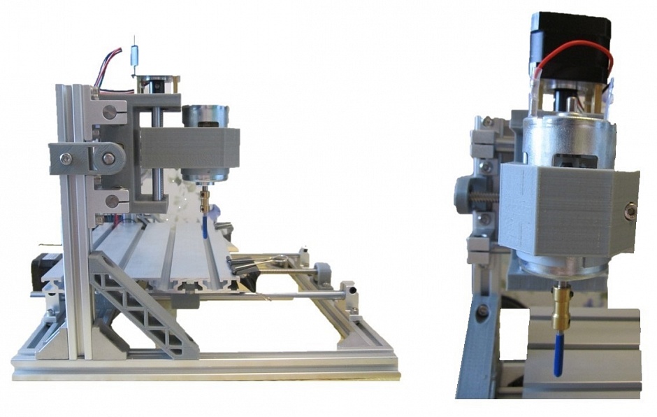
So, I’ll tell you about a fairly popular Chinese machine under the simple name CNC2418, which means a working area of 24 mm by 18 mm. As a spindle, it has a simple (collector) revving DC motor type 775. It is controlled via GRBL compatible programs, but first things first.
As a rule, it is sold in the region of $250 (from $170 to $300) in different configurations. There is a version with different spindles (different variations of the 775th engine), with different collets (from simple for drills to ER11), can be equipped with a laser module. Usually sellers invest consumables, cutter bits and more.
Characteristics of the machine 2418:
- Working field - 240 mm x 180 mm x45 mm
- Frame (bed) size - 260 mm x180 mm (aluminum profile)
- Overall size - 330x340x240
- Stepper motors: 3pcs Nema17 1.3A 0.25Nm
- Spindle: Diameter 45mm, model 775, 24V: 7000 r/min
- The maximum shank diameter of the cutter depends on the installed collet
- Power: 24V 5.6A
Here is a photo of the average $250 kit (including the laser engraving kit)

There is usually a choice of collets in the lot: a simple "drill" or an ER11 type collet. In lots more expensive there are both options plus milling cutters.

Seriously speaking, the market value of such assembly kits is greatly inflated. I'm not ready to pay under $300 for a similar set. But to assemble it with your own hands is three times cheaper - please! Next, I will give a selection of components from Chinese stores, on the basis of which you can safely assemble a similar machine or a machine with a larger / smaller working field.
For assembly, you will need to buy a set of guides: rails or polished shafts; lead screws (most often T8, since belts of the GT2-6 type can be installed in laser engravers, their use in a router is not desirable), Nema17 motors, a spindle (most often a DC motor of the RS775 type or more powerful) and various small things such as bearings, calipers , hardware.
The issue of electronics is separate: someone uses Arduino Nano / Uno + CNC Shield boards, someone Mega + Ramps, there are options for more serious kits for Mach3.
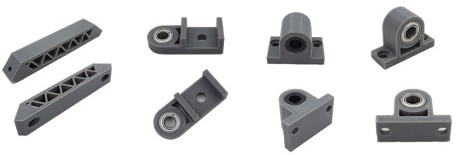
Drawing your attention to the fact that the original kit contains 3D printed components.
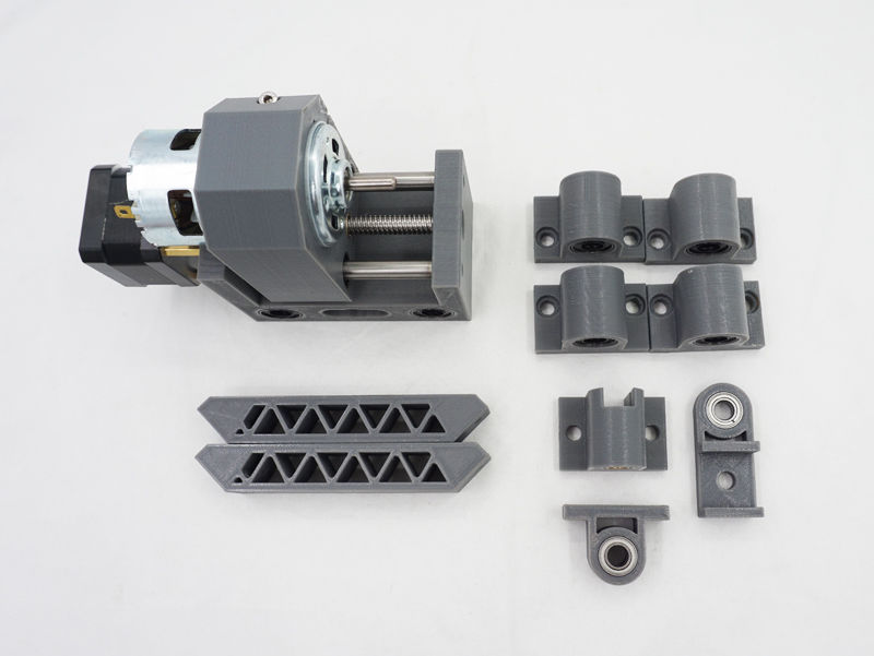
The use of such plastic parts is clearly visible in user photos from the Internet, and in lots from sellers
The printed kit includes spacer-corner (2 pcs), X screw holder, Y screw holder, LM8UU bearing holders (or rather their imitations) 4 pcs, T8 nut holder.
Separately, I will highlight the assembly of the spindle holder, at the same time the carriage in XY.
It also comes assembled with the engine installed.
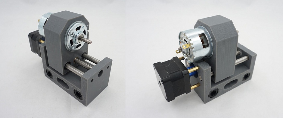
Inside you can see pressed LM8UU bearings and somewhere a T8 nut. The shafts are drilled from the end and fixed at the ends. At the same time they serve as an additional support for the structure.
I give links to the kit from banguud, because I'm tired of buying 1 lot from different sellers with Ali and waiting for a bunch of parcels coming to different time. Prices comparable to Ali, somewhere cheaper, somewhere it’s more convenient to use points, somewhere to wait for a promotion or coupon. As a result, I received one large parcel with a kit. I also cite keywords for self-search, if you need to find something similar on Ali or Tao.
Now in order. Received a parcel of various kits for machine tool mechanics.
![]()
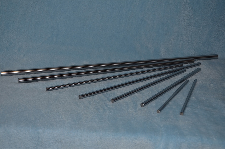
Polished guide shafts.
Linear Shaft (Rod). Still found optical axis(polished axle). There are 5-6-8-10-12-16-20 mm. The current diameter is 8 mm. For 16-20mm it is better to use round rails like SBR16 or SBR20 as they have support. Shafts of different diameters are used, for example, in the Ultimaker printer (6-8-10 mm). By the way, 12mm shafts can be useful for the Z-axis of the ZAV 3D printer and the like.
In the photo 6 mm, 8 mm, 12 mm.
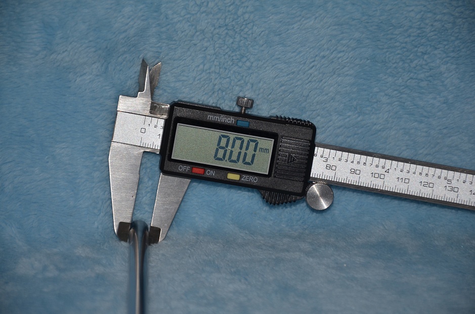
Shafts 8 mm. I took a part in size (they are chamfered), I cut a part myself

There is a large lot with a choice of shafts from 5 mm to 12 mm and lengths of 300-600 mm

Individual lots are slightly cheaper. I try to take the length either in size or much more in order to independently cut 2-3 pieces of the desired size from one shaft.
Here is a cut with a miter saw. It is desirable then to clean, chamfer.
Shaft 8x600
Shaft 8 mm with lengths 300...500 mm
Shaft 8 mm with lengths 100…350 mm
Comfortable when sized. Yes, and from time to time they make promotions for different lots, if you don’t rush to assemble the machine, you can save money.
Shaft 6x400
Shaft 6x300
Shaft 6x500
Shaft 6x600


6mm shafts can be used in small laser engravers, delta printers, Z axis desktop CNC machines. For example, a 6x300 shaft, sawn in half, went to the "head" of the Z axis of a small router.
Shafts on 12 mm. Took for ZAV 3D.
Shaft 12x500
Will be installed in the ZAV 3D case
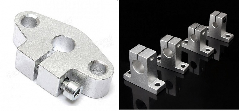
There are several mounting options for rails. The easiest is to cut the threads at the ends and lock them. Flanges type SHF08 or calipers SK8 can be installed. In this case, the length is increased by 2 cm for each guide (one flange covers 1 cm of the shaft).
I printed it myself, I won't say that it's a big difference, but the savings are about $12. Here is a link to the lot for fitting SHF08 normal metal flanges, not plastic ones. More a good option fastening not with flanges, but with calipers, directly on the 2020 profile. This is a SH08 (SF08?) caliper.
There is also a “Chinese” mounting option, when a hole is drilled in the center of the shaft and cut internal thread M3. In this case, the installation of such guides is as easy as possible.
Flanged calipers for mounting shafts from SHF8 to SHF20
Flange SHF8
Caliper SK8
Another SK8 support for profile shafts
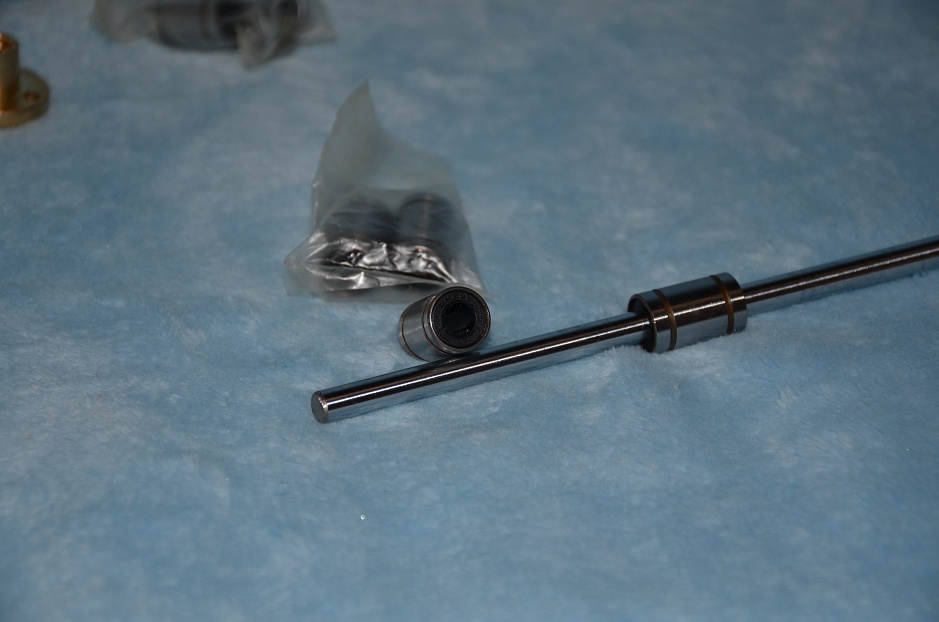
Shaft bearings
Lot with a choice of size short linear bearings LMххUU for 6/8/10 mm
Keywords: Bearing LMххLUU (for xx mm, long), LMххUU (for xx mm, short), in the body, respectively: SC8LUU and SC08UU.
Elongated lot with a choice of type SCSxxLUU from 8 to 20 mm.
Also extended by 8 mm
Bearings in SC8UU housing
For 6 mm LM6LUU extended and regular LM6UU
Here is a photo of an electronics bench machine with 8mm shafts, LM08LUU and SC08UU bearings
Here are interesting kits-sets of axles with guides and bearings
500 mm with extended bearings
The same, plus a T8 screw with a caliper for 200mm, 300mm and 400mm

Lead screw T8 ( Lead Screw T8, screw T8 Nut) is a screw with multiple threads. It is better to take immediately with a nut.

If sawing, then in addition it will be necessary to buy more brass nuts
At 100 mm
At 200 mm
At 250 mm
At 400 mm
Lot with a choice of T8 from 100 to 600 mm with a special nut
I usually take more, plus one nut. I cut to size, the rest goes somewhere else

Caliper flange KP08 for fastening the T8 screw to the Mount Bearing KP08 profile Assembly will also require a structural profile, 3D printed parts (holders, corners, etc., links at the end of the article), as well as electronics.

Profile accessories:
corners 2020 Corner Bracket.
To assemble a machine type 2418, a minimum of 16 pieces will be required. Take with a margin)))
There are options for reinforcement plates, it would also be nice to install them at the main corners and on the portal (total 6-8 pieces).
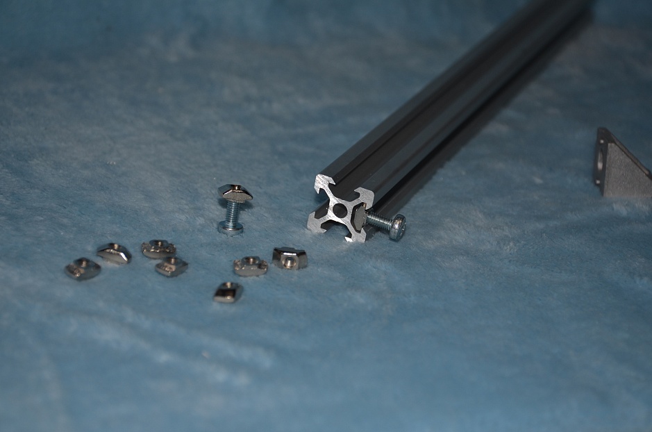
And here is the 2020 profile itself.
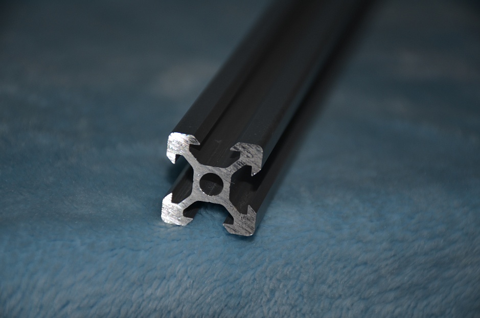

Since I started talking about the profile, I will tell you in detail about the purchase and cutting of the profile from the Soberizavod.
This is a structural aluminum profile from Soberizavod. This is probably the most cheap option, since a profile from China will cost more, and there is a limit on the maximum length of parcels in Chinese mail (500mm).
I bought a 2020 profile kit cut to size for the CNC2418.
There are two options - uncoated profile (cheaper) and coated (anodized). The difference in cost is small, I recommend coated, especially if used as roller guides.

Choose desired type profile 2020, then enter "cut to size". Otherwise, you can buy one piece (whip) for 4 meters. When calculating, keep in mind that the cost of one cut can be different, depending on the profile. And that 4 mm is laid on the cut.
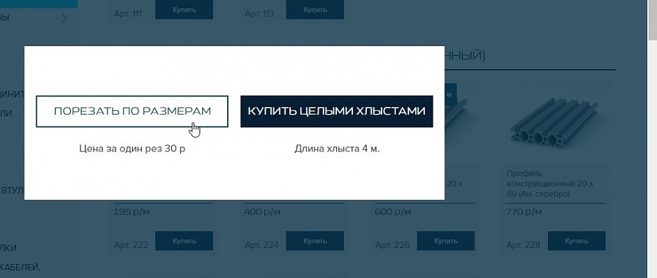
Enter the dimensions of the segments. I made machine 2418 a little larger, these are seven pieces of 260 mm and two vertical pieces of 300 mm. Vertical can be made smaller. If you need a longer machine, then two longitudinal sections are larger, for example, 350 mm, transverse ones are also 260 mm each (5 pcs).


Mixed Personality Disorder: Causes, Symptoms, Types and Treatments
GTA 4 control settings
FAQ on Smuggling in GTA Online
LSPDFR - welcome to the police
The huge map of Grand Theft Auto San Andreas and its secrets