Methods of cutting with a consumable electrode.
arc cutting is one of the types of separation cutting. It is based on the melting of metal from the cutting zone by the heat of an electric arc excited between the electrode and the metal being cut. This method is widely used in construction and installation works for rough cutting of metal. Cutting is done with steel electrodes quality coating, but more refractory than for welding. Such a coating provides, during cutting, the formation of a small visor that covers the arc zone. The visor protects the electrode from a short circuit to the metal being cut, and also contributes to a more concentrated heating of the metal and allows cutting more productively. As a coating, a mixture containing 70% manganese ore and 30% liquid glass. The coating thickness is 1…1.5 mm. Coated electrodes are also successfully used TsM-7 and TsM-7s. Electrodes diameter 4..6 mm are the most recommended. The cutting current is selected within 50…60 A on the 1 mm electrode diameter. The arc power source can be welding generators or welding transformers. Arc cutting is used to cut metals with a thickness of not more than 30 mm; productivity is low - with the thickness of the metal being cut 15 mm cutting speed does not exceed 120…150 mm/min. The electrode consumption is 1.0…1.5 kg on the 1m cut metal.
Inert gas welding is a welding method that is faster than coated arc welding for the following reasons. Weld metal obtained by inert gas welding has a low hydrogen content, which is very beneficial for steels with hardening properties. Because deep penetration is possible with inert gas welding, small fillet welds can be made and root penetration is smoother compared to coated arc welding. It is very suitable for use in semi-automatic and fully automatic welding systems.
Oxy-arc cutting differs from the arc one in that a jet of pure oxygen is supplied to the section of the metal surface heated to melting. Oxygen burns through the metal of the cutting area and blows out the formed oxides and molten metal from the cut cavity. During the combustion of the metal, additional heat is released, which speeds up the process of melting and cutting the metal. This method is used to make short cuts in various building structures.
Inert gas welding equipment is more complex, more expensive and more difficult to transport than electrical equipment. arc welding coated. Since the inert gas welding torch must be close to the workpiece, it is more difficult to weld in hard-to-reach places compared to coated arc welding. Welds made using inert gas welding on steels with hardening properties are more prone to cracking because there is no slag layer that reduces the cooling rate welding metal, as is the case with coated arc welding.
VNIIavtogenmash has developed a method for manual oxygen-arc cutting with a cutter of the type RGD. With this method, the cutter right hand holds the electrode holder, and in the left - the cutter. Having excited the arc and heated the metal to melting, the cutter presses the handle of the oxygen valve and directs a jet of oxygen to the heated metal, then the arc and the cutter move along the cut line. The electrodes are steel rods with a diameter 4…5 mm coated TsM-7 , OMM-5 , OZS-Z etc. The current, depending on the diameter of the electrode, is 160…250 A. This method can cut metal with a thickness up to 50 mm. metal thickness 10…20 mm cut with an electrode diameter 4 mm with speed 450…550 mm/min. The oxygen consumption is 100…160 l/min. Carbon and low alloy steels 50 mm cut with an electrode diameter 5 mm with speed 200 mm/min with oxygen consumption up to 400 l/min .
Inert gas welding requires additional airflow shielding to send gas shielding out of the welding area. Therefore, it is not suitable for arc welding with outdoor electrodes. Flux-cored arc welding is an arc welding method where the heat required for welding is generated by an arc formed between a flux-cored wire electrode and the workpiece. Protection of the arc and welding area is provided by gases resulting from the combustion and separation of the elemental substance in the flux-cored wire or by using an external shielding gas, as is the case with inert gas welding.
An important advantage of oxy-arc cutting is the ability to combine cutting with welding work during the installation of various building structures.
Methods of cutting with a non-consumable electrode.
The following types of arc cutting with a non-consumable electrode are used: separation cutting with a non-consumable electrode, air-arc cutting and plasma-arc cutting .
The self-closing welding process is similar to gas shielding in the coated electrode welding method. The coating material on coated electrodes causes flat rod electrodes and length limitations. However, in flux-cored wires, this coating material is in the form of a wire wrapped around a roller, since the tubular wire is inside the electrode and can be fed into the continuous welding zone.
This welding method can be applied to both semi-automatic and fully automatic welding systems. A disadvantage of flux-cored welding is that a slag layer, which is similar to that of coated arc welding but slightly thinner, is formed on the weld. However, many types of flux-cored wire electrodes that do not require slag removal or generate slag are manufactured today.
Separation cutting produced non-consumable electrode: carbon, graphite or tungsten. Carbon and graphite electrodes diameter 12…25 mm allow cutting metal up to 100 mm. Cutting is carried out with direct current of direct polarity. The current depending on the diameter of the electrode is 40… 1000 A. Carbon electrodes in the process of cutting carburize the edges of the cut and this makes subsequent machining difficult. Graphite electrodes give a cleaner cut, last longer and allow higher current densities.
The gas must be able to completely shield the area to be welded, otherwise very little air infiltration causes errors in the weld metal. Since the electrode is not wasted, welding is carried out by melting the base metal or using additional welding metal. Welding can be done in any position and is especially suitable for welding thin materials. It provides highly aggressive and non-porous welds in root pass welding. Since the heat input is concentrated on the weld area, the workpiece is slightly deformed.
Air arc cutting used for both separation and surface cutting. With this method, an arc is excited between a non-consumable electrode and the metal being cut. The heat of the arc melts the metal of the cutting area, and the jet of compressed air continuously removes it from the cut cavity.
Rice. one
For air-arc cutting of mild steel and stainless steel up to 20 mm use a universal cutter RVD-4A-66(Fig. 1: 1 - electrode , 2 -head , 3 - push lever , 4 - frame , 5 - cable-hose ). It has replaceable carbon electrodes with a diameter 6…12 mm. current reaches 400 A, and in the short-term forced mode - 500 A. The air pressure is 0.4…0.6 MPa. Air flow at pressure 0.5 MPa does not exceed 20 m3/h. Weight of cutter - 1 kg. The cutting process proceeds steadily when the torch is powered by direct current of reverse polarity. With direct current of direct polarity and with alternating current the process is unstable, productivity is low with poor quality of the cut surface. The cutting performance depends on the current. At current 200 A per 1 hour work can be deleted. up to 7 kg low carbon steel, at current 300 A- before 10 kg, and when 500 A- near 20 kg. In addition, with increasing current, the specific power consumption decreases with 3 kWh/kg at current 300 A before 2 kWh/kg at 500 A .
It also provides a smooth weld and no seam removal is required. This is not an economical method for welding thick materials. Dip welding is an arc welding method where the heat needed for welding is generated by an arc formed between a draining electrode and the workpiece. The arc welding powder layer as well as the weld metal and the base metal close to the weld are protected by the molten welding powder. In dip welding, electricity passes through an arc and a weld pool of molten metal and molten slag.
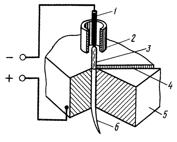
Rice. 2
Plasma arc cutting is a progressive high-performance way of cutting metals. It is carried out by deep penetration of the metal with a compressed arc in the cutting zone and the removal of particles of molten metal by a gas stream. On fig. 2 is a diagram of the process. The arc is excited and burns between the tungsten electrode 1 and cut metal 5 . Current direct direct polarity. The electrode is inside a cooled copper mouthpiece 2 . A plasma-forming gas is supplied under pressure into the mouthpiece channel, the jet of which compresses the arc column 3 . Under the action of the arc, the gas is heated to a high temperature, more 10 000°C, forming a plasma. Plasma jet 6 , having a high temperature and a high flow rate, it melts the metal along the cut line 4 and blows molten metal out of the cut cavity.
The arc thermal electrode forms a weld pool, which fills the welding bend by melting the melting powder and the base metal. The welding powder, acting as a protective element, also reacts with the weld pool and deoxidizes the weld metal. Welding powders used for welding alloy steels may contain alloy elements that compensate for the chemical composition of the weld metal. Dip welding is an automatic welding method. In some underwater arc welding applications, two or more electrodes may be simultaneously fed into the welding bend.
Plasma arc cutting can be used for cutting alloyed and carbon steels, cast iron, non-ferrous metals and their alloys. It is most rational and economical to use it when cutting high-alloy steels, non-ferrous metals and their alloys. The electrodes are made from lanthanated tungsten VL-15 or thoriated tungsten BT-15 .
The electrodes may be fed into the weld pool in a double arc, or may be sequentially fed through a distance sufficient to individually harden the weld pools, and thus a high welding speed and a high metal accumulation rate can be achieved.
It is a welding method with high welding speed and high metal accumulation rate, which can be used for welding flat and cylindrical parts, pipes of any thickness and size, and welding seams. It provides perfect and mechanically elastic welds. Because there is no spatter and the arc lights are invisible, the level of protection needed to protect the welding operator is less. It is possible to weld welding bend angles contrary to other methods. Dip welding can be carried out both inside and outside.
Plasma-forming gases are pure argon of the highest grade, technical nitrogen 1 th grade, mixture of argon with commercial hydrogen, air.
Arc power sources are single-station welding converters PSYU-500 and rectifiers VKS-500. To provide increased open circuit voltage, series connection is used. 2…3 converters per arc. Special power supplies for the plasma arc are also used. IPG-500-1 and rectifiers VDG-502 .
Dip welding powders are susceptible to moisture from the air, which causes pores during welding. The base metal must be flat and smooth, and the base metal must be free of oil, rust or other impurities in order to obtain high quality welds. The slag must be removed from the weld and this can be difficult in some cases. In multi-pass welding, slag should be removed after each pass to prevent slag residue. The dip welding method is not suitable for materials with a thickness of less than 5 mm, as it may cause oxidation.
The thickness of the metal being cut is largely dependent on the stress. For example, at operating voltage 75 V the maximum cutting thickness of aluminum reaches 25 mm, and at voltage 250 V - 300 mm. The current is 150…800 A .
Installations in which air serves as the plasma-forming gas are widely used. These include setting UPR-201 designed for manual plasma cutting metal thickness up to 40 mm at a temperature environment from +40 to -40°C. The installation consists of a power source, cutting process control equipment and a plasma torch. Maximum operating current - 250 A. Air pressure - 0.5.-.0.8 MPa. Air consumption - 70…100 m3/h .
This method is suitable for butt welding and fillet welds in flat and horizontal spaces, except in some applications. Various welding processes work for various types metals. Each type of welding process has its advantages and disadvantages. A team of tractor welding experts have developed these handy charts to help you determine what type of metal you need to complete your welding project.
What type of metal do you want to weld? What thickness of metal do you want to cut with plasma cutting? You will need a plasma cutter powerful enough to cut the desired metal and thickness. What are your welding skills? Some types of welding require more skill than others.
avov in construction and installation conditions use an assembly mobile post KPM-1 mounted on a single axle trailer GAPZ-755A. The equipment consists of a welding rectifier VKS-500-1, compressor, two ballast rheostats RB-300-1, burners GDS-150, cutter RDP-2, cylinders with argon and nitrogen. Ventilation in cutting mode - forced. All post equipment is protected from atmospheric precipitation by a metal casing. The post performs welding of metal thickness up to 2.5 mm and cutting copper (thick up to 20 mm), become ( up to 40 mm) and aluminum ( up to 50 mm). Mass of mobile post - 1500 kg .
Decide where and under what conditions you will weld. For example, a process such as stick or flux powder welding can be used in windy, outdoor conditions, while powder welding is good for out of position work. Keep the following guidelines in mind.
- What materials can be welded with a welding machine?
- It is capable of welding thinner materials.
- It reduces spatter.
- No welding slag to reduce cleaning.
- It is universal, especially 115 volt models.
- It can weld stainless and aluminum wires.
Several methods have been developed and used for cutting metals (steel, cast iron, non-ferrous metals) with an electric arc.
1. Arc cutting of metals is carried out using:
1) metal consumable electrode. This method consists in the fact that the metal is melted using a higher current value (30-40% more than in arc welding).
- It's easier to work.
- You can stick thinner materials.
- You can use strong and flux-cored wire.
- It is easier to weld aluminum.
- Can be used with golden guns.
It also uses electricity rather than oxygen and acetylene. The plasma cuts through all electrically conductive materials, where oxyacetylene is limited to ferrous materials. Gas welding is an alloy where the steel welding rod is actually melted with the steel base metal to become one piece of metal. Gas brazing is actually adhesion, as the final bond between two separate pieces of metal. After the base metal is heated, a brass filler rod is applied over the base metal and the two parts are adhered or glued. Clients verify the ownership of trading cylinders to participate in the exchange by signing the Owner Confirmation Form. In recent years, environmental and quality issues have taken center stage in the welding industry.
An electric arc is excited on the upper edge at the beginning of the cut and gradually moves it down along the edge (Fig. 83).
Drops of liquid metal are pushed out by the visor of the electrode coating. In addition, it isolates the electrode, preventing it from shorting to the metal.
Cutting in this way has a number of disadvantages, in particular, it has low productivity and gives a poor-quality cut. The modes under which cutting is carried out are presented in table. 32;
This increased focus on safety and health is often accompanied by a rethinking of how certain tasks are performed, such as cutting and gouging metal. Tailoring has been a requirement for many years in several industries and applications - this is one way to scrutinize. Especially when maintenance and repair, the ability to wipe or groove metal is critical and deserves due attention.
Two of the most common metal gouging methods are plasma gouging and air carbon arc. During maintenance and repair, operators must remove any of the following: welds or metal to replace a worn or defective part; worn hard deposits so that the overlay can be reapplied; defects in the weld, so the part can be rewound. If both sides of the slab need to be welded, back seams for sound metal may also be required.
2) carbon electrode. This method is used when cutting cast iron, non-ferrous metals and steel when there is no need to strictly observe all dimensions, and the quality and width of the cut do not play any role. In this case, the cutting is carried out by melting the metal along the dividing line. Cutting is carried out at direct or alternating current from top to bottom, placing the melted surface at a slight angle to the horizontal plane in order to facilitate the flow of liquid metal. Cutting modes are presented in table. 33.
The blade is also used in the foundry business to remove fins, risers and defects from castings. In the usual ways gouging are mechanical methods such as grinding, hand milling, routing and trimming; oxy-dust gouging, which can only be used on carbon steels; and air carbon arc.
Young scientist Robert Gage discovered that by forcing a gaseous tungsten arc through a small hole, in a process similar to focusing a beam of light through a lens, the temperature and intensity of the arc could be increased. By passing a rather high flow of gas through this focused arc, he could cut the metal.
|
Table 32
|
3) non-consumable tungsten electrode in argon. This cutting method is rarely used, mainly when working with alloyed steels and non-ferrous metals. Its essence lies in the fact that a current is applied to the electrode, the value of which exceeds that during welding by 20-30%, and the metal is melted through.
2. Oxy-arc cutting (Fig. 84). In this case, the metal is melted by an electric arc, which is excited between the product and a rod electrode made of low carbon or stainless steel ( outside diameter- 5-7 mm, internal - 1-3.5 mm), after which it burns out in a stream of oxygen supplied from the hole of the tube and oxidizes the metal, and is blown out. Oxy-arc cutting is used mainly in underwater work.
3. During air-arc cutting (Fig. 85), the metal is melted by an electric arc excited between the product and a carbon electrode (plate or round), and removed with a jet of compressed air.
The cutting process is carried out using direct current of reverse polarity (with direct polarity, the heating zone is wider, which creates difficulties when removing metal) or alternating current.
The current value is determined by the formula:
where I - current;
K - coefficient 46-48 and 60-62 A/mm for carbon and graphite electrodes, respectively;
d is the diameter of the electrode.
For this method, special cutters are used, which are of two types and therefore require different cutting modes:
Cutting torches with a consistent arrangement of the jet of air;
Cutters with an annular air jet.
Air-arc cutting is divided into two types, which correspond to different modes (Tables 34 and 35):
Surface gouging used for cutting defects formed in the metal or weld, hemming the root weld and chamfering;
Separating cutting used in the processing of stainless steel and non-ferrous metals.
4. Plasma-arc cutting, the essence of which is that the metal is melted by a powerful arc discharge, concentrated on a small area of the surface of the metal being cut, and removed from the cut zone by a high-speed gas jet. The cold gas entering the burner flows around the tungsten electrode and turns into plasma in the discharge zone, which then flows out through a small hole in the copper nozzle in the form of a brightly luminous jet at a high speed and a temperature reaching 30,000 ° C (or more). circuit diagram plasma-arc cutting is shown in fig. 86.
Plasma cutting can be done with independent or dependent arc. In this case, one speaks of a plasma arc of direct or indirect action.
The cutting modes that you can focus on are clearly presented in Table. 36.
5. Arc cutting under water. In a liquid medium, for example, in water, it is possible to create a powerful arc discharge, which, having a high temperature and a significant specific thermal power, can evaporate and dissociate the liquid. The arc discharge accompanies the formation of pa-
ditch and gases, which will enclose the welding arc in a gas shell, i.e., in fact, the arc will be in a gaseous environment.
A stable welding arc from standard power sources will give carbon and metal electrodes. For underwater cutting, they must be covered with a thick waterproof (paraffin-soaked) coating, which, when cooled from the outside by water, will melt more slowly than the electrode rod. As a result, a small bowl-shaped visor is formed at its end, due to which the stability of the gas shell and the burning of the arc will be ensured.
The current value is set at the rate of 60-70 A per 1 mm of the electrode diameter.
The described cutting method is used in the repair of ships, etc.


How to cook ham in the oven at home
Pain in the lower abdomen during pregnancy, reasons for what to do Can the lower abdomen hurt if pregnant
Protein for muscle gain
The best vitamins for men according to customer reviews
How to lose weight on a vegan diet?