arc cutting metals or metal cutting by welding , is the melting of the metal in the place where it is necessary to make a cut, followed by its removal due to its own weight and due to the pressure of the arc.
Metal cutting by welding is most often performed manually, as a rule, either metal electrodes or carbon electrodes are used to cut metal with an arc.
Applies arc cutting of metals mainly for cutting cast iron, for cutting non-ferrous metals, for cutting high-alloy steels and other various alloys.
The quality of cutting metal with an electrode is usually very low, the edges of the metal are not even, and the abundance of slag also leaves much to be desired, although it is worth noting that in many respects all these properties also depend on the experience of the welder who performs arc cutting of metal.
It is worth noting that no matter how experienced the welder who cuts the metal by welding, before welding the parts at the cut point, the surfaces will need to be subjected to a thorough cleaning.
As for the productivity of metal cutting by welding, it is low.
One of the most important advantages of metal arc cutting is that metal cutting by welding can be carried out almost anywhere where there is an opportunity for arc welding.
This type of metal cutting does not require special equipment.
The advantages of arc cutting of metals include the ability to cut in all spatial positions, it is this versatility that allows cutting low-alloy and carbon steels in installation conditions and in hard-to-reach places.
Separation cutting of metal by welding
For split arc cutting , the product to be cut is set in such a way that during the cutting process, the molten metal has more favorable conditions for flowing out.
If it is necessary to perform a vertical cut, then such a cut should be made from top to bottom, when cutting metal in this position, the molten metal will not clog the already cut places and welding will be much easier.
Arc separation cutting of metal as a rule, they start from the edge of the sheet (from the edge), or from the middle of the sheet, depending on what kind of cut needs to be made.
If it is necessary to make a cut from the middle of the sheet, then in this case, a hole is first cut out, after which the electrode, which is used to carry out the cut, must be tilted so that the location of the crater is on the edge of the cut, after which the melting begins.
It happens that the width of the sheet to be cut is smaller in relation to the welding electrode, which is used for cutting, in this case, it is necessary to turn the electrode perpendicular to the sheet being cut, and without any hesitation, simply lead it along the cut.
Arc cutting of metal. superficial
If necessary, perform surface arc cutting of metal
, the electrode must be tilted to the surface so that its angle is from 5 to 20 degrees, and then begin to move it, partially, into the cavity formed by immersing the end of the welding electrode. 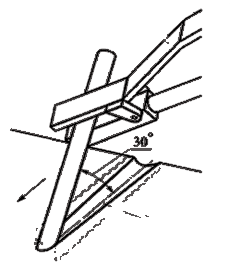
In order to melt wide grooves, it is necessary to use transverse vibrations of the welding electrode in a vertical position.
It is worth noting that the width of the groove depends on how tilted the electrode is and how fast it moves.
Therefore, it is necessary to catch the required pace and set the desired angle of the electrode, and then simply stick to the established position.
Deeper grooves are usually performed in several passes.
If nessesary arc cutting to cut a hole in the metal, you need to install the electrode perpendicular to the metal, and then excite an arc, which will possibly be even longer.
Arc cutting of metal with a metal electrode
When cutting metal by welding , or rather welding metal electrodes, usually use electrodes that have a thick coating, in other words, welding electrodes or electrodes for welding.
The current must be set depending on what brand of welding electrode is being cut.
Worth paying attention that the metal cutting speed is affected by three factors that must be taken into account, this is the diameter of the electrode that is used for cutting, the thickness of the metal and, of course, the magnitude of the welding current that is used for cutting.
Actually, it is not difficult to guess that the thicker the metal to be cut by welding, the lower the speed of the cutting process.
In order to perform arc cutting of metal with a graphite or carbon electrode, it is necessary to use a direct current, of direct polarity, due to the fact that in this case, much more heat is released on the product to be cut.
Do not carburize the edges of the metal that will be cut, as this can greatly complicate their subsequent mechanical cutting.
It is also worth noting that when cutting metal with carbon or graphite electrodes, the width of the resulting cut will be greater than when cutting with a conventional metal electrode.
Arc cutting holes in metal
Cut a hole in the metal with a welding electrode easier than it might seem at first glance, first you need to cut a small hole, and then, leading the electrode along the edges of this small hole, gradually expand it to the required diameter.
When cutting metal by welding, special attention should be paid to spatter and slag, since during arc cutting, there is a very high probability that hot metal particles (slag, molten metal, harmful gases) get on the body or clothing of the person who is cutting.
It is important to remember that no one canceled safety precautions.
Lap joints with a metal thickness of 0.8–2 mm are usually welded by weight, sometimes on a copper lining. Welding speed can be increased subject to quality assembly.
When welding copper, the welding arc zone is protected with nitrogen. Nitrogen-arc welding is carried out with carbon or graphite rods, since the use of tungsten rods is economically unprofitable (low-melting compounds (tungsten nitrides) are formed on their surface, which leads to an increase in tungsten consumption), with a direct current of direct polarity. The diameter of the carbon electrode is 6–8 mm at a current value of 150–500 AV; nitrogen consumption - 3-10 l / min; arc voltage - 22-30 V. To fix the rods, the torch must be equipped with replaceable tips.
Arc cutting technology
Several methods have been developed and used for cutting metals (steel, cast iron, non-ferrous metals) with an electric arc.
1. Arc cutting of metals is carried out using:
1) metal consumable electrode. This method consists in the fact that the metal is melted using a higher current value (30–40% more than in arc welding).
An electric arc is excited on the upper edge at the beginning of the cut and gradually moves it down along the edge (Fig. 83).
Rice. 83. Scheme of cutting with a metal consumable electrode
Drops of liquid metal are pushed out by the visor of the electrode coating. In addition, it isolates the electrode, preventing it from shorting to the metal.
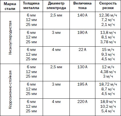
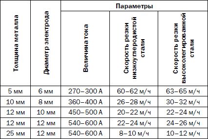
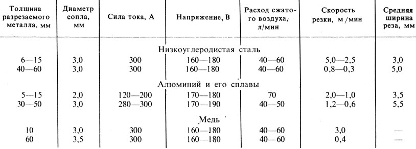
Cutting in this way has a number of disadvantages, in particular, it has low productivity and gives a poor-quality cut. The modes under which cutting is carried out are presented in table. 32;
Table 32
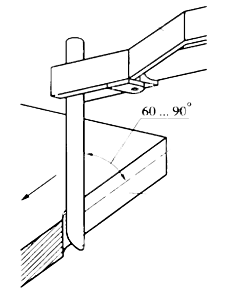
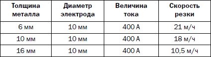
2) carbon electrode. This method is used when cutting cast iron, non-ferrous metals and steel when there is no need to strictly observe all dimensions, and the quality and width of the cut do not play any role. In this case, the cutting is carried out by melting the metal along the dividing line. Cutting is carried out at a constant or alternating current from top to bottom, placing the surface to be melted at a slight angle to the horizontal plane in order to facilitate the flow of liquid metal. Cutting modes are presented in table. 33.
Table 33
3) non-consumable tungsten electrode in argon. This cutting method is rarely used, mainly when working with alloyed steels and non-ferrous metals. Its essence lies in the fact that a current is applied to the electrode, the value of which exceeds that during welding by 20–30%, and the metal is melted through.
2. Oxy-arc cutting (Fig. 84). In this case, the metal is melted by an electric arc, which is excited between the product and a rod electrode made of low carbon or stainless steel ( outside diameter- 5-7 mm, internal - 1-3.5 mm), after which it burns out in a jet of oxygen supplied from the hole of the tube and oxidizes the metal, and is blown out. Oxy-arc cutting is used mainly in underwater work.
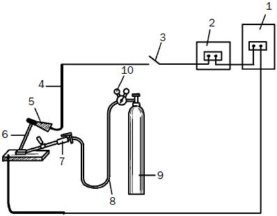
Rice. 84. Scheme of the equipment of the post for oxygen-arc cutting: 1 - power source (transformer); 2 - regulator; 3 - knife switch; 4 - cable; 5 – electric holder; 6 - electrode; 7 - cutter RGD-1-56; 8 - oxygen hose; 9 - oxygen cylinder; 10 - reducer
3. During air-arc cutting (Fig. 85), the metal is melted by an electric arc excited between the product and a carbon electrode (plate or round), and removed with a jet of compressed air.
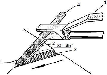
Rice. 85. Scheme for the implementation of air-arc cutting: 1 - cutter; 2 - air jet; 3 - groove; 4 - electrode
The cutting process is carried out using direct current of reverse polarity (with direct polarity, the heating zone is wider, which creates difficulties when removing metal) or alternating current.
Table 35
4. Plasma-arc cutting, the essence of which is that the metal is melted by a powerful arc discharge, concentrated on a small area of the surface of the metal being cut, and removed from the cut zone by a high-speed gas jet. The cold gas entering the burner flows around the tungsten electrode and turns into plasma in the discharge zone, which then flows out through a small hole in the copper nozzle in the form of a brightly luminous jet at a high speed and a temperature reaching 30,000 °C (or more). circuit diagram plasma-arc cutting is shown in fig. 86.
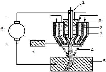
Rice. 86. Scheme of the process of plasma-arc cutting: 1 - electrode; 2 - water-cooled nozzle; 3 - outer nozzle; 4 - plasma jet; 5 - metal; 6 - insulating washer; 7 - ballast resistance; 8 - power supply; 9, 10 - gas; 11 - water
Plasma cutting can be done with independent or dependent arc. In this case, one speaks of a plasma arc of direct or indirect action.
The cutting modes that you can focus on are clearly presented in Table. 36.
Table 36
5. Arc cutting under water. In a liquid medium, for example, in water, it is possible to create a powerful arc discharge, which, having a high temperature and a significant specific thermal power, can evaporate and dissociate the liquid. The arc discharge accompanies the formation of vapors and gases, which will enclose the welding arc in a gas shell, i.e., in fact, the arc will be in a gaseous environment.
A stable welding arc from standard power sources will give carbon and metal electrodes. For underwater cutting, they must be covered with a thick waterproof (paraffin-soaked) coating, which, when cooled from the outside by water, will melt more slowly than the electrode rod. As a result, a small bowl-shaped visor is formed at its end, due to which the stability of the gas shell and the burning of the arc will be ensured.
2) you should know the procedure for turning on and off the mains high voltage, check the grounding and insulation resistance of switching wires and electric holders (in production, such control is carried out annually, about which the relevant acts are drawn up);
3) work only in special clothes, wear gloves, the soles should not be metal nails, heels, etc .;
4) take care of the equipment and monitor its serviceability. This means that the working day should begin with a number of specific activities, namely:
- from checking the presence of grounding;
The essence of air-arc cutting is the melting of metal along the cut line with a carbon arc (burning between the end of the carbon electrode and the metal) and the forced removal of the molten liquid metal by a jet of compressed air. Air-arc cutting lends itself better to steel, worse to non-ferrous metals. Most often, this method is used when cutting the risers of a casting, as well as for cleaning up castings, removing defective areas of welds, burning holes, etc. The disadvantage of air-arc cutting is that the surface layer of metal is not carbonized.
For air-arc cutting, the Avtogen-mash Kirovakan plant produces the RVDm-315 cutter and a set of equipment RVDl-1000 with a cutter of the same type.
For air-arc cutting, carbon, graphite or graphite electrodes are used. In the cutter RVDm-315, depending on the current strength, electrodes with a diameter of 6 to 10 mm are used. At a current of 250-270 A, the electrode diameter is 6 mm, at a current of 300-380 A -8 mm, at a current of 380-480 A-10 m, m. The cutter RVDl-1000, in contrast to the cutter RVDm-315, operates on electrodes of rectangular section 15X:25 mm, 250 mm long. To power powerful cutters with alternating current, the industry produces a special transformer TDR-1601UZ with a rated current of 1600 A.
The method of air-arc cutting is based on the melting of the metal at the point of cutting by the heat of an electric arc and its continuous removal with a jet of compressed air. The arc burns between the workpiece being cut and the carbon electrode. Compressed air at a pressure of 0.5 MPa is supplied from a mobile compressor or a factory compressed air network. This method is used for separation and surface cutting of sheet and profile products, removal of defective areas of welds, cracks, root cutting with reverse side seam and chamfering. During surface cutting, most ferrous and non-ferrous metals are processed, while separating - carbon and alloy steels, cast iron, brass and alloys that are difficult to oxidize. Air-arc separating cutting is recommended for metal with a thickness of no more than 30 mm.
When separating and surface cutting, the distance from the jaws of the electrode holder to the end of the electrode should not exceed 100 mm. As the electrode burns, it is gradually pulled out of the jaws. The cut surface is even and smooth. The cutting groove width is 1-3 mm larger than the electrode diameter. Cutting is carried out on a direct current of reverse polarity. The amount of metal smelted from the cut cavity is proportional to the current strength.
In some cases, air is replaced by oxygen, which is supplied to the molten metal at some distance from the arc. Oxygen oxidizes the molten metal and removes it from the cut cavity. In air-arc cutting, instead of a carbon electrode, a metal electrode can be used, for which an annular nozzle is attached to a conventional electrode holder, through which compressed air is supplied to the cutting site.
The essence of air-arc cutting is the melting of metal from the cut line by an electric arc burning between the end of the carbon electrode and the metal, and the removal of molten liquid metal by a jet of compressed air. The disadvantage of this method
flux and additional jet energy to remove a large number slag from the place of the cut causes a 2 times greater flame power than when cutting without flux. The cutting head should also be one number larger. Cutting starts from the edge of the sheet or from a pre-made hole. The beginning of the cut is preheated to a white heat temperature. After that, the valve of cutting oxygen is opened half a turn, while simultaneously supplying the oxygen-flux mixture. When the molten slag reaches the lower edge of the product being cut, the cutter begins to move along the cut line, and the cutting oxygen supply valve is fully opened. The torch should move evenly, at the end of the cut it should be delayed in order to cut through the metal to the full thickness. Before cutting steel of the martensitic class, it is heated to 250-350 ° C, and for steels of the ferritic and austenitic classes, heating is not required. The power of the preheating flame and the distance from the end of the mouthpiece to the surface of the metal being cut is greater than with conventional oxyfuel cutting. For rectilinear separation cutting of high-alloy steels, the cutter is set perpendicular to the metal surface or at an angle. The process of oxy-flux cutting is affected by right choice cutting oxygen pressure and consumption, preheating flame power, cutting speed, flux grade and consumption. The oxygen consumption and its pressure are determined depending on the thickness of the metal being cut and the cutting speed. The optimum flow rate of the flux is determined visually. Too much or too little flux slows down the cutting process. A stable cutting process is possible if the speed of the cutter corresponds to the amount of oxygen and flux supplied to the cutting zone. The width of the cut depends on the thickness of the metal being cut.
In contrast to cutting in air, during underwater cutting, the metal is intensively cooled by water, diving equipment restricts the movement of the cutter, and visibility is limited. The heating of the metal necessary for cutting can be ensured due to the creation of a gas bubble in the place of the cut, which displaces water from the flame and from the heated area, and thanks to the flame, it is 10-15 times more powerful than for similar work in air. Flame, electric arc and oxygen-arc underwater cutting is used. There is hydrogen-oxygen and gasoline-oxygen cutting. The flame of the cutter is ignited above the water, then compressed air is supplied to the mouthpiece and the cutter is lowered under the water. When working at great depths, underwater ignition is used using a battery or “incendiary board”. The hydrogen-oxygen flame does not have a pronounced core, which complicates its adjustment, so gasoline is more convenient as a fuel. The metal being cut is heated until an orange luminous spot appears. Then the cutting oxygen is turned on and the metal is cut to the full thickness. After that, the cutter is moved along the cut line.
With electric arc cutting, as compared to flame cutting, additional measures must be taken. The entire current supply up to the electrode must be well insulated to minimize the useless current leakage. Basically, cutting is carried out with a metal consumable electrode, which provides a narrow cut at high productivity. The electrodes are made of low-carbon steels with a diameter of 6-7 mm and a length of 350-400 mm, coated with a thickness of 2 mm. The coating is protected from water by impregnation with paraffin, celluloid varnish or other moisture-resistant materials. The strength of direct current of direct polarity should be 10-20% more than when cutting in air due to the strong cooling of the base metal and electrode. Cutting is performed by the method of support. You can also use carbon or graphite electrodes.
Variety arc cutting is electro-oxygen cutting, while the arc burns between the product and the tubular steel electrode, through which cutting oxygen is supplied. Metal, carbon and graphite electrodes are used. For electrodes, seamless steel tubes with an outer diameter of 5-7 mm are used. In carbon or graphite electrodes, a copper or quartz tube is inserted into the axial channel. To increase the electrical conductivity and increase the mechanical strength of the electrode, the rods are coated on the outside with a metal sheath, on which a waterproof coating is applied. The disadvantages of these electrodes include their large diameter(15-18 mm), which does not allow inserting the electrode into the cut cavity. Carborundum electrodes with a steel sheath and a waterproof coating are also used. Oxy-fuel cutting is carried out on a direct current of direct polarity at a depth of up to 100 m.
Air-arc cutting is based on the melting of metal along the cut line by an electric arc with intensive removal of molten metal by an air stream. Air-arc cutting is used for surface treatment, but can be used for separation cutting. In separating cutting, the electrode is deepened to the full thickness of the metal being cut.
For surface and separating air-arc cutting, cutters of the design RVD-1-58, developed by VNII Avtogenmash, are used (Fig. 54).
At present, the cutter RVD-4A-66 has been developed and is being produced.
The cutter is equipped with a handle 5 with a valve 4 for supplying compressed air. The carbon electrode 1 is clamped between the fixed jaws 3 and the movable jaws 2. Compressed air exits through two holes in the sponge 3. It is supplied to the cutter through the hose through the nipple 6 at a pressure of 4-5 kgf / cmg and blows the molten metal out of the cut. Torch position shown for parting gouge cutting. The electrode overhang should not exceed 100 mm. When cutting with a carbon electrode, the groove width should be 1-3 mm larger than the electrode diameter. To increase the stability in operation, carbon electrodes are coated with a layer of copper 0.06-0.07 mm thick (VD grade electrodes). The productivity of air-arc cutting on alternating current is lower than on direct current.
Several methods have been developed and used for cutting metals (steel, cast iron, non-ferrous metals) with an electric arc.
1. Arc cutting of metals is carried out using:
1) metal consumable electrode. This method consists in the fact that the metal is melted using a higher current value (30-40% more than in arc welding).
An electric arc is excited on the upper edge at the beginning of the cut and gradually moves it down along the edge (Fig. 83).
Drops of liquid metal are pushed out by the visor of the electrode coating. In addition, it isolates the electrode, preventing it from shorting to the metal.
Cutting in this way has a number of disadvantages, in particular, it has low productivity and gives a poor-quality cut. The modes under which cutting is carried out are presented in table. 32;
2) carbon electrode. This method is used when cutting cast iron, non-ferrous metals and steel when there is no need to strictly observe all dimensions, and the quality and width of the cut do not play any role. In this case, the cutting is carried out by melting the metal along the dividing line. Cutting is carried out at direct or alternating current from top to bottom, placing the melted surface at a slight angle to the horizontal plane in order to facilitate the flow of liquid metal. Cutting modes are presented in table. 33.
|
Table 32
|
3) non-consumable tungsten electrode in argon. This cutting method is rarely used, mainly when working with alloyed steels and non-ferrous metals. Its essence lies in the fact that a current is applied to the electrode, the value of which exceeds that during welding by 20-30%, and the metal is melted through.
2. Oxy-arc cutting (Fig. 84). In this case, the metal is melted by an electric arc, which is excited between the product and a rod electrode made of low-carbon or stainless steel (outer diameter - 5-7 mm, inner - 1-3.5 mm), after which it burns out in a stream of oxygen supplied from the hole tube and oxidizing metal, and blown out. Oxy-arc cutting is used mainly in underwater work.
3. During air-arc cutting (Fig. 85), the metal is melted by an electric arc excited between the product and a carbon electrode (plate or round), and removed with a jet of compressed air.
The cutting process is carried out using direct current of reverse polarity (with direct polarity, the heating zone is wider, which creates difficulties when removing metal) or alternating current.
The current value is determined by the formula:
where I - current;
K - coefficient 46-48 and 60-62 A/mm for carbon and graphite electrodes, respectively;
d is the diameter of the electrode.
For this method, special cutters are used, which are of two types and therefore require different cutting modes:
Cutting torches with a consistent arrangement of the jet of air;
Cutters with an annular air jet.
Air-arc cutting is divided into two types, which correspond to different modes (Tables 34 and 35):
Surface gouging used for cutting defects formed in the metal or weld, hemming the root weld and chamfering;
Separating cutting used in the processing of stainless steel and non-ferrous metals.
4. Plasma-arc cutting, the essence of which is that the metal is melted by a powerful arc discharge, concentrated on a small area of the surface of the metal being cut, and removed from the cut zone by a high-speed gas jet. The cold gas entering the burner flows around the tungsten electrode and turns into plasma in the discharge zone, which then flows out through a small hole in the copper nozzle in the form of a brightly luminous jet at a high speed and a temperature reaching 30,000 ° C (or more). A schematic diagram of plasma-arc cutting is shown in fig. 86.
Plasma cutting can be done with independent or dependent arc. In this case, one speaks of a plasma arc of direct or indirect action.
The cutting modes that you can focus on are clearly presented in Table. 36.
5. Arc cutting under water. In a liquid medium, for example, in water, it is possible to create a powerful arc discharge, which, having a high temperature and a significant specific thermal power, can evaporate and dissociate the liquid. The arc discharge accompanies the formation of pa-
ditch and gases, which will enclose the welding arc in a gas shell, i.e., in fact, the arc will be in a gaseous environment.
A stable welding arc from standard power sources will give carbon and metal electrodes. For underwater cutting, they must be covered with a thick waterproof (paraffin-soaked) coating, which, when cooled from the outside by water, will melt more slowly than the electrode rod. As a result, a small bowl-shaped visor is formed at its end, due to which the stability of the gas shell and the burning of the arc will be ensured.
The current value is set at the rate of 60-70 A per 1 mm of the electrode diameter.
The described cutting method is used in the repair of ships, etc.
Chapter XV. Plasma-arc and other types of thermal cutting
§ 68. Plasma-arc cutting
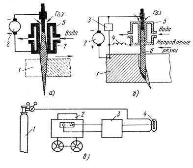
Obtaining a plasma arc. If a stream of any gas is directed into an electric arc, passing it through a small opening of the plasma nozzle (Fig. 96), then the arc column will be compressed, and the resulting plasma is a highly concentrated source of heat with a high temperature reaching 20,000 - 30,000 ° C . The gas that compresses the arc column is called the plasma gas. As plasma-forming gases, either monatomic gases (for example, argon) or diatomic gases (hydrogen, nitrogen) are used. Mixtures of two or more gases and air are also used.
The temperature distribution of a plasma arc with a monatomic gas (argon) at a current of 400 A and a gas flow rate of 0.6 m 3 /h is shown in fig. 97.
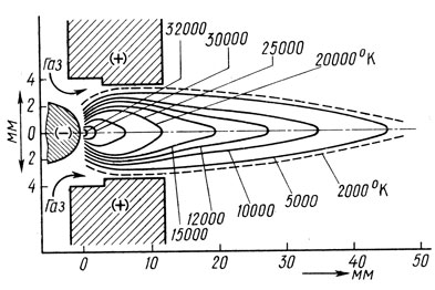
Rice. Fig. 97. Temperature distribution in a plasma jet at an arc current of 400 A and an argon flow rate of 0.6 m 3 /h
A compressed arc can be similar to a welding arc of direct and indirect action. In the first case, one of the electrodes is the metal being processed (Fig. 96, b), in the second - the arc is excited between electrodes independent of it (Fig. 96, a). Accordingly, it is customary to call the compressed arc obtained according to the first scheme - a plasma arc, and according to the second scheme - a plasma jet.
For separation cutting of metals, it is more advisable to use a plasma arc, since it has been found that it has a higher efficiency, and the plasma torch is less subject to wear.
Plasma-arc cutting has found wide application in the processing of those metals and alloys that are not amenable to oxygen cutting: high-alloy steels, aluminum, titanium and their alloys, copper, etc.
Plasma-arc cutting consists in the penetration of metal in a narrow section along the cut line and the removal of molten metal by a plasma jet formed in the arc. The plasma arc is mainly used for separation cutting.
Equipment for plasma-arc cutting. The set of equipment for plasma-arc cutting includes a cutter (plasma torch), a process control panel, an arc power source electric shock, cylinders with plasma-forming gases and a mechanism for moving the plasma torch along the cut line.
The cutter consists of two units: electrode and nozzle. There are plasma torches with axial and vortex supply of plasma gas to compress the arc. Axial supply of plasma gas is used in wide nozzles. With vortex supply, the plasma-forming gas is introduced into the zone of the cathode and the column through channels located tangentially to the walls of the arc chamber of the plasma torch. In this case, a vortex gas flow with a spiral motion is created in the chamber. The vortex supply of the plasma-forming gas ensures the mixing of the gas in the arc column and the uniformity of the gas envelope around the column.
With axial feed, the end of the electrode (a tungsten rod with a diameter of 2 to 6 mm and a length of up to 100 - 150 mm) has the shape of a pointed rod with an angle of 20 - 30 °, and with a vortex feed, there are replaceable sleeve cathodes at the end of the electrode.
Water is used to cool plasma torches, and compressed air is used in low-power plasma torches.
Tungsten (or with an admixture of oxides of lanthanum, yttrium, thorium) electrode is used to work in inert gases; when cutting in oxidizing gases, the electrode in the cathode area must be protected with an inactive gas.
Cutting plasma torches with film cathodes. Zirconium and hafnium have the ability to form a film on the cathode. At high temperatures, an oxide-nitride film with electrical conductivity is easily formed on the cathode surface. Such a cathode can operate for a long time in an oxidizing environment, for example, in compressed air.
The intensity of wear of the cathode inserts and electrodes depends on the strength of the operating current. The higher the current, the faster the insert wears out. For machine plasma torches with zirconium cathode inserts and a flow-through water cooling system, the maximum operating current is 250–300 A. In this case, the duration of the cathode usually does not exceed 4–6 hours.
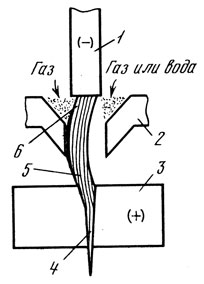
Of great importance in plasma torches is the design of the nozzle. The smaller the diameter of the nozzle and the greater its length, the higher the energy concentration, the arc voltage and the greater the plasma flow rate; the arc becomes rigid, its cutting ability increases. However, the diameter and length of the nozzle are determined by the power of the operating current and the gas flow. If the nozzle diameter is very small or its length is very large, a so-called double arc may occur (Fig. 98), in which the cutting arc splits into two parts: one between the cathode and the inside of the nozzle, and the other between outer surface nozzle and cut product. The double arc can burn simultaneously with the cutting one, but it exists for a short time and then disappears. The double arc operates outside the shielding gas zone and from this the metal of the edges is contaminated and melted; a double arc can damage the forming tip nozzle. Most often, a double arc occurs at the moment of excitation of the cutting arc. The cutting arc is excited by an oscillator or capacitor devices. To prevent a double arc during the ignition of the cutting one, it is necessary to smoothly increase the operating current. This is achieved by magnetic, thyristor and other devices.
For plasma-arc cutting, DC arc power supplies with steeply falling current-voltage characteristics are used. When cutting large thicknesses (more than 80 mm), only special power sources with increased open circuit voltage are used, for example, of the IPG-500 type, etc. (Table 24).
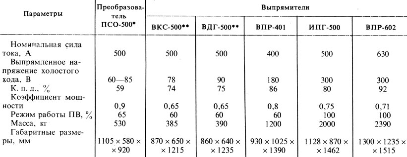
* (It is possible to switch the windings to increase the voltage.)
** (Switching of windings is possible.)
According to GOST 14935 - 691, rectifiers for plasma-arc cutting must have an open circuit voltage of 180 - 500 V and a current of 130 - 1000 A.
For plasma-arc cutting, you can also use standard welding arc power sources (some of them are shown in Table 24). Since the voltage of plasma torches, as a rule, is greater than the open circuit voltage of these sources, two or three sources must be connected in series.
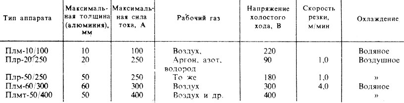
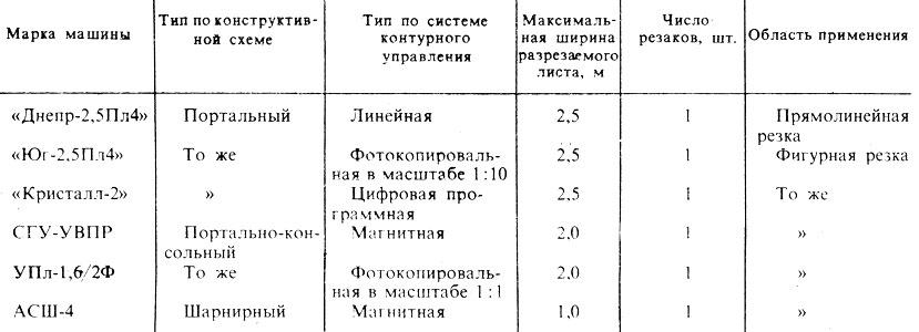
Plasma arc cutting machines do not differ from oxyfuel cutting machines in terms of the principle of operation and the design of the mechanical device. Equipment for plasma-arc cutting must comply with GOST 12221 - 71: Plr - for manual cutting; Plrm - for manual and machine cutting; Plm - for machine cutting; Plmt - for machine precise cutting.
Manual cutting of steel up to 20 mm thick with a working current of up to 250 A is carried out using the PLR-20/250 apparatus.
The device Plr-50/250 is designed for cutting steel up to 50 mm thick at a working current up to 250 A. The medium is compressed air, nitrogen, argon, hydrogen, gas mixtures. The device has air cooling, it is convenient to use it in the workshop and during installation.
Cutting steel with a thickness of 60 - 80 mm can be performed by a Plrm type device with a power of up to 50 kW; current strength - 400 A, power supply voltage - 180 V. Increased voltage and current provide the best quality cut and higher cutting speed. When protecting a tungsten cathode, oxygen can be used as a working medium.
The main technical data of some devices and machines are given in Table. 25 and 26.
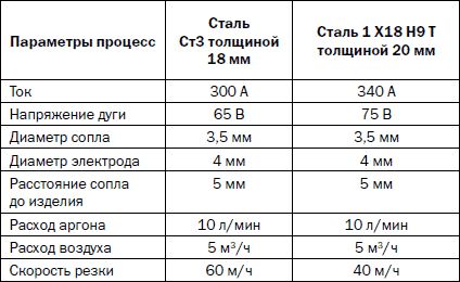
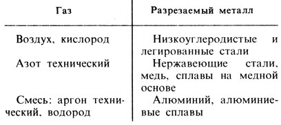
Technology of plasma-arc cutting. The parameters of the plasma arc cutting mode are: nozzle diameter, current strength, plasma arc voltage, cutting speed and gas consumption. The plasma-forming gas is chosen according to the nature of the metal being cut (Table 27).
Choice of cutting mode. Approximate modes of plasma-arc cutting of metals with compressed air for the Plm-60/300 apparatus are given in Table. 28.
Note. The diameter of the tungsten cathode is equal to the diameter of the forming nozzle
The maximum allowable thicknesses of the metal cut by the plasma arc are given in Table. 29.
![]()
Plasma-arc cutting is advisable to use mainly on machines, since high cutting speeds make it very difficult to control the process. For example, steel with a thickness of 1.5 mm is cut with a 50 kW machine at a speed of 20 m / min, and steel with a thickness of 10 mm - at a speed of 3 - 4 m / min. As the electric power of the plasma increases, the cutting speed increases even more. Modern plasmatrons have electrical power 150 kW and more; the thickness of the cut sheets reaches 100 mm.
Plasma-arc cutting of steel up to 50 mm thick is economically feasible. Technical difficulties limit the thickness of cut blanks with simultaneous removal of edges for welding to 30 mm.


How to understand: will the kitten be fluffy?
What kind of light alcohol can be drunk for pregnant women: the consequences of drinking
Why do the legs swell in the ankles and ankles of the feet in pregnant women: causes and methods of treatment
The wedding of Prince Harry and Meghan Markle: scandalous and secret details of the marriage (photo) The future marriage of Prince Harry year NTV
How to close white plums for the winter