As I remember now, on February 23rd I came across a post on Tudey, where a person wanted to engrave printed circuit boards on a 3D printer. In the comments, they advised not to torture the printer and pay attention to the Cyclone PCB Factory project.
Fired up with the idea. Later, at some point, I even regret that I took it, but it will be much later.
I dreamed of my own CNC router for printed circuit boards for a very long time, it was the second Wishlist after a 3D printer. I decided to repeat the project, especially since I already had something in the bins.
The original project is on github.
I downloaded the project files and without hesitation began to print the details. Managed in about a week. Printed everything except the Z axis.
There are no detailed photographs of all the details. Someone took a screenshot of the print settings and the result. Nozzle 0.4, layer height 0.24. I also printed with a layer of 0.28 - it prints quite normally.
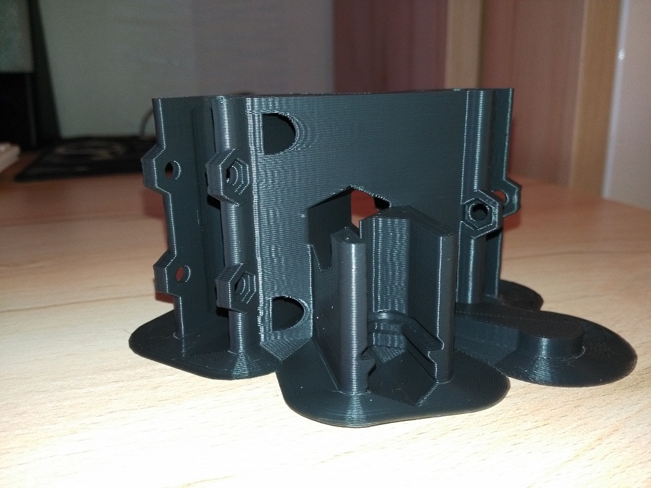
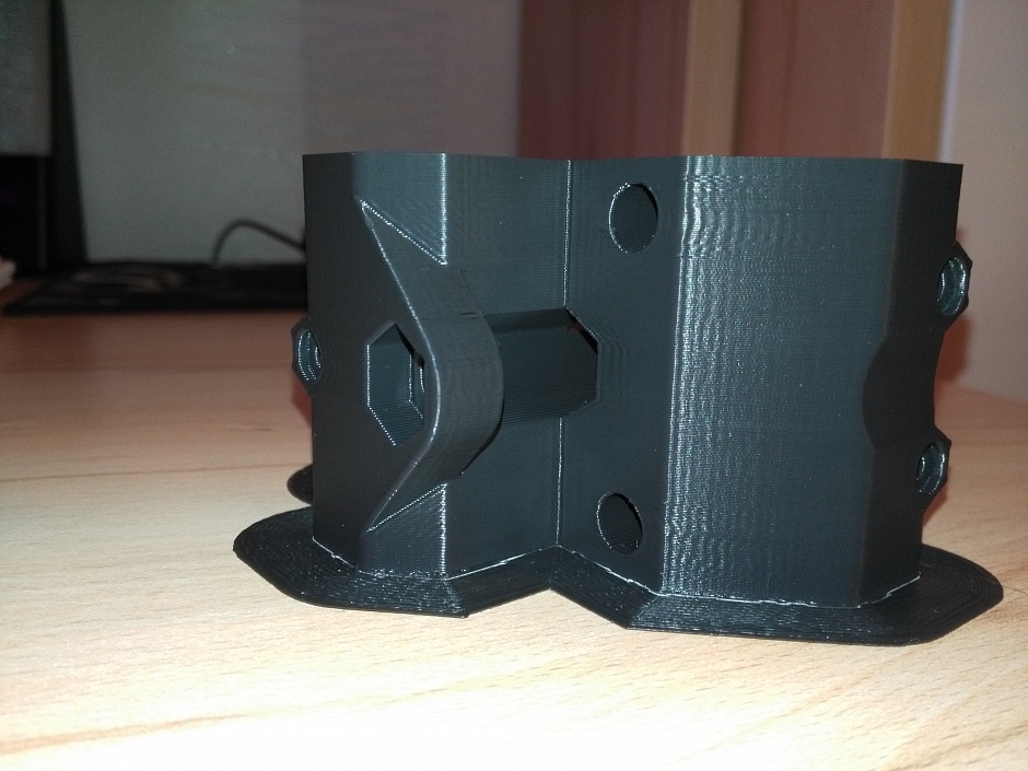
I wanted to make the machine colored, so miscellaneous details printed with plastic different color. Plastic used ABS Prostoplast. Cosmos colors, grassy green, scarlet sunset.
It would be better to print everything in gray space. Red and green turned out to be quite fragile and some of the parts cracked during assembly. Something was cured with acetone, something was reprinted.
Accessories:
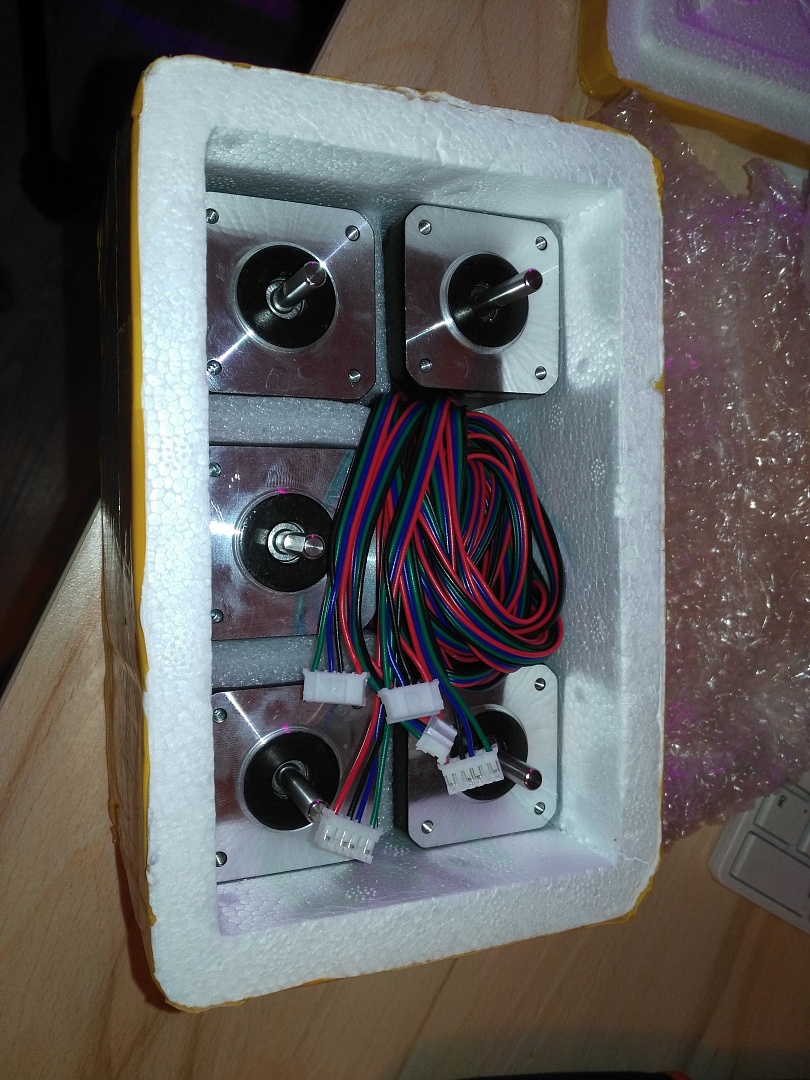
I had three free stepper motors, I bought them for a 3D printer project, I decided to temporarily use them.

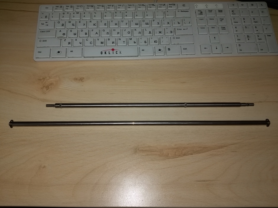
I got 8mm guides from inkjet printers, tearing several printers into organs. Wool local commissions, Avito. Donors were HP inkjet printers for 100-200 rubles apiece. The long guide was sawn into two parts, on the X and Z axes.
The paper clamp from which I removed the rubber rollers went to the Y axis. The length was just enough to cut along the knurling.

Linear bearings remained from the 3D printer, I transferred the printer to bronze bushings with polka dots.
As electronics, I decided to use one of my Arduino Uno on atmega328p. I bought a cnc shield 3.0 board for Arduino on Ali for 200 kopecks.
Power supply 12V from Leroy Merlin. I bought to power three 12V halogens, but he did not pull them. I had to repair the transformer for Tachibra halogens, and this power supply took root on the machine.
I installed the 8825 drivers on the 3D printer, I still have a4988 from the printer. And put them on the machine.
I ordered 608ZZ bearings on Ali, a dozen for 200 rubles with kopecks ..
I planned to use my Chinese GoldTool engraver as a spindle.
M8 threaded studs got from work for free, left from some kind of installation. Picked up almost "from the trash."
While the project was being printed and the details were moving with Ali, I asked a furniture maker friend to cut out a base and a table from MDF. He was not too lazy and did not regret the scraps, sawed out 2 bases and 2 tables. Pictured is one of the sets.
I didn’t have plywood in the bins, a greedy animal did not allow me to buy a sheet of plywood. By the way, MDF came up very well.
Began to assemble the machine. Everything would be fine, but the standard 13 nuts fell through and dangled inside the gear, the 14 nuts did not fit into the gears. I had to melt the 14th nuts into the gears with a soldering iron.
Gears or dangling on axles stepper motor, or did not climb.
The nuts of the m3 screws were scrolled in the landing slots.
I found several square nuts for m3 thread (I once dismantled some kind of plug from it), which fit perfectly and did not scroll. At work, I also found such plugs and put them on nuts. Basically, these are guide mounts. regular nuts for the m3 thread, it was necessary to hold the screwdriver with a thin sting so that it would not scroll.
Somehow collected. Later, while reading topics about Cyclone, I came across recycled machine parts for metric fasteners.
From this set, I re-printed the gears and the mount of the limit switch along the Z axis. It’s a pity I didn’t come across this set of spare parts earlier. I would print these parts.
Hoping to use my Chinese engraver, I first printed out one dremel mount from the kit, then the second. It did not fit, my engraver did not climb into one. The original dremel, the simplest, cost a little over three thousand rubles. For what???
Extra parts.

And yet, linear bearings in their nests dangled like something in an ice hole.
I had to order a 200W spindle with an ER11 collet clamp for a little over a thousand. Successfully got on discounts and used the coupon.
While the spindle was driving, I printed out a mount for it from the machine kit. And again a puncture, it is just as flawed. And not a word about the clamp for the spindle.

As a result, I found and printed out this mount for a 52mm spindle
After a little refinement, the mount fit on the machine, the spindle entered it well.
But the bearings on the Cargo bushings had to be removed from them. Delivered Chinese LM8UU
Separately, I want to say about the Chinese bearings 608zz. New bearings with backlash. Terrible. One that is relatively inexpensive. We did not look for bearings.
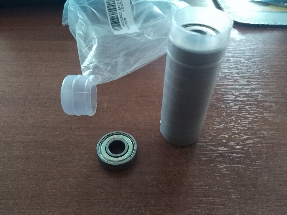
By the way, the bearings entered the seats in the same way as something in an ice hole. In the seats, the bearings dangled. I don't know if this is a bug or a feature. As a result, he wound electrical tape on the bearing races.
Chinese lm8uu and lm8luu from a 3D printer also turned out to be rubbish. As a result, I made plain bearings on Cargo 141091 bushings for the Y axis. I printed out a plastic clip and inserted a pair of bushings into it. The resulting bearings are inserted into the mounts.
On the Z axis I chose the more or less lively lm8uu. I put the lm8uu upper bearing on the X axis, and instead of the two lower ones, I printed out a plastic clip according to the lm8luu size and inserted a pair of Cargo bushings into it.
Luckily I bought them at the time. Useful.
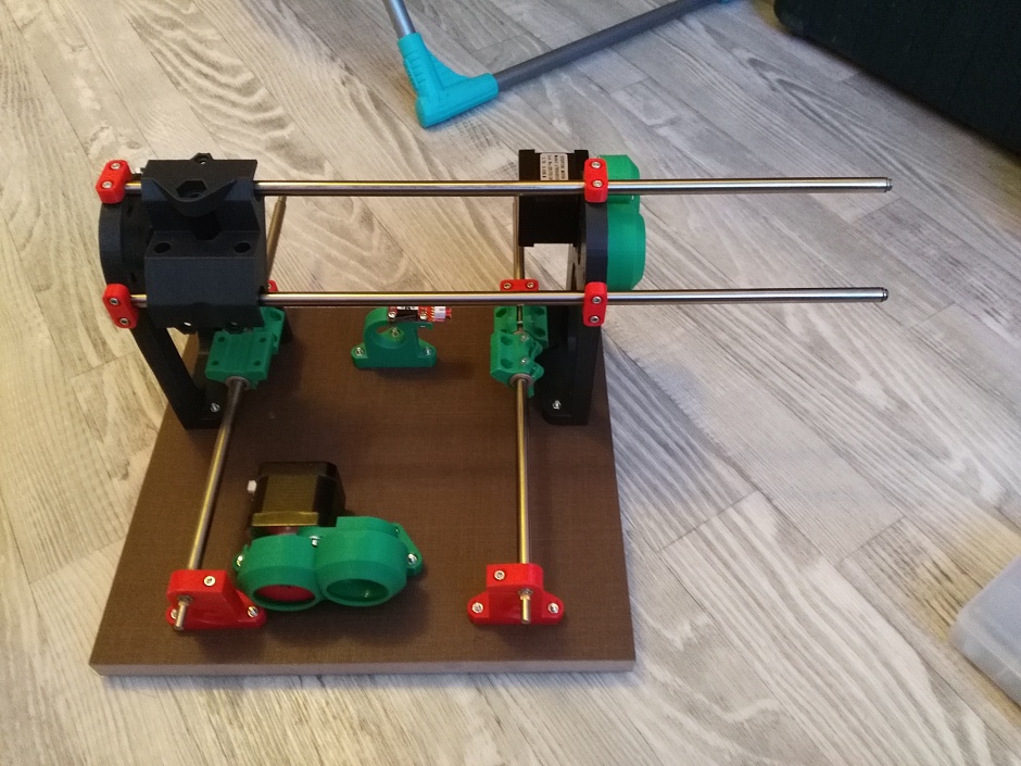
During the assembly of the machine, I regretted that I had taken it. But, there was nowhere to go, it was necessary to complete the project. Collected. Launched!
Some more photos of the build process.
The very beginning of the build...
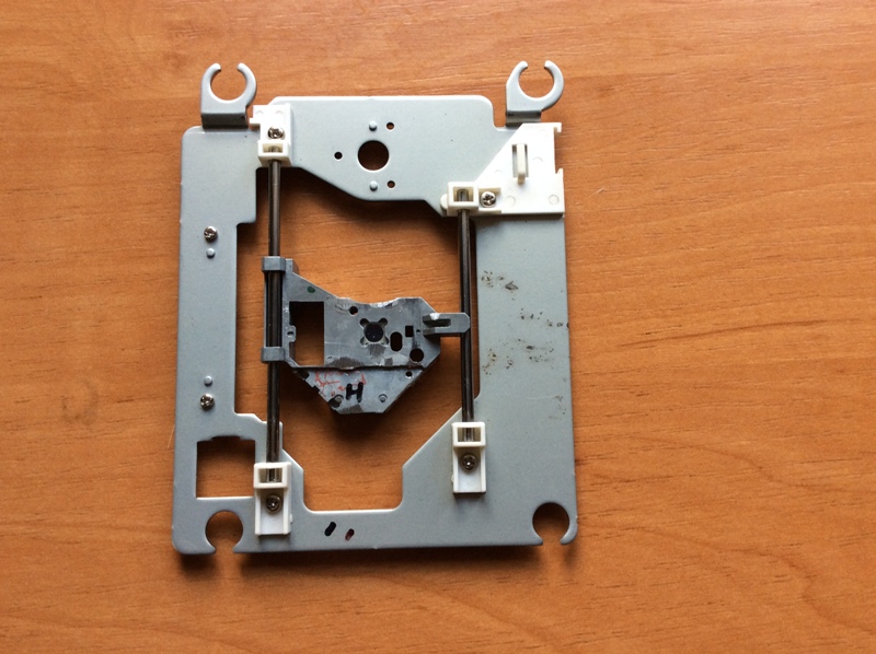
Tired, in general, of drilling boards with a manual drill, so it was decided to make a small drilling machine exclusively for printed circuit boards. There are plenty of designs on the Internet, for every taste. After looking at several descriptions of such drills, I came to the decision to repeat the drilling machine based on elements from an unnecessary, old CD ROM. Of course, for the manufacture of this drilling machine, you will have to use the materials that are at hand.
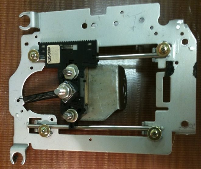
From the old CD ROM, for the manufacture of a drilling machine, we take only a steel frame with two guides mounted on it and a carriage that moves along the guides. In the photo below, all this is clearly visible.
 The drill motor will be mounted on the movable carriage. To mount the electric motor to the carriage, an L-shaped bracket was made from a strip of steel 2 mm thick.
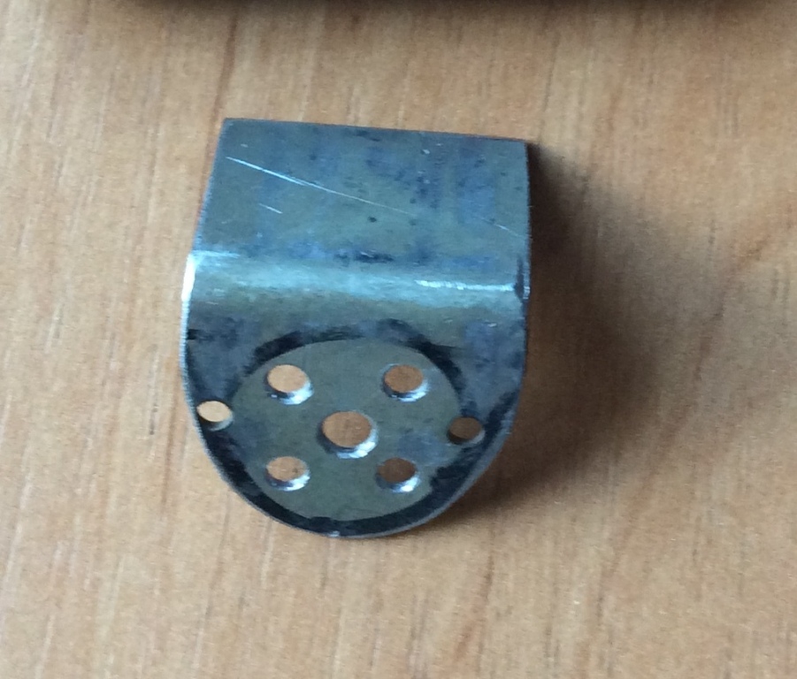
We drill holes in the bracket for the motor shaft and the screws for its fastening.
In the first variant, an electric motor of the DP25-1.6-3-27 type with a supply voltage of 27 V and a power of 1.6 W was chosen for the drilling machine. Here he is in the photo:
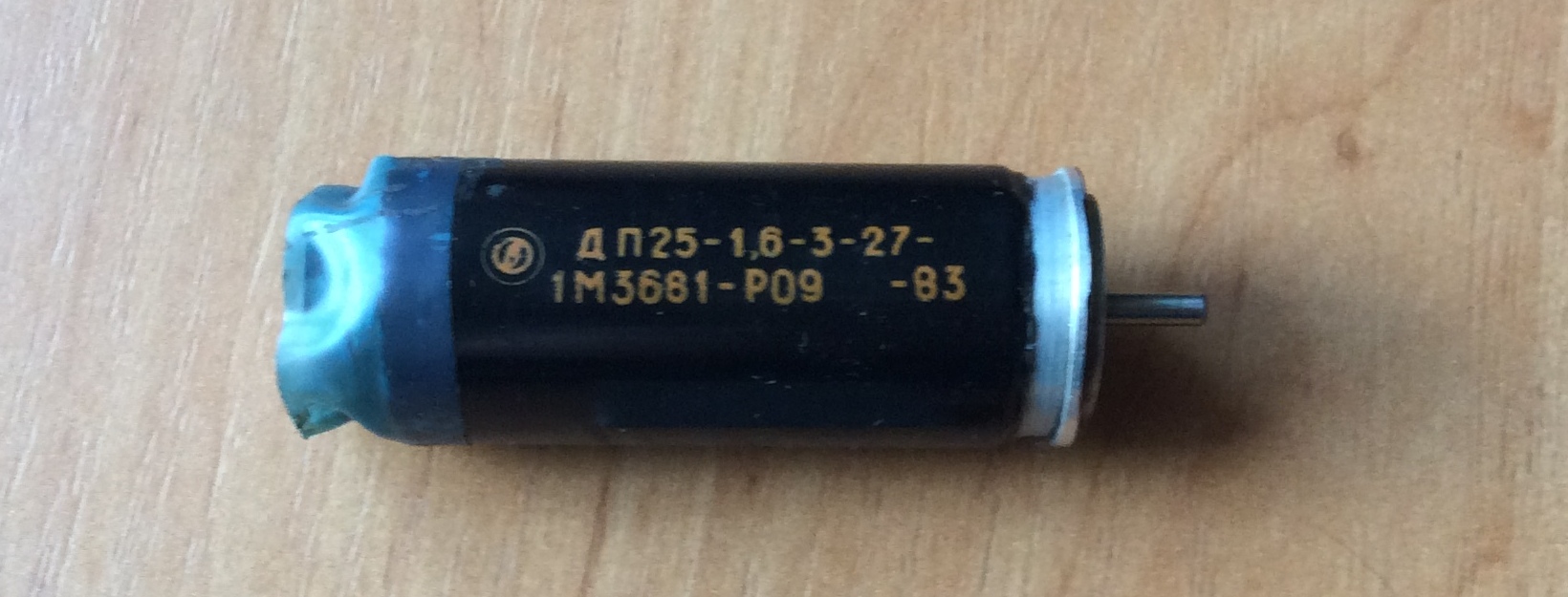
As practice has shown, this engine is rather weak for drilling work. Its power (1.6 W) is not enough - at the slightest load, the engine simply stops.
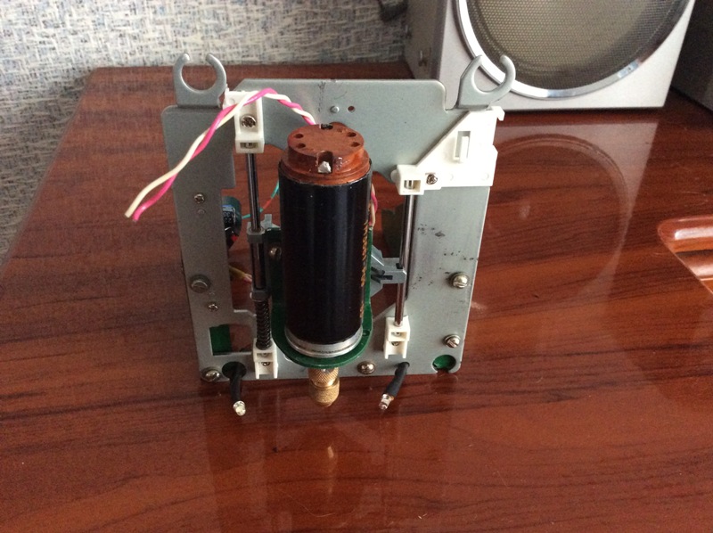
This is what the first version of the drill with the DP25-1.6-3-27 engine looked like at the manufacturing stage:
Therefore, I had to look for another electric motor, more powerful. And the manufacture of the drill has stalled ...
Continuation of the manufacturing process of the drilling machine.
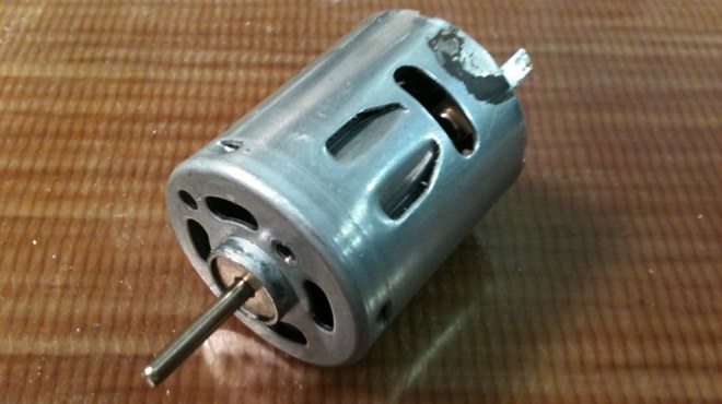
After some time, an electric motor from a disassembled faulty Canon inkjet printer fell into the hands:
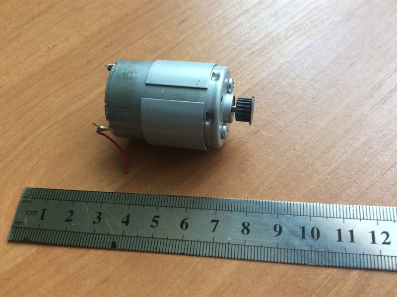
There is no marking on the engine, so its power is unknown. A steel gear is mounted on the motor shaft. The shaft of this motor has a diameter of 2.3 mm. After removing the gear, a collet chuck was put on the motor shaft and several test drillings were made with a drill with a diameter of 1 mm. The result was encouraging - the "printer" engine was clearly more powerful than the engine DP25-1.6-3-27 and freely drilled textolite 3 mm thick at a supply voltage of 12 V.
Therefore, the manufacture of the drilling machine was continued ...
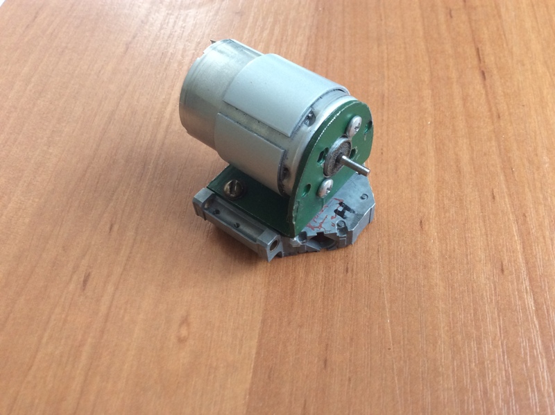
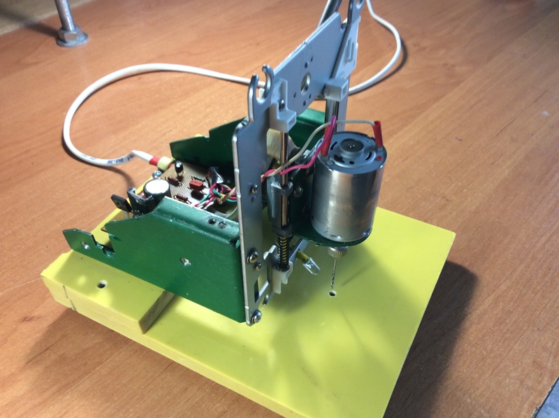
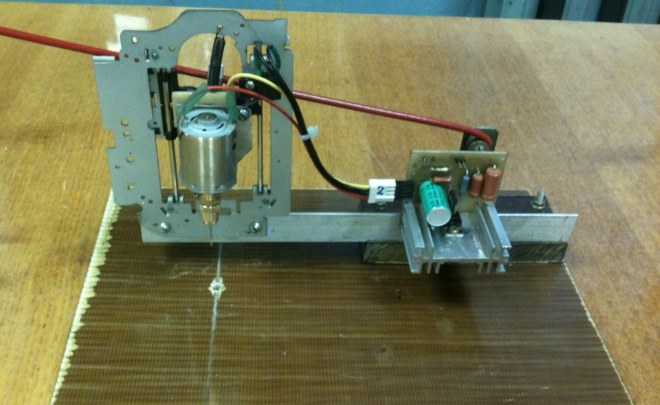
We fix the electric motor with the L-shaped bracket to the movable carriage:

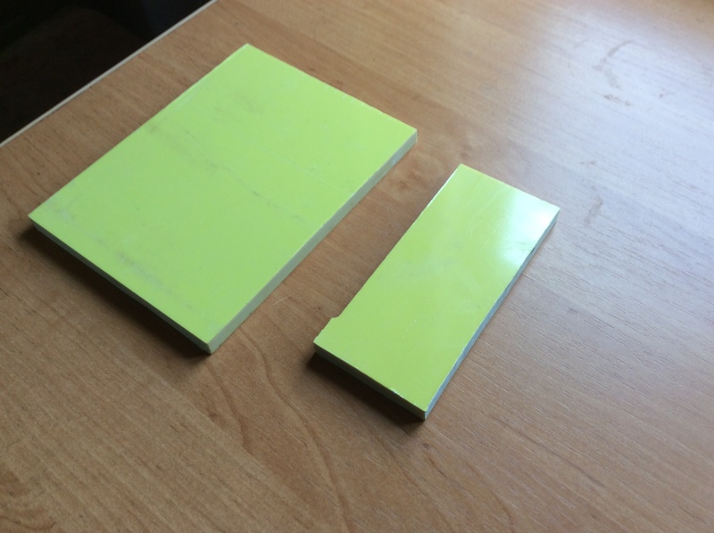
The base of the drilling machine is made of fiberglass 10mm thick.
In the photo - blanks for the base of the machine:
To prevent the drilling machine from fidgeting on the table during drilling, rubber feet are installed on the underside:
![]()
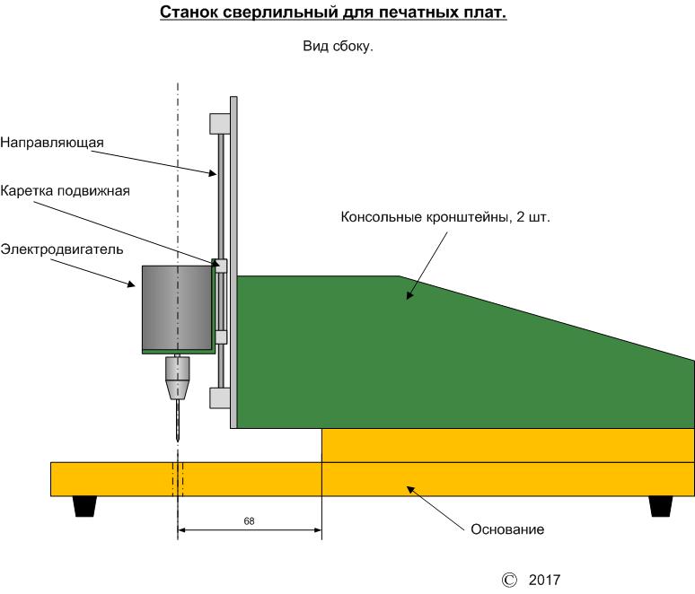
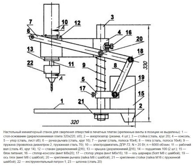
The design of the drilling machine is of a cantilever type, that is, the supporting frame with the engine is fixed on two cantilever brackets, at some distance from the base. This is done in order to ensure that sufficiently large printed circuit boards are drilled. The design is clear from the sketch:


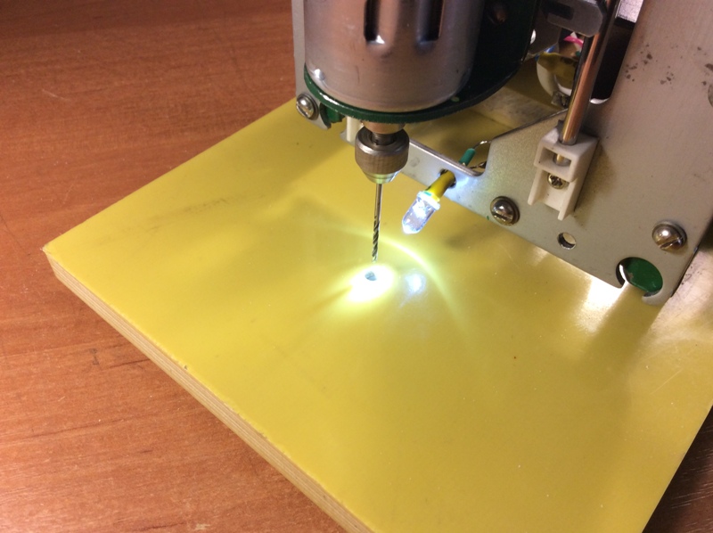
The working area of the machine, the white LED backlight is visible:
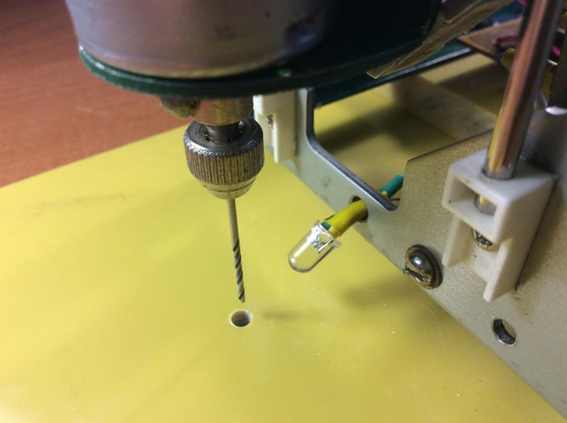
This is how the illumination of the working area is implemented. The photo shows excessive brightness of the lighting. In fact, this is a false impression (this is a camera glare) - in reality everything looks very good:
Cantilever design allows drilling boards with a width of at least 130 mm and an unlimited (within reasonable limits) length.
Measurement of the dimensions of the working area:
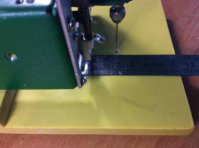
The photo shows that the distance from the stop to the base of the drilling machine to the axis of the drill is 68mm, which ensures the width of the processed printed circuit boards is at least 130mm.
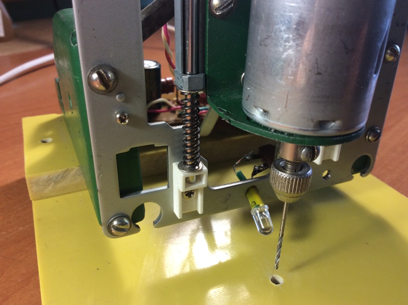
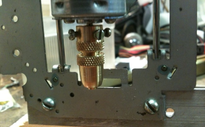
To feed the drill down when drilling, there is a pressure lever - visible in the photo:
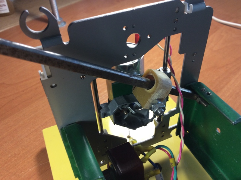
To hold the drill over printed circuit board before the drilling process, and returning it to its original position after drilling, a return spring is used, which is worn on one of the guides:
The system of automatic adjustment of engine speed depending on the load.
For ease of use of the drilling machine, two variants of engine speed controllers were assembled and tested. In the original version of the drill with the DP25-1.6-3-27 electric motor, the regulator was assembled according to the scheme from the Radio magazine No. 7 for 2010:
This regulator did not want to work as expected, so it was mercilessly thrown into the trash.
For the second version of the drilling machine, based on an electric motor from a Canon inkjet printer, on ham radio cat website another circuit of the motor shaft speed controller was found: 
This regulator provides the operation of the electric motor in two modes:
- When there is no load, or, in other words, when the drill does not touch the printed circuit board, the motor shaft rotates at a reduced speed (100-200 rpm).
- With an increase in the load on the engine, the regulator increases the speed to the maximum, thereby ensuring the normal drilling process.
The motor speed controller assembled according to this scheme worked immediately without tuning. In my case, the idle speed was about 200 rpm. At the moment the drill touches the printed circuit board, the revolutions increase to the maximum. After drilling is completed, this regulator reduces the engine speed to the minimum.
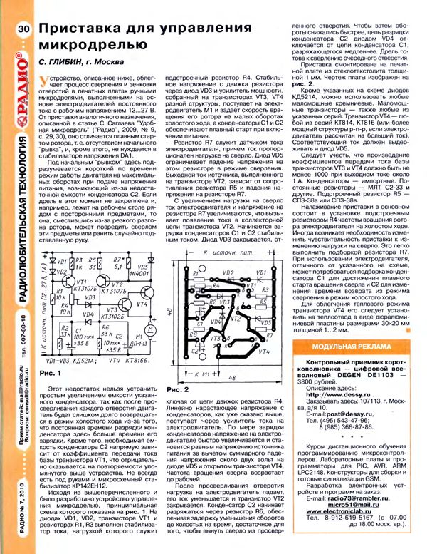
The motor speed controller was assembled on a small printed circuit board:
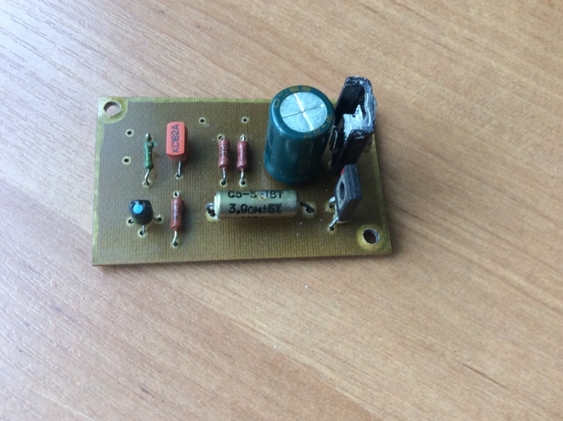
The KT815V transistor is equipped with a small radiator.
The regulator board is installed at the rear of the drilling machine:
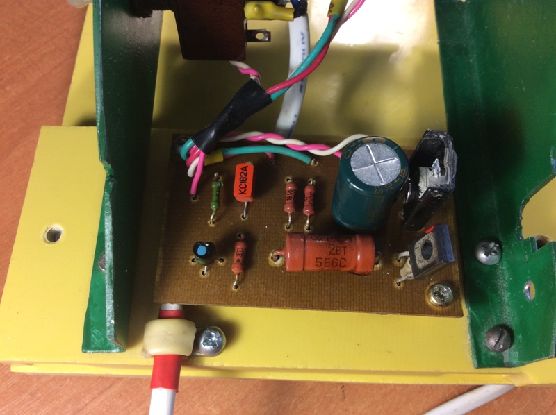
Here, the resistor R3 with a nominal value of 3.9 ohms was replaced by an MLT-2 with a nominal value of 5.6 ohms.
The testing of the drilling machine was successful. The system of automatic adjustment of the frequency of rotation of the motor shaft works clearly and without fail.
A short video about the operation of the drilling machine:
Update from 08/01/2017:
On the control board, in addition to the engine speed controller itself, there is also a simple voltage regulator for the supply voltage of the LED for backlighting the working area. Complete control board diagram: 
Drilling machine for printed circuit boards belongs to the category of mini-equipment for special purposes. If desired, such a machine can be made with your own hands, using available components for this. Any specialist will confirm that it is difficult to do without the use of such an apparatus in the production of electrical products, the circuit elements of which are mounted on special printed circuit boards.
General information about drilling machines
Any drilling machine is necessary in order to be able to efficiently and accurately machine parts made from various materials. Where high precision machining is required (and this also applies to the process of drilling holes), from technological process should be excluded as much as possible. manual labor. Similar tasks can be solved by anyone, including home-made ones. It is practically impossible to do without machine equipment when processing hard materials, for drilling holes in which the efforts of the operator himself may not be enough.
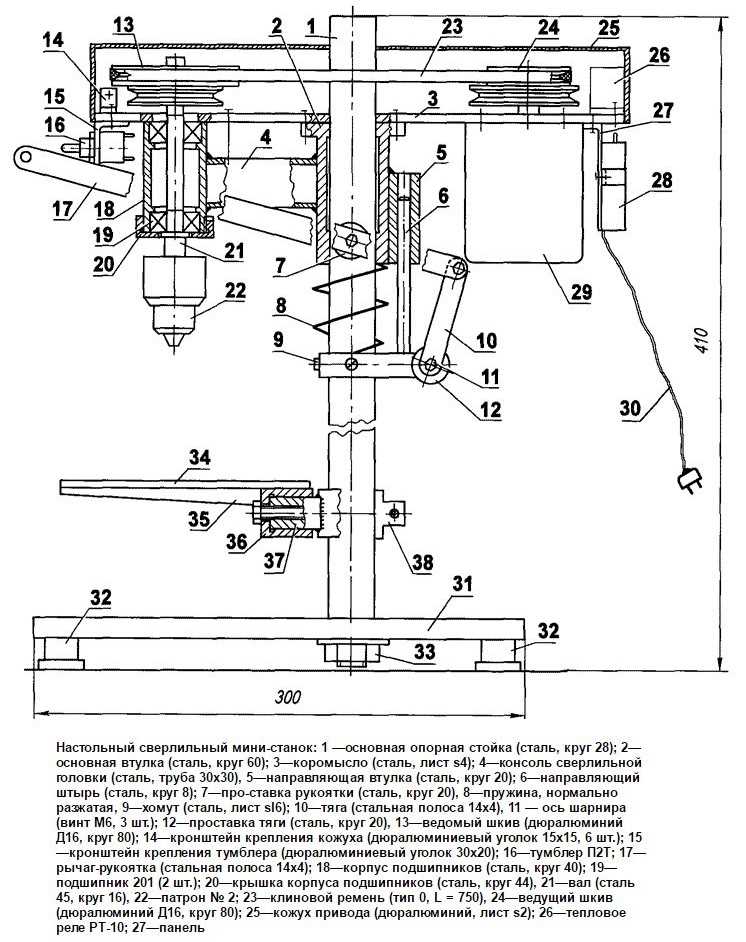
The design of a bench drill with a belt drive (click to enlarge)
Any drilling machine is a structure assembled from many constituent parts, which are securely and accurately fixed relative to each other on the carrier element. Some of these nodes are rigidly fixed to the supporting structure, and some can move and be fixed in one or more spatial positions.
The basic functions of any drilling machine, due to which the processing process is ensured, is the rotation and movement in the vertical direction of the cutting tool - the drill. On many modern models such machines, the working head with the cutting tool can also move in a horizontal plane, which allows using this equipment for drilling several holes without moving the part. In addition, automation systems are being actively introduced into modern drilling machines, which significantly increases their productivity and improves processing accuracy.
Below, for example, several design options for boards are presented. Any of these schemes can serve as a model for your machine.
Features of equipment for drilling holes in printed circuit boards
The machine for drilling printed circuit boards is one of the varieties drilling equipment, which, given the very small size parts processed on it, belongs to the category of mini-devices.
Any radio amateur knows that the printed circuit board is the base on which the constituent elements of the electronic or electrical circuit. Such boards are made from sheet dielectric materials, and their dimensions directly depend on how many circuit elements need to be placed on them. Any printed circuit board, regardless of its size, simultaneously solves two problems: accurate and reliable positioning of circuit elements relative to each other and ensuring the passage of electrical signals between such elements.
Depending on the purpose and characteristics of the device for which the printed circuit board is created, it can accommodate both a small and a huge number of circuit elements. To fix each of them in the board, it is necessary to drill holes. Very high requirements are imposed on the accuracy of the location of such holes relative to each other, since it depends on this factor whether the elements of the circuit will be located correctly and whether it will be able to work at all after assembly.

The complexity of processing printed circuit boards also lies in the fact that the main part of modern electronic components is miniature in size, therefore, the holes for their placement must also have a small diameter. To form such holes, a miniature tool (in some cases even micro) is used. It is clear that it is not possible to work with such a tool using a conventional drill.
All of the above factors led to the creation of special machines for forming holes in printed circuit boards. These devices have a simple design, but they can significantly increase the productivity of such a process, as well as achieve high processing accuracy. Using a mini-drilling machine, which is easy to make with your own hands, you can quickly and accurately drill holes in printed circuit boards designed to complete various electronic and electrical products.
How does a machine for drilling holes in printed circuit boards
The machine for forming holes in printed circuit boards differs from classical drilling equipment in its miniature size and some features of its design. The dimensions of such machines (including home-made ones, if the components are correctly selected for their manufacture and their design is optimized) rarely exceed 30 cm. Naturally, their weight is insignificant - up to 5 kg.
If you are going to make a mini-drilling machine with your own hands, you need to pick up components such as:
- bearing frame;
- stabilizing frame;
- a bar that will ensure the movement of the working head;
- shock-absorbing device;
- handle to control the movement of the working head;
- device for fastening the electric motor;
- the electric motor itself;
- power unit;
- collet and adapters.
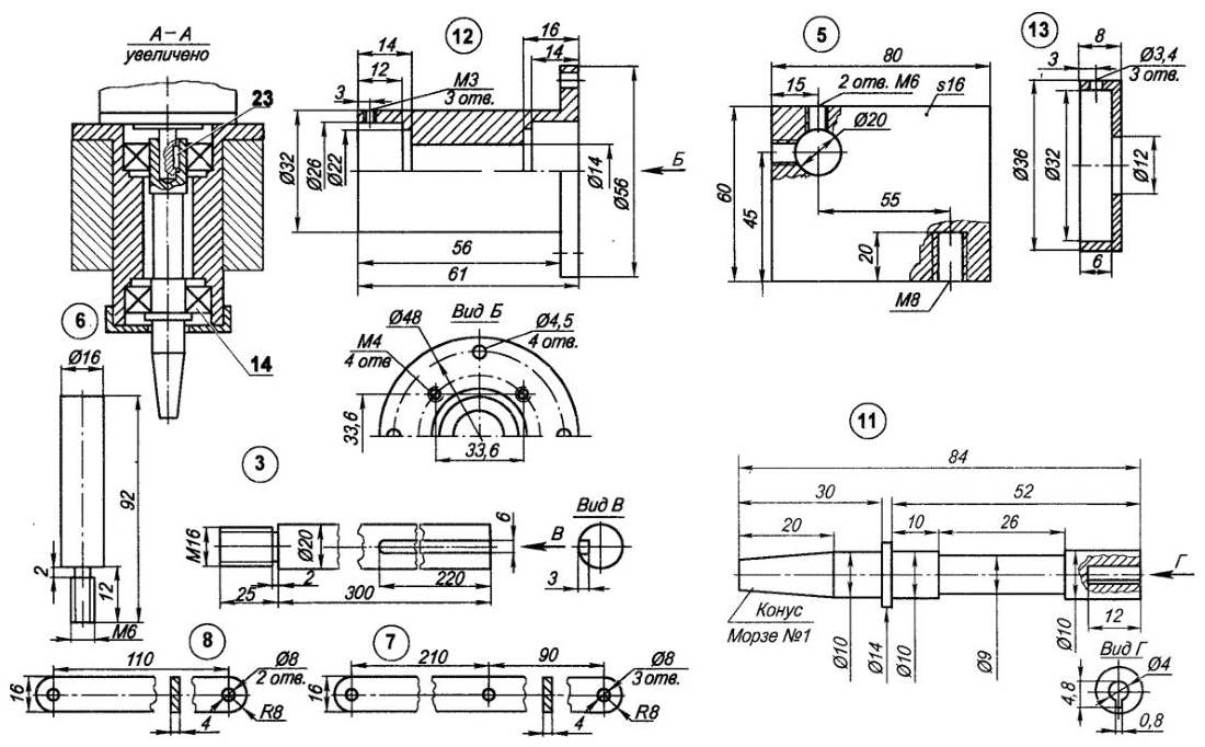
Drawings of machine parts (click to enlarge)
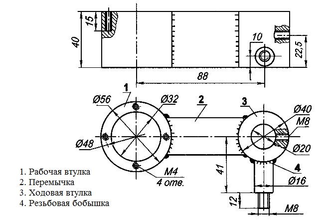
Let's figure out what all these nodes are for and how to assemble a home-made mini-machine from them.
Structural elements of a drilling mini-machine
Self-assembled mini-drilling machines can be seriously different from each other: it all depends on what components and materials were used to make them. However, both factory and home-made models of such equipment work on the same principle and are designed to perform similar functions.
The supporting element of the structure is the base frame, which also ensures the stability of the equipment during the drilling process. Based on the purpose of this structural element, it is desirable to make a frame from a metal frame, the weight of which should significantly exceed the total mass of all other equipment components. If you neglect this requirement, you will not be able to ensure the stability of your homemade machine, which means that you will not achieve the required drilling accuracy.
The role of the element on which the drilling head is attached is performed by a transitional stabilizing frame. It is best made from a metal rail or corners.
The bar and shock-absorbing device are designed to ensure vertical movement of the drilling head and its springing. As such a bar (it is better to fix it with a shock absorber), you can use any design (it is only important that it performs the functions assigned to it). In this case, a powerful hydraulic shock absorber may come in handy. If you don’t have such a shock absorber, you can make the bar yourself or use spring structures taken from old office furniture.
The vertical movement of the drilling head is controlled using a special handle, one end of which is connected to the body of the mini-drilling machine, its shock absorber or stabilizing frame.

The engine mount is mounted on a stabilizing frame. The design of such a device, which can be a wooden block, clamp, etc., will depend on the configuration and design features other components of the drilling machine for printed circuit boards. The use of such a mount is due not only to the need for its reliable fixation, but also to the fact that you must bring the motor shaft to the required distance from the travel bar.
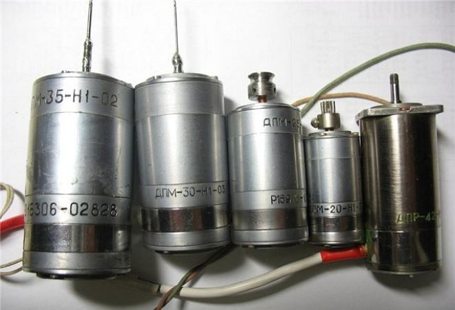
The choice of an electric motor that can be equipped with a do-it-yourself mini-drilling machine should not cause any problems. As such a drive unit, you can use electric motors from a compact drill, cassette recorder, computer drive, printer, and other devices that you no longer use.
Depending on which electric motor you found, are selected clamping mechanisms for fixing drills. The most convenient and versatile of these mechanisms are cartridges from a compact drill. If a suitable cartridge could not be found, a collet mechanism can also be used. Be sure to size the clamping device so that very small drills (or even micro-sized drills) can be clamped in it. To connect the clamping device to the motor shaft, it is necessary to use adapters, the dimensions and design of which will be determined by the type of the selected motor.
Depending on which electric motor you installed on your mini drilling machine, you need to choose a power supply. With this choice, attention should be paid to ensure that the characteristics of the power supply fully correspond to the voltage and current parameters for which the electric motor is designed.
15
Make your own PCB drilling machine from a TEAC CD drive and join the protection society for typewriters, microscopes, enlargers and astrolabes
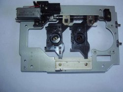
After reading articles about the achievements of members of the forum in the field of machine tool building (well done, guys!) With the mention of SD drive units, I reached into the trap box and took out a dead SD TEAC.
Looking at the carriage holding the laser module, I immediately realized that this is an almost finished drill head drive unit! The accuracy of delivery is beyond doubt SAM LASER positioned! But for greater reliability (after all, the drilling head is heavier than the laser), another similar carriage was needed. Fortunately, the same (or almost) was lying nearby. TEAC. Mechanically, they seem to be standard. In short, we remove the carriage from it, install it next to the existing one, and this is what happened:
The working stroke of this tandem is about 10 mm - quite enough. You can, of course, file something in order to increase the drill stroke by bringing the carriages closer together, but it makes no sense - the machine is designed only for drilling boards (at least for me).
PS. One laser could not be dismantled - so you can safely write in the name of the machine - "laser"!
Now you need to think about the bed. We look at the chassis of the same drive:
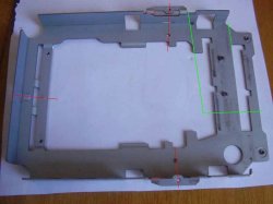
We cut along the red lines, cut the corners to taste. The cut along the green lines will come in handy later. Do not forget to remove burrs - sources of injury. As a result, we get two identical, but symmetrical brackets:
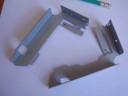
(I didn’t check the corners - after all TEAC- decent company). Having drilled the necessary holes, we assemble the frame, focusing on the shelves and corners on the parts:
Rear view (from inside the machine):
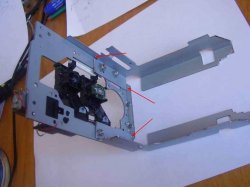
The arrows indicate the places of conjugation of parts. These shelves and corners make assembly very easy! Do not forget to install spring washers under the nuts - after all, the machine! Vibration…
Now you need to think about the drill head. At first I wanted to adapt my DPR-12-2 27V 5000 rpm(for him, he fenced the second carriage, and, as it turned out, not in vain at all!). But my motor on this design looked like an elephant in a china shop!
STUDY 1. There were two DC motors in the drive.
First, I removed the carriage drive motor (visible in Fig. 1). A plastic sleeve is pressed onto its shaft, which includes a gear and a perforated disk. Having connected 12V to the contacts, I tried to stop the shaft with my fingers - I almost tore off my skin, but the motor did not stop. The diameter of the bushing in a place free from the gear is a little more than 3 mm. Can be fitted to a collet chuck! Carefully sawing off the gear and adjusting the diameter of the sleeve (right on the running engine), I try to press the cartridge onto the sleeve:

To be honest, I didn’t succeed - I got beats and vibration. I tried to put locking screws (without heads) instead of screws - almost the same result. Most likely, this is due to the ratio of the masses of the motor and the cartridge. Maybe someone will succeed - the motor deserves close attention.
Then my attention was drawn to the ejector drive motor. I had a collet chuck from a Soviet drill - you probably remember - a small motor with a thin shaft and a hefty power adapter. So, the cartridge from this drill seat almost matched the diameter of the shaft. I wound one layer of copper foil around the shaft - and the cartridge had to be pressed in a vice (with caution). In general, I think a good turner should cope with this task, but I was just lucky.
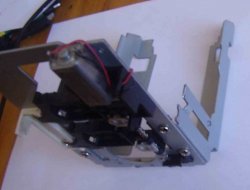
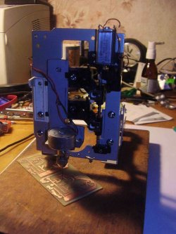
We continue. From the remnants of the SD chassis (see Fig. 2, green lines), we make a suitable bracket and install a drilling head on it. We attach the unit with screws to the carriages in place:

So, the bed is ready!
You need a base for the machine. Without a foundation, this is some kind of drill, or something ...
PS. When I was disassembling the SD, the thought flashed through to use its case as a base - it would have turned out to be almost complete unification!
But! Firstly, the toad crushed, and secondly (also important) - if you mount the bed directly on the body, you need to drill a hole in the body for the drill to exit. And once the hole (albeit a small one!) - then in a week the body will be clogged with chips. In order not to drill, it would be necessary to install a false table on the case, in which this same hole would be drilled. Then why do we need a corps? In short, the toad won. I'll tell you a secret - I stole a cutting board in the kitchen (there is even a hole in it - to hang the machine on a carnation). Best of all, probably, a plate made of textolite-getinaks with a thickness of about 8-12 mm is suitable. Here, who has what. Although remounting the machine on a new base - ugh! - Tighten 4 screws.
So, we mount the frame on the kitchen base:
Because we will drill not only small boards, we provide a gap between the frame and the base. We provide it by installing the frame on the screws:
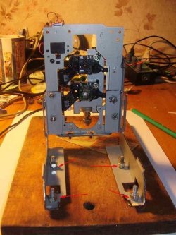
I didn’t come up with anything smarter to ensure a gap, how to screw one M4 nut onto the mounting screws. You can washers - in short, the size of the gap can be adjusted - the main thing is that the board moves freely in this gap. Working field(distance from the center of the drill to the nearest support) - 80 mm - enough for my purposes (after all, if it doesn’t fit, you can also drill the center of the board manually). Yes, and this is not a dogma - you can organize the mounting of the machine in a different way. And you can generally dismantle the machine from the bed and crawl it along the board ...
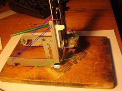
The red arrows indicate the attachment points of the frame. I also thought about mounting the jibs - they are schematically drawn in blue - but it turned out that it was not necessary. Green - the size of the working field.
It is already possible to drill by dismantling the top motor and moving the carriages with your fingers.
Head carriages move smoothly.
But this same engine does not give rest. Well, it's a power supply with a gearbox! Just put the limit switches and press yourself on the pedal button.
STUDY 2. Having connected 12V to the drilling head, I try to apply voltage to the carriage drive motor using the “poke” method. The rush doesn't work. If 12V is applied to the carriage drive motor, the board does not have time to drill through and the mechanical protections on the carriages begin to click. If the voltage is lower, it is drilled, but not always. The carriage drive motor must have low speed and at the same time sufficient power. I think by applying PWM to the carriage drive motor, you can try to achieve success. While we postpone. Maybe someone will have some ideas..
We cut it in red, we get a bracket. I don't really describe it, it's clear from the photo:

We install LEDs “on the fly” on our own outputs to adjust the backlight zone.
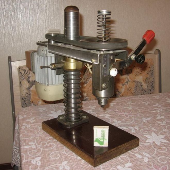
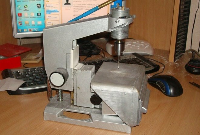
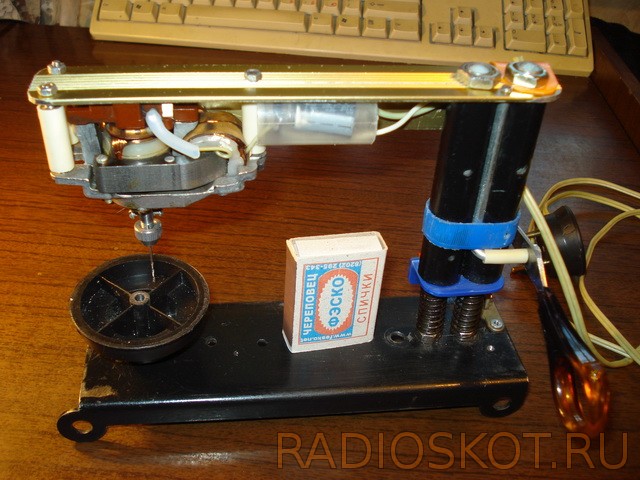
The first version of a desktop machine for drilling circuit boards was made three years ago. He did it purposefully, specifically for drilling boards (it is not intended for another) and exclusively from improvised materials, he did it on " hastily»as a temporary fixture, spent a day off making it. And he took it and "got accustomed" - it turned out to be unusually convenient in work.
The diameter of drills that can be used is from 0.5 to 1 mm inclusive. Sprint start, finish without inertia. He summed up the board, pressed it - the hole was ready, released it - the drill returned to its original position by itself. For all 2-3 seconds. Six months later, once the thing came "to the court", I spent another evening and gave it a more appropriate and acceptable look.

The device and the principle of operation, as you can see, remained the same. Two more years passed, but I was not going to do something more solid, although the components for this were selected. From good, good is not sought. But he allowed himself the modernization.
There have been significant changes:
- lowering occurs by pressing the handle
- the electric motor is switched on when lowering at the moment the button is pressed against the stop
- a table for drilling on threads and can be raised - lowered to adjust the distance from the surface of the board to be drilled to the "point" of switching on the electric motor
- electric motor powered by direct current
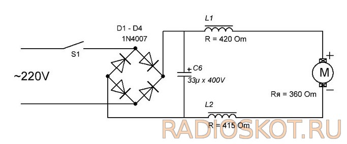
With tank for drilling boards - wiring diagram
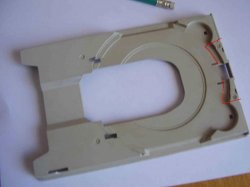
The basis of the entire frame and guides.
![]()
bushings, their inner diameter only one - two tenths of a millimeter more than the diameter of the guides, the material is ebonite (dielectric), not chosen by chance, this is a kind of "decoupling" from electric current. What the belt is made of, which later fixes the traction, is not difficult to guess.
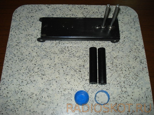
The button - switch is fixed on a plastic corner with 2 screws and nuts, the corner itself is connected to the bushings with glue.
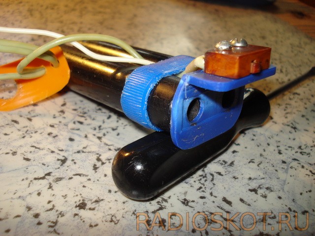
There is an M2 threaded hole in the motor shaft, it was not difficult to fit the collet. And the felt seals (on both sides of the shaft) waited for the oil.

As a "bearing" element, to which the engine is attached and which, in turn, is attached to the bushings, a furniture corner was chosen (light, durable and easy to process). Diode bridge and capacitor in a protective casing.

The stop consists of a spring, on one side of which the rubber stop itself is glued, on the other, a nut is soldered, which is screwed onto a screw that is mounted on a thread in the hole in the bed.

The drilling table is mounted on a screw (its additional function is described above).

And finally, how it all works:
Video of the drilling process
For those who liked it: everything from which this machine was assembled for, previously lay in cans, boxes and just corners. I think the hint is more than obvious. I wish your drills never get dull, Babay.
Discuss the article MACHINE FOR DRILLING PRINTED BOARDS


Chocolate biscuit: the secrets of cooking in a slow cooker and oven
Chemical composition and nutritional value
Apple chips at home
Braised cabbage with white beans, recipe
How to reduce the ass, hips and stomach at home?