- ......
[email protected]=MaxReal
[email protected]=MaxReal
[email protected]= MaxReal
[email protected]= MaxReal
OutBlock...
Make sure that the radius of the arc is specified by the Radius register name, in some post processors it's just R. I.e. parameter names must match the way they are listed in the register list.
Thus, all parameters of the arc will be displayed in the frame: G02/03 X__Y__R. You can even force a feed to be output in each frame by adding before OutBlock [email protected]=MaxReal
Don't forget to save the modified post processor.
What tells me if it was correct, then someone would not have screwed up the detail, if someone hadn’t screwed up the detail, then someone would not have addressed this question to the forum, as a result of which the whole crowd is arguing correctly or not. It seems to me that the phrase "dimensions and types should be arranged so that there is no double interpretation" means the following would be a drawing approximately like this, no one would have any questions. the author loaded the drawing with a bunch of unnecessary information and slipped the necessary information through ... some hole
For this you have to be afraid when you make and assemble. And after installation, they (walls) do not work for bending / for shearing, etc. These are purely guides. The walls should only prevent accidental "folding" of themselves.

You can select the desired one by brute force (when you move the cursor to such a place, a window with a choice proposal pops up), you can automatically delete all the "extra" ones, except for one - no. And so ... In AKAD there is a function "overkill", which is just for this purpose. Removes overlaps and merges collinear line segments and concentric identical arcs. NX works differently. Who knows what you used overlay curves for? If one is for pulling, the other for cutting, the third as a guide, then it will not be possible to delete without deleting dependent operations. And sometimes you will also need to project independent/imported curves into the sketch, without essentially changing their position. And again it turns out that you connect one with the other.
That is, this whole structure is supported by universal gravity, gradually occupying more and more space, outside of which there is nothing? This conclusion is logical from the big bang theory. But this theory is one of the versions of the formation of the universe, which suits many, but not all. And if we assume that the process of formation of universes is endless, and the basis is the matter of previous universes. But here the conflict is in the definitions.
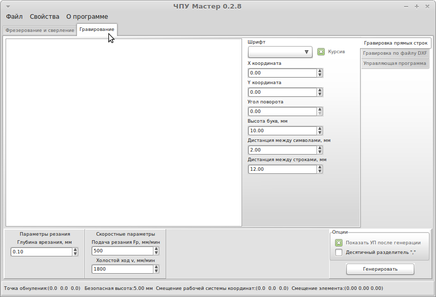
Starting from version 2.7.5.0, the CNC Master program supports working with DXF files, which can significantly reduce the complexity of writing many programs for controlling a CNC machine.
Writing a program for artistic engraving, both 3D and 2D, is a time-consuming task, the solution of which is extremely difficult without automation tools. For the case of 2D engraving, an image may consist of hundreds of thousands of primitives. Manually writing programs for such images would require considerable time. In case of preparation control program(hereinafter referred to as UE) using modern means processing information, this operation can take only a few minutes, taking into account the time to prepare the image file.
The algorithm for generating NC for 2D engraving using the CNC Master program is quite simple:
|
1. Run the program CNC Master (version 0.2.7.5 and older) |
|
2. Select the "Engraving" tab |
 |
 |
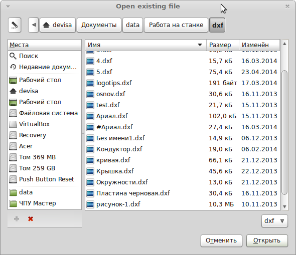
| 4. Click the "Load DXF" button, after which the file selection window will open |
 |
|
5. Select a pre-prepared file and click the "Open" button |
 |
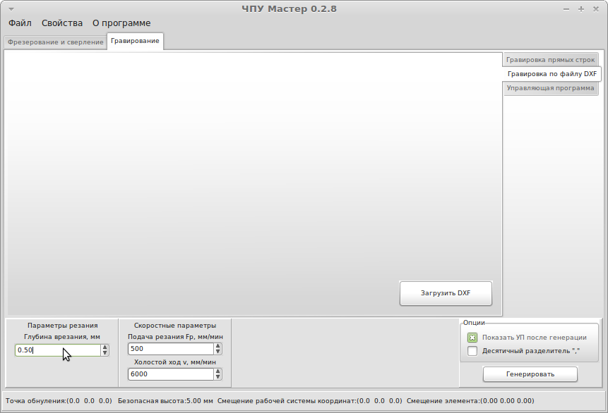
| 6. Set the engraving parameters (depth and speed) and click on the "Generate" button |
 |
|
7. After generation, the "Control program" tab will open with the result of generation |
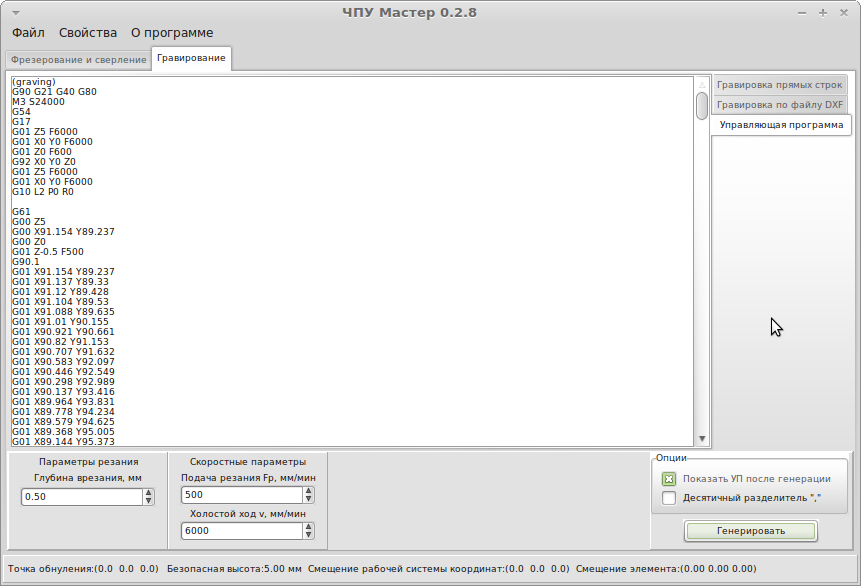 |
| 8. Select the "File" item in the top menu, then "Save", save |
 |
|
9. The program is ready. We load it into the machine control program and process it |
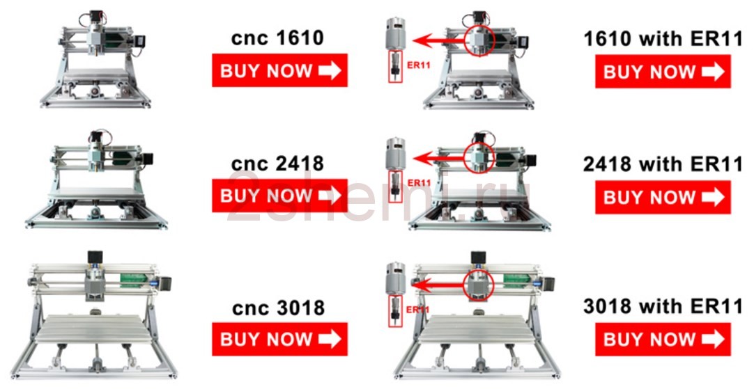
Have a small milling machine at home, and even with the possibility of laser engraving? Until recently, one could only dream of such a thing! And now such a pleasure is available for free sale on Chinese sites, at a price of $ 250 (15,000 rubles). And today the editors of the site "" have prepared a short review of such equipment. The machine can drill, mill, engrave, cut out windows and contours of workpieces from wood and metals. Naturally, not only with a cutter (on the motor), but also with a laser. Tool change is completed in a minute. Depending on the scope of delivery and the size of the working area, the cost varies markedly. For example, the junior model CNC 1610 GRBL with CNC, working area 16x10x4.5 cm, with a half-watt laser, can be bought for only $230 including shipping. In total, there are 3 main models: CNC 3018, 2418 and 1610 - these figures indicate the maximum size of the working area (working area). The machine itself is slightly larger. That is, 3018 stands for 30x18 centimeters.
Additionally, when buying, you need to indicate what power the laser needs. For example, a 2.5 W head itself costs under $100. But don't worry if you ordered a weak emitter - the site is full of lasers different capacities and they are all interchangeable, so buying and installing a new one is not a problem (for example, if you accidentally burned the old one).

Programs for CNC machines
Control software is standard for almost all machine models: GrblController and to create programs you need Artcam2008. With printed circuit boards (PCB) required coppercam. (not all sellers include this software in the delivery kit).

The beauty of these machines is that they come as do-it-yourself kits - the main components must be assembled by hand according to the instructions. Maybe someone will consider this work difficult, but any normal master will do it with interest and enthusiasm, and it will be useful for his son to participate in the process - after all, this is like a serious designer. Ready-made kits are also available.
Download instructions and programs
You can download all the necessary drivers, a control program with libraries in Russian and a set of instructions for using it from our server -
Specifications CNC 1610
- Dimensions: 260 x 240 x 220 mm
- Processed area: 160 x 100 x 30 mm
- Professional lead screws with backlash elimination
- Stepper motor: 42 steps
- Supply voltage: 12 V, current 1.3 A
- Torque 0.25 N.m
- Spindle: 775 motor (12-36V) 24V: 7000r/min, 36V: 9000r/min
- Laser installed: 500 MW
- Stepper motor power: 12V 3A
- Spindle motor power: 24V, 5A
- Table: 20100 profile (table size: 180 x 100 mm)
- The price of the kit with delivery: 10 thousand rubles.

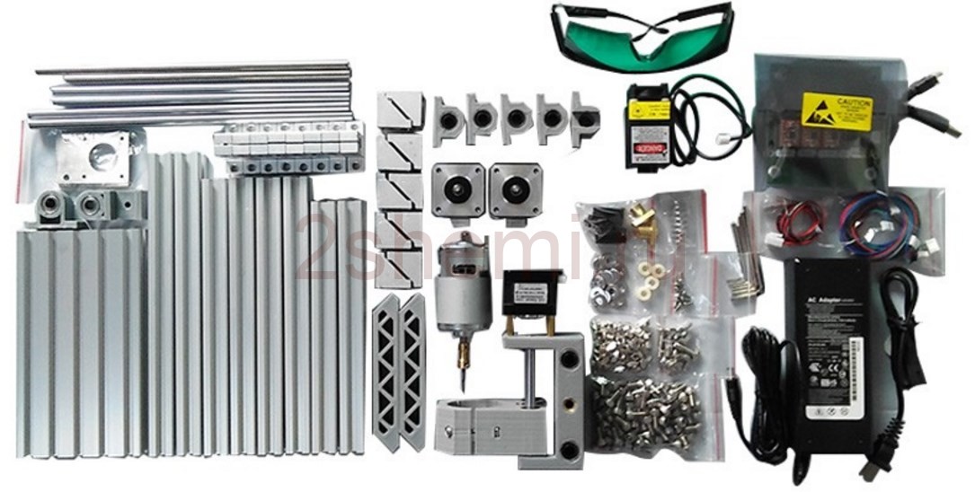
Package List
- 1 PC. CNC (full block)
- 4 things. fixtures
- 10 pieces. Engravers bits
- 1 PC. laser head
Depending on the desire of the buyer, almost everywhere you can change the configuration to the following options:
- All parts of the machine + 10 pcs. cutters (optional chuck ER11)
- All machine parts with 0.5W laser + 10pcs incisors + goggles
- All machine parts with 2.5W laser + 10pcs incisors + goggles
- All machine parts with 5.5W laser + 10pcs incisors + goggles

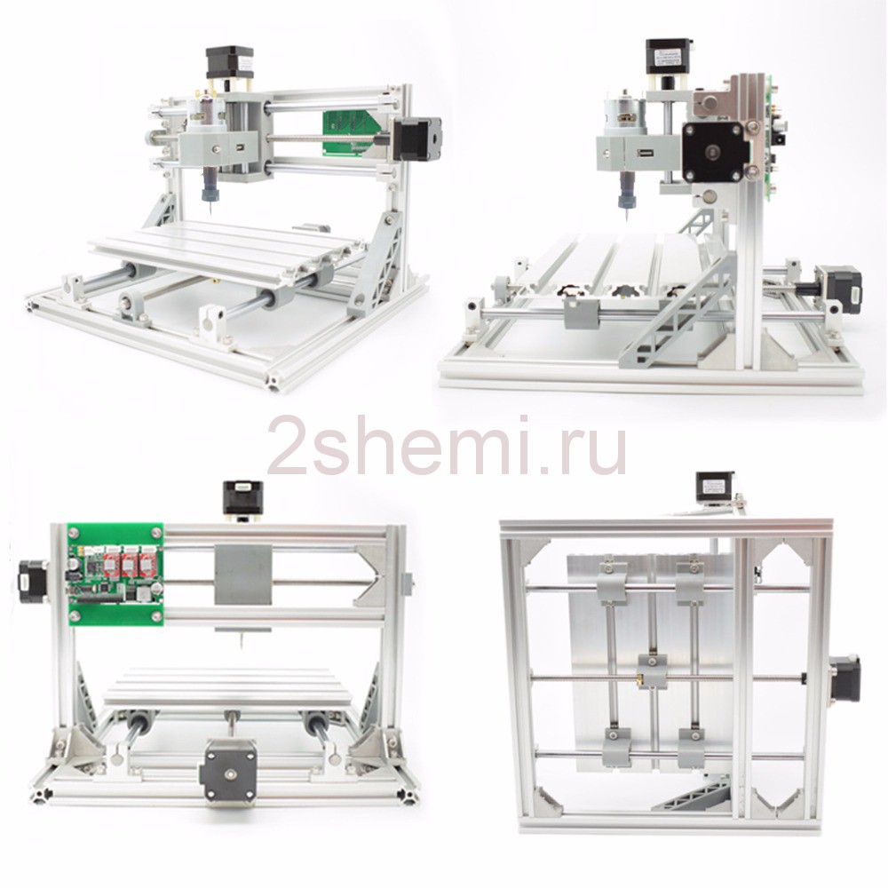
Specifications CNC 3018
- Machine overall size: 33x40x24 cm
- Working area: 30x18x4.5 cm
- Spindle drive: 775 motor (12-36V) 24V: 10000r/min
- Spindle chuck: ER11 collet
- Stepper motor: 34mm, current 1.3A, 12V. Torque 0.25 N/m
- Power supply: 24 V, 6 A
- Software: GrblController
- Supported system: Windows (not support Mac)
- Milling tool included: tip 0.1 mm, 20 degrees, D=3 mm. Pack of 10
- Choice of lasers: 12V/500mW 405nm, 12V/2500mW 450nm, 12V/5500mW 450nm
- Clips: 4 pieces, thickness 0-30mm, size: 50x20x12 (length x width x thickness), inner width 8mm
- The price of the maximum set with delivery: 20 thousand rubles.

Pay attention to the type of cartridge. It must be necessarily collet ER11. No need to save $10 on this as the convenience of it is obvious!
We will not give links to any sites and sellers, so as not to be accused of excessive advertising - through a search on Aliexpress, you can find it yourself on request: CNC-3018 ER11 grbl DIY CNC Router 3 Axis Laser Engraving Milling Machine.
Electrical connection diagram
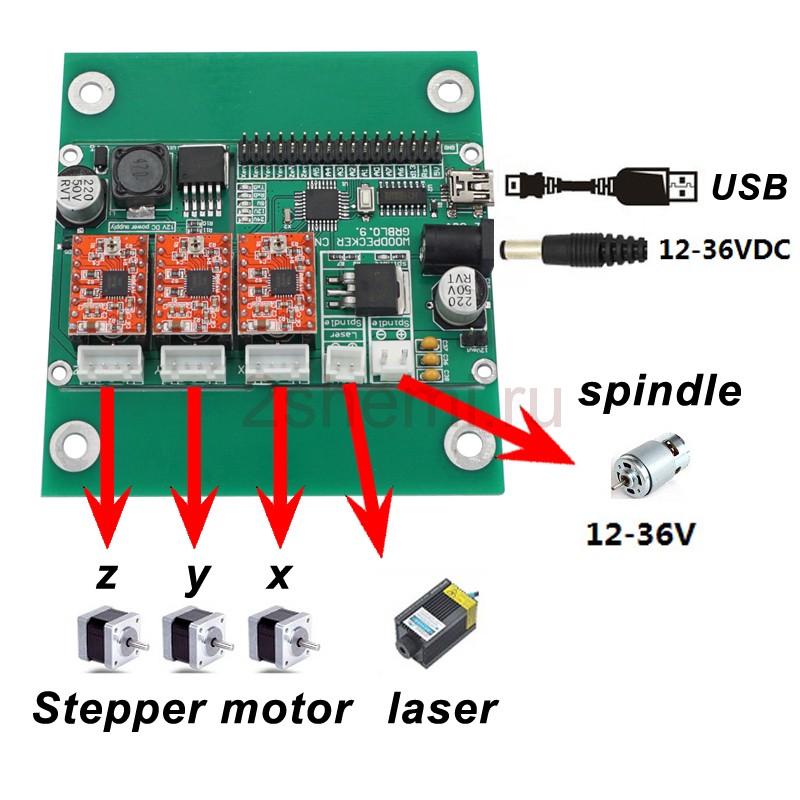
All electronics fit on one printed circuit board to which are connected stepper motors axes and spindle motor, as well as a 12 volt laser head. PC connection via wired USB interface.
Customer Reviews
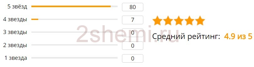
Great machine, very fast delivery, everything works! I ordered a machine with a laser 5500. The seller sent a laser for 500 by mistake. Without opening a dispute, he sent me a new laser for 5500, which arrived within 2 weeks complete with one more glasses and a very good case (a laser for 500 is just a seller for me donated)! Many thanks to the seller for the excellent quality of the goods and such an attitude!
Fast delivery, everything is well packed. True, the marking of 400-450nm is indicated on the laser. How can this be understood? I only need 405nm for the photoresist, which I warned the seller about. In reality, the photoresist has not been illuminated yet, so I can’t say what wavelength the laser has, and what shape of the point when focusing, round or rectangular. In extreme cases, you will have to replace the laser module with 405 nm.
The package is well packed. Thick cardboard, completely wrapped with yellow tape. Everything inside is lined with polyethylene foam. All elements in separate niches. All the details look well done. Traditionally, there is no instruction. Collected from photos from the seller's website and examples from YouTube. There were no special problems with the assembly. The mechanical and electrical parts are ready, the software is ahead.
Sending from Russia, it came quickly enough. The hands have not yet reached the laser, I assembled the frame with the engines and checked them for operability. The engine mounting plate for the spindle carriage had to be bored, because. there was a terrible misalignment in the coupling between the engine and the worm shaft. Designer, what can I say 🙂 I had to buy longer bolts under the table, because from the kit, the bolts are screwed on a couple of turns. There had to put washers to eliminate wedging. In general, for its price is more than normal. It is necessary to buy limit switches for extreme positions, because I feel that while I get used to the software and the machine, I will hit the motors, or the motors will bend the frame 🙂 There are inputs for them on the control board, Google is aware 🙂 Only 2 cutters were put in the kit, opened a dispute, and the seller sent a set of 10 cutters. In general, it’s fine, I didn’t pull the rubber 🙂 I deservedly received 5 stars.
Using the machine - video
The machine can be used to cut or engrave plastic, wood, solid metal, acrylic, pvc, pcb, wood or other similar material. From experience, we note that 0.5 watts is extremely small - with such a beam, only burn drawings on wood, cardboard and plastic. If you want to work with metal, you need at least 5 watts. Not for cutting, but engraving. See clearly on YouTube video.
Summarize
Compact size, rugged body profile, light weight, USB interface, GRBL control system, works with various lasers. Interchangeable standard parts, many positive feedback and affordable price. And most importantly - the ability to significantly simplify the manufacture of various improvised designs, allowing you to come close in quality to factory products.
CNC milling and engraving machines excellent not only for cutting and processing materials, but also for applying a clear engraving pattern to the surface of the workpiece various types. The capabilities of the CNC system make it possible to use graphic sketches of any kind and almost any complexity as the basis for the processing program. At the same time, the cutting tool, which has three degrees of freedom even in the "budget" models of milling machines, can accurately transfer the pattern base sketch on the surface of the workpiece - both flat and curved.
A complex pattern can be used as a pattern for engraving. volumetric 3D sketch. In this case, the task for the milling machine is the exact embodiment “in the material” of all the features and details of the pattern in order to create a realistic three-dimensional relief on the machined surface. However, not every workpiece material lends itself to high-quality engraving. The end result will largely depend on right choice cutting tool (milling cutter or engraver), processing modes and technological transitions.
When it comes to engraving complex relief– processing sequence separate parts(central area, peripheral details, background, etc.) has a decisive influence on the quality of the finished product. This means that the processing program, which includes all the initial information for processing, must be created with special care and understanding of the features of the engraving process.
Basic algorithm for creating a control program
To engrave complex (volumetric) reliefs, a control program is required. Its creation is no different from the development of similar programs for processing on milling machine with CNC. A typical sequence of actions looks like this:
1. A sketch (image) is selected for future engraving. It can be either a finished 2D drawing or an original designer's sketch. The main thing is that the sketch should be in digital form (preferably vector, but it is also possible to work with a raster sketch).
2. Based on the selected sketch, a 3D model is created (it is also sometimes called a "relief").
* In the case of using ready-made 3D models from the extensive libraries currently available, points 1 and 2 are skipped.
3. The 3D model is imported into the CAM application (for example, " artcam"). For a newly created project, the size of the engraving, its location/orientation on the workpiece surface, and a number of other auxiliary parameters are indicated.
4. On the basis of the obtained model, the trajectory of the cutting tool is built: the processing area for each technological transition is indicated, the type of tool (cutter or engraver) is selected, its dimensions and cutting modes are set.
5. The processing visualization procedure starts.
* This utility will allow you to carry out "virtual milling" to evaluate the finished result (on a computer screen), identify errors and promptly eliminate them.
6. The control program is saved using a special postprocessor (corresponding to a specific type of milling machine).
* The saved file must have only numeric or Latin characters in the name.
7. The finished file of the control program is loaded into the CNC memory of the milling machine and the production of a trial engraving sample is started.
Ideally, the engraving result on CNC milling machine must fully comply with the original sketch and meet the quality requirements (accuracy and cleanliness of processing). However, in practice, the test sample often turns out to be corrupted - even if there are no external errors in the control program.
elimination possible errors control program
To ensure a high-quality engraving result of complex reliefs, the coordinated action of the "mechanical" and "electronic" parts of the milling machine is necessary. This means that a correctly written control program must necessarily be combined with a competent choice. cutting tool(engraver), as well as the correct placement and fixing of the workpiece and the precise positioning of the tool at the starting point of processing. At the same time, in order to save the material of the workpiece, electricity and the life of the machine as a whole, it is desirable to eliminate most of the discrepancy errors at the stage of machining simulation - without milling a large number trial products.
Typical errors in the control program may be as follows. Firstly, the intersection of vectors. This is the most common mistake caused by the “contamination” of the original drawing, on the basis of which the 3D model is built, with small, mutually intersecting and superimposed vectors. Such a picture is sometimes very difficult to distinguish visually - even with maximum magnification images on the monitor. However, to solve the problem, there is no other way but to manually "clean" the original sketch from unnecessary segment vectors. To simplify this procedure, you can try to stroke the path with a new vector on top of the existing drawing. This, however, is only possible for relatively simple sketches that do not contain a large number of elements (for example, you cannot draw a portrait or an icon again!). It should be noted that ready-made models for processing (both freely distributed on the net and, all the more so, custom-made) are usually free from such shortcomings. When choosing finished models, it is recommended to give preference to those for which samples were successfully made by other operators by fellow operators.
Secondly, it is necessary to specify the engraving area correctly. For complex terrain, you may need an additional vector that limits the entire processing area along the perimeter (a kind of "frame"). Otherwise, the program will perceive the relief as scattered flat segments.
Thirdly, to obtain high-quality engraving, a clear binding of the tool in height (Z coordinate) is necessary. Otherwise, excessive (or insufficient) depth when processing with a V-shaped engraver will lead to relief errors. To precisely set the spindle above the workpiece (at the zero point of processing), you can use measuring gauges. Alternatively, a car gap gauge is suitable. It is also necessary to clearly set the angles of the cutting tool in the control program - and monitor their actual state (no wear or scrap of the tool).


Mixed Personality Disorder: Causes, Symptoms, Types and Treatments
GTA 4 control settings
FAQ on Smuggling in GTA Online
LSPDFR - welcome to the police
The huge map of Grand Theft Auto San Andreas and its secrets