1.doc
^1. Numerical control (CNC)
1.1. CNC machine tool
1.1.1. Motion executive bodies machine tool
For processing workpieces on CNC machines, as well as on universal machines, it is necessary to inform the cutting tool and the workpiece of a certain, usually quite complex, set of movements coordinated with each other. These movements are divided into main(working) and auxiliary.
^ Basic movements - these are the movements of the executive bodies of the machine, due to which the process of removing chips with a cutting tool from the workpiece is directly carried out. The main movements are main movement and innings movement.
^ Main motion determines the speed of the cutting process. It is defined as the rectilinear translational or rotational movement of the workpiece, occurring at the highest speed during the cutting process. In turning, this movement is the rotational movement of the workpiece. In milling, as well as in drilling and boring work, the rotational movement of the cutting tool.
^ Movement of innings determines the magnitude, speed and nature of the mutual movement of the tool and the workpiece, designed to spread the separation of the cut material layer over the entire surface of the workpiece being machined. The movement of the feeds may be straight or in an arc, continuous or intermittent, and it always has a speed less than the main movement. In turning, the movement of the feeds is the movement of the support with the cutting tool. During milling and boring work- movement of the work table with the workpiece, during drilling work - movement of the quill, etc.
^ Auxiliary movements - these are the movements of the executive bodies of the machine and fixtures necessary to prepare the cutting process. These include movements associated with the transportation and fixing of the workpiece, the approach and withdrawal of the cutting tool, etc.
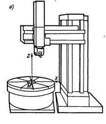
The number, nature and directions of movements of the executive bodies during the movement of feeds for CNC machines and universal machines, as a rule, coincide. For example, CNC lathes (see Fig. 1-A), as well as universal lathes, have feed movement in at least two directions in the form of rectilinear movements of the executive bodies (shown in the figure with bold arrows).
CNC milling machines, as well as universal milling machines, have feed movement in at least three directions in the form of rectilinear movements of the executive bodies (see Fig. 1-B).

In more complex modifications of milling machines, in addition to rectilinear movements of the executive bodies, circular movements are also added, performed around the axes of rectilinear movements (see Fig. 1-B). The number of additional circular movements may be different, depending on the complexity of the machine. Most often, the number of circular movements does not exceed three.
Rice. 1-B. Additional circular feed directions
CNC milling machine
^
1.1.2. CNC Machine Coordinate Systems
The processing of the workpiece on a CNC machine is carried out according to the commands of the control program, which numerically set the values of individual movements of the executive bodies. Therefore, the operation of a CNC machine is in principle impossible without the use of a certain coordinate system, with the help of which the spatial coordinates of any point within the working area of the machine are set.
In CNC machines, two types of coordinate systems are most commonly used:
rectangular.
polar.
The rectangular coordinate system is the most common coordinate system for CNC machines. It contains either two coordinate axes (two-dimensional system) - to determine the position of points on the plane, or three axes (three-dimensional system) - to determine the position of points in space.
For a rectangular coordinate system, the following features are characteristic:
coordinate axes are mutually perpendicular;
coordinate axes have a common point of intersection (origin of coordinates);
coordinate axes have the same geometric scale.

Rice. 1.1. Rectangular coordinate system on the XY plane
P1: X=80, Y=40; P2: X = -80, Y = 70; P3: X = -50, Y = -40; P4: X=40, Y=-70.
With the help of a spatial rectangular coordinate system, the position of any points in the geometric space is described. To determine the position of any point in space, you need to know its coordinates along three axes - X, Y and Z (Fig. 1.2). As in the case of a flat coordinate system, the values of the coordinates of points in space can have both positive and negative values. This coordinate system allows you to describe all points of the working space of the machine, regardless of the location of the workpiece and is used in CNC milling, drilling and boring machines.
Rice. 1.2. Spatial rectangular coordinate system
An example of the designation of the coordinates of the points indicated in the figure:
P1: X=30, Y=20, Z=0; P2: X=30, Y=0, Z=-10.
The spatial rectangular coordinate system adopted for CNC machines has a certain orientation of the coordinate axes relative to each other. This orientation is subject to the rule right hand(see Fig. 1.3), in which the fingers of the right hand indicate the positive direction of each axis. Therefore, this coordinate system is called the right system.

Rice. 1.3. Right hand rule
^
Polar coordinate system
If the processed contour is a broken line, then with the help of a rectangular coordinate system, you can easily set all the characteristic points of its profile. However, the situation changes if it is necessary, for example, to drill a group of holes arranged along a circle on a plane (see Fig. 1.4). If for hole 1 the coordinates of the location of its axis in a rectangular coordinate system can be calculated quite simply, then the calculation of the location of the axes for all other holes will be much more laborious.

Rice. 1.4. Detail with a group of holes arranged in a circle
V  In this case, it is more convenient to perform calculations in the polar coordinate system (see Fig. 25 and Fig. 26). In the polar coordinate system, the position of a point on a plane is determined by the distance (radius) r from the point to the origin and the angle
between a certain coordinate axis and a radius drawn to a point from the origin. As a rule, in the polar coordinate system on the XY plane, the angle
indicated from the x-axis. Angle
can have both positive and negative values. Positive value - if it is plotted in the direction opposite to the clockwise movement from the area of positive coordinate values along the X axis (Fig. 1.5-A); negative value - if it is plotted in the clockwise direction from the area of positive coordinate values along the X axis (Fig. 1.5-B).
In this case, it is more convenient to perform calculations in the polar coordinate system (see Fig. 25 and Fig. 26). In the polar coordinate system, the position of a point on a plane is determined by the distance (radius) r from the point to the origin and the angle
between a certain coordinate axis and a radius drawn to a point from the origin. As a rule, in the polar coordinate system on the XY plane, the angle
indicated from the x-axis. Angle
can have both positive and negative values. Positive value - if it is plotted in the direction opposite to the clockwise movement from the area of positive coordinate values along the X axis (Fig. 1.5-A); negative value - if it is plotted in the clockwise direction from the area of positive coordinate values along the X axis (Fig. 1.5-B).

Rice. 1.5. Positive (A) and negative (B) angle values
In the polar coordinate system.
Additional rotary coordinate axes
Despite the fact that with the help of a 3-coordinate rectangular coordinate system the position of any points in the geometric space is described, in modern machining it often becomes necessary to manufacture such complex surfaces that they cannot be made on a machine using the movement of the executive bodies only along three coordinate axes.In such situations, a spatial rectangular coordinate system with additional coordinate axes is used. Additional coordinate axes are rotary axes that are located around the main linear axes X, Y and Z (see Fig. 1.6). The axis of rotation around the X-axis is referred to as the A-axis, the axis of rotation around the Y-axis as the B-axis, and the axis of rotation around the Z-axis as the C-axis.
The coordinates along the rotary axes can also have both positive and negative values. The positive direction (from "minus" to "plus") of the rotary coordinate axis is taken to be clockwise, if you look at the axis of rotation in the positive direction of the corresponding linear axis.
Rice. 1.6. Rectangular coordinate system with additional rotary axes.
A rectangular coordinate system with additional rotary axes can also be represented as a spatial polar coordinate system (see Fig. 1.7).

Rice. 1.7. Spatial polar coordinate system
CNC machine coordinate system
For CNC machines, a single coordinate system recommended by the International Organization for Standardization (ISO) has been adopted - a rectangular coordinate system. The number of coordinate axes, their location in space and the origin (zero point of the machine) are set by the machine manufacturer and cannot be changed by the user (see Fig. 29). The machine coordinate system is the main calculation system for the CNC, in which the limit displacements, initial and current positions of the machine's executive bodies are determined.For the convenience of programming the processing process in CNC machines, it is customary to always orient the coordinate axes parallel to the guides of the machine. Depending on the type of machine, the location of the coordinate axes in space may be different, but there are the following general rules.
1. The Z axis is always aligned with the axis of rotation of the spindle. Its positive direction always coincides with the direction of movement from the workpiece clamping device to the cutting tool.
2. If there is at least one axis in the machine coordinate system that is horizontal and does not coincide with the axis of rotation of the spindle, then this will necessarily be the X axis.
3. If the Z-axis is horizontal, then the positive direction of the X-axis is the direction of movement to the right, if you stand facing the left - relative to the front plane - the end of the machine. (The front plane of the machine is the side on which the console and the main controls of the machine are located).
4. If the Z-axis is vertical, then the positive direction of the X-axis is the direction of movement to the right, if you stand facing the front plane of the machine.
5. The positive direction of the Y-axis is determined by one of the following rules:
– Looking along the Z-axis in a positive direction, mentally rotate the X-axis 90° clockwise around the Z-axis.
– Rule of the right hand: if you mentally place the palm of your right hand at the origin in such a way that the Z axis comes out of the palm perpendicular to it, and the thumb bent at an angle of 90 ° to the palm shows the positive direction of the X axis, then the index finger will show the positive direction of the axis Y.
^ Workpiece coordinate system
The workpiece coordinate system is set by a technologist or programmer when developing a technology for manufacturing a part on a CNC machine (see Fig. 1.8). The starting point, from which the CNC system counts the movements of the executive bodies of the machine when processing the workpiece according to the control program, is called the zero point of the workpiece. The workpiece zero point has no fixed coordinates. Each time you change the configuration and dimensions of the workpiece, the zero point of the workpiece is assigned anew - depending on the configuration of the part, the processing technology and the convenience of setting up the machine.

Rice. 1.8. Coordinate systems of the machine (A) and workpiece (B).
Recommended Workpiece Coordinate System for Milling
Extensive CNC milling capabilities allow you to use the most different systems workpiece coordinates. Based on the design features of milling machines and the actual milling process, the following coordinate system is usually recommended, which is equally convenient for programming and processing.This workpiece coordinate system is a rectangular coordinate system with XYZ axes (see Figure 1.9). The Z axis of this system coincides with the axis of the main work spindle of the milling machine, while the positive direction of the axis is the direction from the workpiece to the clamping point of the tool in the spindle.
If the workpiece has a plan rectangular shape, then the X and Y axes coincide with the sides of the workpiece. If the workpiece has a shape other than rectangular in plan, then either the X-axis or the Y-axis is located on one of the sides of the workpiece. In this case, when viewed from the side of the front plane of the machine, the positive direction of the X axis goes from left to right, and the Y axis - from the front plane of the machine.
To facilitate the calculation of coordinates when compiling a program, a point on one of the outer corners of the workpiece contour is usually selected as the origin of the workpiece coordinate system (workpiece zero point).
^ Recommended Workpiece Coordinate System for Turning
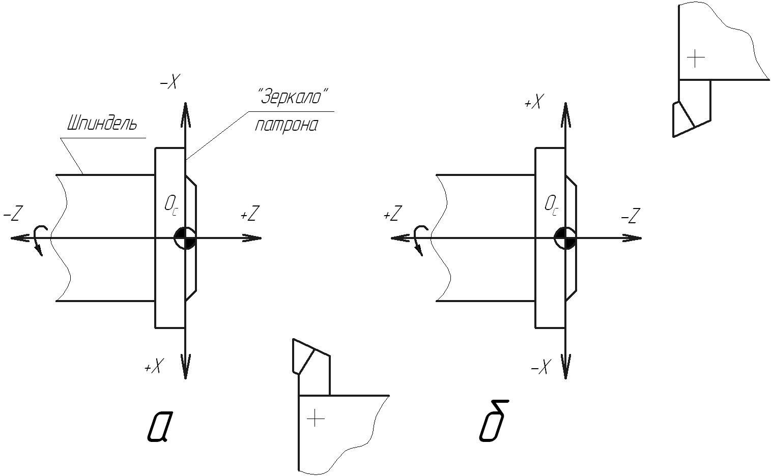
For turning on a CNC machine, the most common is a flat rectangular workpiece coordinate system, the axes of which are usually called X and Z. In this system, the Z-axis is the axis of the main spindle of the machine, while the positive direction of the Z-axis is the direction from the place where the workpiece is held in the spindle to cutting tool. The X-axis is perpendicular to the Z-axis, and its positive direction depends on the position of the tool relative to the Z-axis (see Fig. 1.10). But in any case, the positive direction of the X-axis is the movement at which the tool moves away from the workpiece.

Rice. 1.10. The workpiece coordinate system in turning, in which the tool is directed to the axis of rotation from the front plane of the machine (A), and in which the tool is directed to the axis of rotation towards the front plane of the machine (B).
^
1.1.4. Position and designation of coordinate axes in CNC machines
According to technological features and capabilities, CNC machines are classified into groups in the same way as universal machines. In this case, depending on the layout of the CNC machine, the type and spatial arrangement of its coordinate system changes.
CNC milling machines use a spatial coordinate system, usually rectangular. The determining factor for the spatial arrangement of the axes of the coordinate system is the spatial orientation of the axis of the work spindle. The spindle axis of the milling machine always coincides with the Z-axis. The positive direction of the Z-axis is the direction from the workpiece attachment on the work table to the cutting tool attachment in the spindle. If the Z-axis (spindle axis) is vertical, then such a machine is a vertical milling machine, if the Z-axis is horizontal, then it is a horizontal milling machine.
The spatial location and positive direction of the other two main coordinate axes X and Y is determined in accordance with the “right hand rule” (see 1.3). If the CNC milling machine coordinate system contains more than three axes, then the location of additional coordinate axes is determined by the location of the main axes (see Fig. 1.6).

Rice. 1.11. Vertical milling machine coordinate system (A)
And a horizontal milling machine (B).
For CNC lathes, the most common is a flat rectangular coordinate system with Z and X axes. As with milling machines, the determining factor for the spatial arrangement of the axes of the coordinate system is the spatial orientation of the axis of the work spindle, which always coincides with the Z axis. The Z axis is the direction from where the workpiece is held in the spindle to the cutting tool. The X axis is located perpendicular to the Z axis, while the positive direction of the X axis coincides with the direction of movement, in which the tool moves away from the workpiece (see Fig. 1.12).


Rice. 1.12. . Coordinate system lathe with horizontal (A) and vertical (B) spindle arrangement.
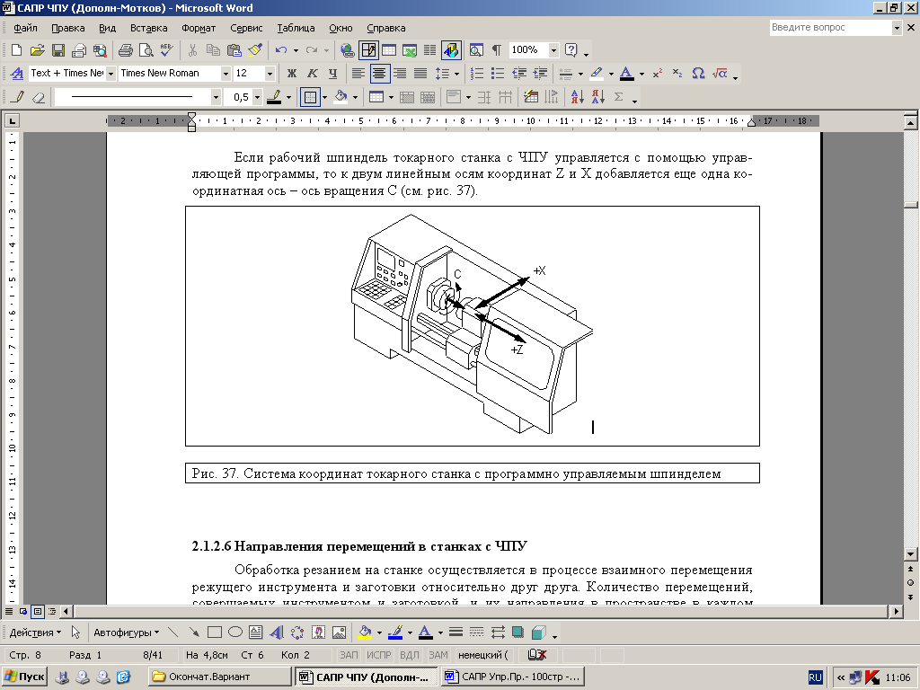
If the working spindle of a CNC lathe is controlled using a control program, then one more coordinate axis is added to the two linear coordinate axes Z and X - the axis of rotation C (see Fig. 1.13).
^
Directions of movement in CNC machines
Machining by cutting on the machine is carried out in the process of mutual movement of the cutting tool and the workpiece relative to each other. The number of movements made by the tool and the workpiece, and their directions in space in each case depend on the type of processing and machine design. For example, when machining on a vertical milling machine, the workpiece actually moves along the horizontal X axis and vertical Z axis, and the tool moves along the horizontal Y axis. When machining on a horizontal milling machine, the workpiece moves along the horizontal X axis and vertical Y axis, and the tool - along the horizontal Z axis. As a result, the descriptions of the movements of the executive bodies for machines of different designs when processing the same workpiece have different kind.
In order for the description of the direction and type of movement of the executive bodies of the machine to have the same form for machines of different designs, it is accepted universal rule for CNC machines: it is considered that in the process of processing all movements are made only by the tool, and the workpiece remains motionless.
For CNC machines, another universal rule has been adopted regarding the direction of movement of the executive bodies. This rule, unlike the first one, is not obligatory, but advisory in nature: it is desirable to coordinate the coordinate systems of the machine and the workpiece in such a way that as many coordinate axes of the workpiece fixed on the machine coincide or be parallel to the coordinate system of the machine. Usually, in this case, the complexity of compiling a control program is minimal, since when compiling the program, the coordinates of the workpiece points already on the drawing are used. In turn, minimization and simplification of the control program leads to a decrease in the probability of an error occurring when compiling the program.
In modern CNC machines, two methods of counting the movements of the executive bodies of the machine are used - in absolute and relative coordinate systems.
In the absolute coordinate system, all movements performed by the machine are specified in such a coordinate system, the origin of which remains unchanged for all movements (see Fig. 38). As a constant (fixed) origin, a certain point in space, which lies in the area of movement of the executive bodies of the machine, is preselected. As a rule, the zero point of the workpiece is selected as this.
In the relative coordinate system, each movement of the executive bodies of the machine is specified relative to the end point of the last movement, i.e., it is specified in increments (see Fig. 1.14).

Rice. 1.14. Counting of displacements in absolute (A) and relative coordinate systems.
More common is the method of counting displacements in an absolute coordinate system. This is due to the fact that in the general case it has a number of advantages, namely:
calculations in the absolute coordinate system are less complex and require less high qualification of the operator;
an indication from the same origin of the path traversed by the cutting tool makes it easier to track the stages of the implementation of the control program;
an error when programming in an absolute coordinate system leads to an incorrect assignment of the coordinates of only one point, while as a result of an error when assigning relative coordinates, not only a specific incorrectly specified movement, but also all subsequent movements after it will be erroneous;
changes to movements made during the finalization of a product or program do not affect subsequent movements;
manufacturing and measurement errors that lie within the permissible limits are not accumulated (not summed up).
The operation of a CNC machine is closely related to coordinate systems. The coordinate axes are parallel to the guides of the machine, which allows you to indicate the direction and magnitude of movement of the working bodies when programming the processing. As a single coordinate system for all CNC machines, in accordance with GOST 23597-79 * (ST SEV 3135-81), a standard (right) system is adopted, in which the axes X, Y, Z (Fig. 14.19) indicate the positive movement of the tools relative to the moving parts of the machine. Positive directions of movement of the workpiece relative to the fixed
machine parts indicate axis X", Y′, Z", directed opposite to the axes X, Y, Z. Thus, positive movements are always those in which the tool and the workpiece move away from each other.
Circular movements of the tool (for example, angular displacement of the spindle axis of a milling machine) are indicated by letters A (around axis X ), V (around axis Y ), WITH (around axis Z ), and circular movements of the workpiece (for example, program-controlled rotation of the table by boring machine) - respectively letters A ′, B", C ′. The concept of "circular movements" does not include the rotation of the spindle carrying the tool, or
lathe spindle. To designate
Rice. 14.19. Standard system secondary angular movements around special
coordinates of CNC machines axes use letters D and E . To designate
the directions of movement of two working bodies along one straight line use the so-called secondary axes: U (parallel X ), V (parallel At ), W (parallel Z ). With three movements in one direction, the so-called tertiary axes are also used: P, Q, R (see fig. 14.19).
Machine coordinate system. At the machines various types and models of the coordinate system are placed differently (Fig. 14.20), while determining the positive directions of the axes and the position of the origin (machine zero M ).
The machine coordinate system is the main calculation system in which limit displacements, initial and current positions of the machine tools are determined. At the same time, the positions of the working bodies of the machine characterize their base points, selected taking into account design features individual program-controlled units of the machine. So, the base points are: for the spindle assembly - the point N intersection of the end of the spindle with the axis of its rotation (Fig. 14.21); for the support of a turret lathe - the center of rotation of the tool holder in a plane parallel to the guides of the support and passing through the axis of rotation of the spindle, or the basing point of the tool block; for a cross table - the point of intersection of its diagonals or a special tuning point determined by the design of the fixture; for a turntable - the center of rotation on the mirror of the table, etc.
The reference point can be tangibly represented by an exact reference hole in the center of the machine table (for example, point F in fig. 14.21).
In the technical documentation, the limits of possible displacements of the working bodies, as a rule, are indicated by the limits of the displacement of the base points.
The coordinate system of the machine, selected in accordance with the recommendations of GOST 23597-79 * (see Fig. 14.19), is usually called standard. In this system, the positive directions of the coordinate axes are determined by the right-hand rule. Thumb (Fig. 14.22, a) indicates the positive direction of the x-axis ( X ), index - ordinate - ( Y ), middle - applicate axis ( Z ). The positive directions of rotation around these axes are determined by another right-hand rule. According to this rule, if the thumb is placed in the direction of the axis, then the remaining bent fingers will indicate a positive direction of rotation (Fig. 14.22, 6).
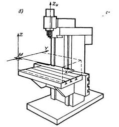
Rice. 14.20. Placement of coordinate systems for various CNC machines:
a - carousel; b- vertical milling
The orientation of the axes of the standard machine coordinate system is associated with the direction of movement when drilling on drilling, boring, milling and turning machines. The direction of withdrawal of the drill from the workpiece is taken as positive for the axis
Rice. 14.21. CNC vertical drilling machine coordinate system
Z, i.e. axis Z always associated with the rotating element of the machine - the spindle. Axis X perpendicular to the axis Z and parallel to the workpiece installation plane. If two axes correspond to this definition, then for the axis X take the one along which the greatest possible movement of the machine unit. With known axes X and Z axis At is uniquely determined from the condition of the location of the axes in the right rectangular coordinate system.
The beginning of the standard coordinate system of the machine is usually combined with the base point of the node that carries the workpiece, fixed in such a position in which all movements of the working bodies of the machine could be described by positive coordinates (see Fig. 14.20, 14.21). Dot M , taken as the origin of the machine coordinate system, is called the machine zero point or machine zero. In this position, the working bodies (base points) that carry the workpiece and the tool have the smallest distance from each other, and the reading elements of the machine determine the zero of the reading on the digital display board.
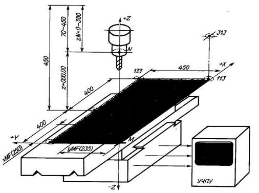
For example, for a vertical drilling machine (see Fig. 14.21), the base point F table is the center of the table, in which a hole with a diameter of 40H8 is made. The spindle base point is the point N- the center of the spindle hole in the plane of the spindle nose. The design of the machine determines that the table can move along the axis X(longitudinal axis of the table) 400 mm to the right and left of the center position of the reference point. Possible offsets
axis table At(transverse) are 450 mm. Thus, the rectangle (shaded in Fig. 2.4) formed by the lines of the possible displacement of the point F along the axes X and Y, determines the possible zone for processing workpieces with a tool, the axis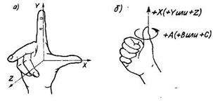 which coincides with the spindle axis. This zone (it is often called the working zone) of the considered machine in the plane is limited by the dimensions of 800X450 mm.
Availability of data on the processing area
Rice. 14.22. Right hand rule; necessarily, since they determine the
a- positive directions machine capabilities when programming
coordinate axes; b– positive movement of workpieces.
directions of rotation In order to count_displacements
tables along the axes X and Y has always been the positive zero of the machine M accept placed in one of the corners of the working area (see Fig.
14.20, b). Naturally, the position of the point M is fixed_and unchanging, in which case the point M will be the machine origin. Then the position of the point F can be given coordinates xMF and yMF relative to the point M .
For the machine in question (see Fig. 14.21), the position of the point F will vary within 0-800 mm along the axis X and 0-450 mm along the axis At. Possible displacement of the spindle nose in the direction of the axis Z will be 380 mm (70 - 450 mm). In this case, the lower (limit) position of the end face relative to the table mirror is taken as the beginning of the movement, at which the distance from the end face to the table mirror is 70 mm.
![]() When the machine is operating, the indication board on the CNC panel reflects the true position of the machine base points relative to the machine zero.
When the machine is operating, the indication board on the CNC panel reflects the true position of the machine base points relative to the machine zero.
For the example under consideration, this is the position of the point F relative to the point M and points N relative to the zero level in the corresponding system XYZ machine coordinates. For the mutual position of the working bodies of the machine shown in fig. 14.21, the display will show the data: X250.00, Y235.00 and Z000.00. For the position where the spindle axis is aligned with point 133, the display will show X800.00, Y450.00 and Z000.00. in a position where the dot N will be aligned with point 313, the display will show the following values: X800.00, Y000.00 and
Rice. 14.23. Coordinate systems Z380.00, etc. On the machine in question, in the position
machine tool (XMY) and workpiece (X U WY A when the spindle axis is aligned with the zero point M,
PARTS ON CNC LATHES
1.1. Development of a control program and technological
documentation
The process of developing a control program (programming) for a CNC lathe consists of several stages:
The operation is divided into installations and positions, the technological bases and the method of fixing the workpiece are selected;
They develop operating technology, determine the sequence of transitions, select technological equipment, cutting and measuring tools, build diagrams of trajectories for moving the top of each tool used, calculate cutting modes, develop operating maps;
Transform the coordinate system of the part and select its zero point, calculate and put down the dimensions of the part from the zero point;
Sketch maps are developed, on which a revised drawing of the part is given with the specification of dimensions from the zero point and the symbol of technological bases and clamps (Fig. 1), constructions for calculating the coordinates of reference points, calculations for determining their coordinates, trajectory schemes (cyclograms) of the movement of all tools . Symbols of elements of cyclograms on maps of sketches are given in fig. 2. For auxiliary moves, conditional terminology is used: movement to the part along the X axis - approach; movement from the part along the X axis - retraction; movement to the part along the Z axis - approach; movement away from the part along the Z axis - withdrawal. Maps of the coordinates of the reference points of the trajectory are made, and when programming in a relative system - the magnitude of the increments;
Compose a manuscript of the control program on a form or frame-by-frame text on a sheet of paper. Using the keyboard of the control panel of the CNC 2P22 system, enter control program in the memory of the CNC system;
The control program is checked on the machine and, if necessary, make appropriate adjustments.
Rice. one. Conventional designation of technological bases and clamps:
a- fastening in a three-jaw chuck with an emphasis on the bored end of the jaws, b- fastening in a three-jaw chuck with an emphasis on the end of the jaws, v- fastening in a three-jaw chuck with an emphasis on the bored end of the jaws and the rear rotating center, G– fastening in the front floating center, driving chuck and rear rotating center, d- fastening in the front leash friction "glass" and the rear reverse rotating center, e- fastening in the front leash "ruff" and the rear rotating center
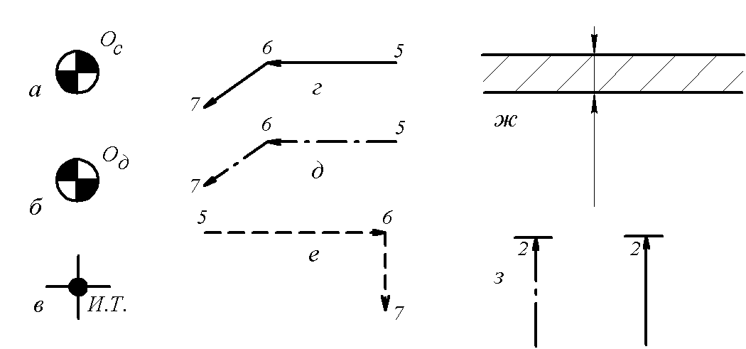
Rice. 2. Symbols on the map of sketches of elements of cyclograms:
a- machine zero, b- zero detail v- starting point G– movement of the tool at the working feed, d– movement of the tool at the working feed equidistant, e– moving the tool at rapid feed, well- allowance for processing, h- time delay
1.2. Contour equidistant and coordinate system
Parts processed on a CNC machine can be considered as geometric bodies consisting of simple geometric shapes, for example, a cylinder, a cone, a sphere, etc. During processing, the tool moves relative to the part (workpiece). The trajectory of the movement of the working body, i.e. the trajectory of a certain point of the tool, called the center, is set using the control program.
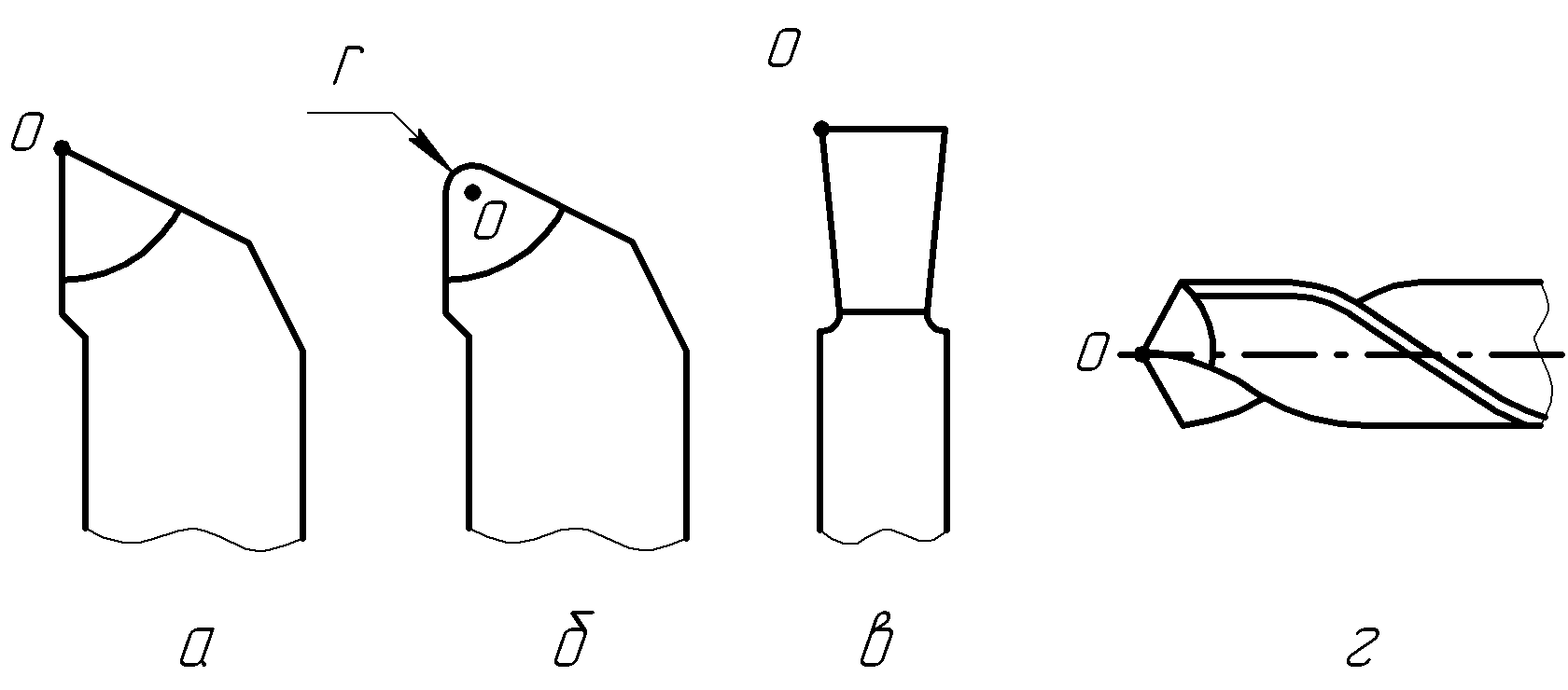
For through, boring and contour cutters, the center of the tool is the top of the cutter or the center of the radius at the top (Fig. 3, a, b) at the slotted (grooving) cutter - the left top (Fig. 3, v). For a drill, countersink, countersink, counterbore, die and tap, the center of the tool is the center of the working end (Fig. 3, G).
a B C D
Rice. 3. Tool Centers: a- a cutter with a sharp top; b- incisor
with a radius at the top; v- grooving and cutting cutter; G- drill
When contouring, the center of the tool must move along the equidistant contour of the part, i.e. according to the locus of points equidistant from any line and lying on one side of it. Equidistants are external E Nar and internal E vn (Fig. 4).
A special case of equidistant when turning with a cutter with a sharp tip is the contour of the part itself.
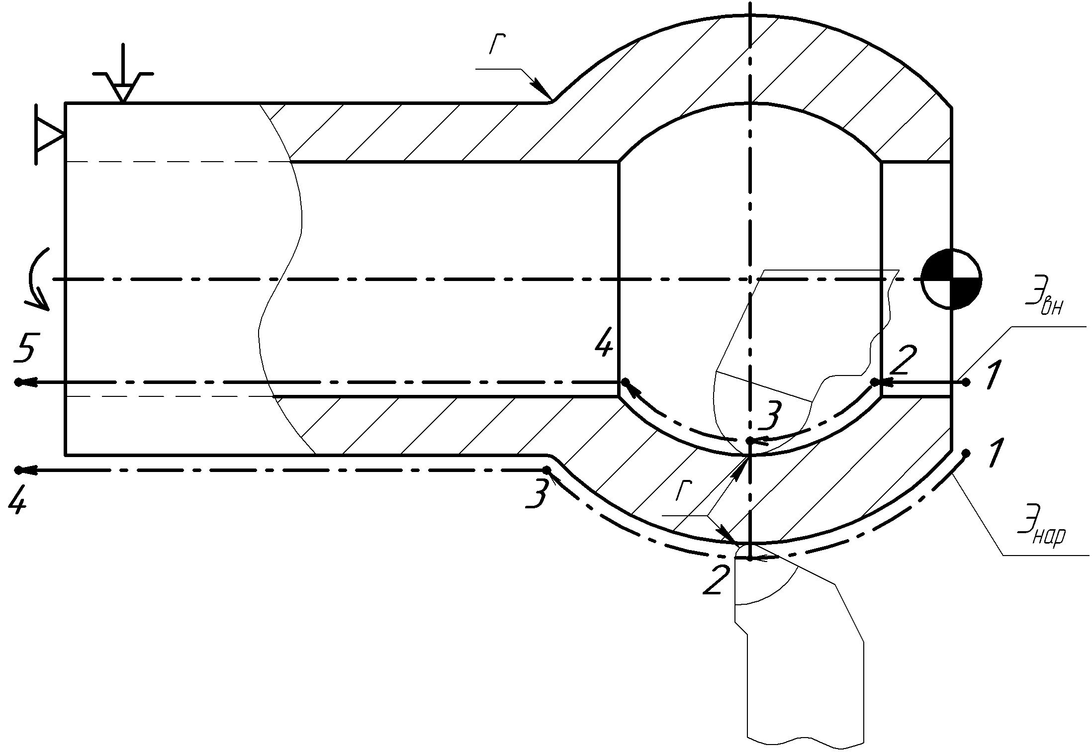
Rice. 4. Part Contour Equidistant
Separate sections of the trajectory of the tool center (cyclograms) can be segments of straight lines, arcs of circles or other curves. On fig. 5 shows the trajectories of the tool tip for roughing and finishing the shaft.
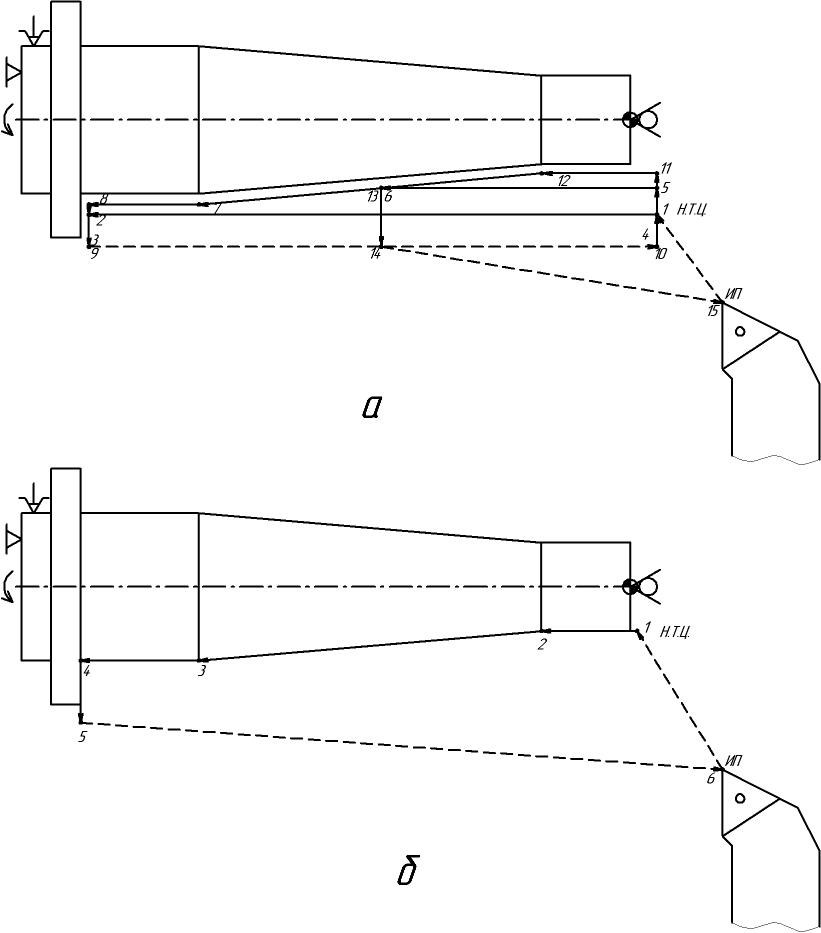
Rice. 5. Typical tool tip paths for turning
processing details: a- draft working passes; b– finishing working pass
The position of reference points (breaking points of the cyclogram) is determined using a coordinate system. For processing, a standard rectangular (Cartesian) coordinate system was adopted. In the coordinate system for lathes, the following axes are accepted: Z - parallel to the longitudinal feed of the caliper, coincides with the axis of the machine spindle, X - parallel to the transverse feed of the caliper.
For CNC lathes, a distinction is made between the machine coordinate system and the workpiece coordinate system.
Machine origin O With located in the center of the jaw chuck mirror, i.e. in the center of the spindle section in front of the landing cone centering the chuck faceplate (Fig. 6).
Rice. 6 . CNC lathe coordinate system: a- front
(or bottom); b- back (or top) location of the tool head
The direction of the coordinate axes depends on the location of the tool (for example, for machines 16K20T1 and 16A20F3 - in front of the spindle rotation axis, for machine 1713F3 - behind the axis of rotation). Movement along the X axis is realized by moving the cross slide of the caliper along the guides of the carriage, and along the Z axis - by moving the carriage along the guides of the bed. The origin of the workpiece coordinate system O d is located in the center of the left or right end of the workpiece. The Z axis of this system coincides with the Z axis of the machine, and the X axis runs in the plane of the base end of the fixture (for example, the end of the faceplate or the ledge of the cams) or in the plane of the right end of the workpiece. Dimensions relative to d, specified in the detail drawing, are converted into distances (coordinates) to the reference points of the processed contour (Fig. 7).
The coordinates of the reference points of the cutter tip cyclogram can be determined directly from the detail drawing or by calculations.
When setting up the machine, the so-called "binding" of the starting point is performed I.T., which coincides with the center of the tool, to the machine and workpiece coordinate systems. To avoid irrational idle runs, the amount of movement of the tool from the starting point of the program to the first surface to be machined should be chosen to be minimal.
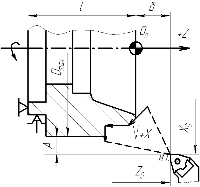
Rice. 7. Workpiece coordinate system
The position of the tool at the starting point should be clearly visible from the side of the worker. The tool should not interfere with the installation, fastening and removal of the part, removal of chips. For this distance from the point I.T. to the end of the workpiece b take within 60 - 80 mm, and to the outer surface of the workpiece A- 10 - 30 mm (Fig. 7). Point on the cyclogram, determined relative to the zero of the part O d, to which the tool center is approached according to the program from the starting point ( AND.T.), from which the direct cycle of working and auxiliary moves for processing the workpiece begins, is the starting point ( H.T.).
In the three-dimensional coordinate system familiar to us, there are three mutually perpendicular axes (X, Y, Z), which form the basis.
Most of the CNC machines in the initial-basic version only do 3-axis machining.
However, for some products of complex shape, this is not enough. Due to the additional modification - the installation of a rotary axis, CNC engraving and milling machines are capable of performing 4-axis processing.
Four-axis processing on an engraving-milling machine on a CNC machine using a rotary axis is in general a continuous processing of both symmetrical and non-symmetrical bodies.
Unlike conventional 3-axis machining of a 3D model, where the part must be attached on one side to the CNC machine table, 4-axis milling makes it possible to process the product from all sides continuously, without additional operations for rearranging the part on the desktop. This makes it possible to obtain products of complex shape. The manufacture of balusters, capitals, columns, pillars, legs of tables and chairs, chess pieces, as well as various figurines, rings of other jewelry and promotional souvenirs are the most common examples of such processing.
The variety of shapes, contours - any flight of fancy will be embodied in the processing of parts on an engraving and milling machine using the 4th rotary axis.
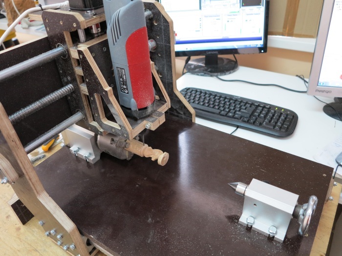
The main option for modifying, as mentioned earlier, a 3-axis machine to a 4-axis machine is the use of a rotary axis, figures 1 and 2.
Figure 1 shows a photograph of a rotary axis for a CNC machine, which allows for multi-sided processing.
Figure 1 Rotary axis for a CNC machine.
CNC milling modeler3040
Video of cutting a complex shape using a rotary axis using the example of a chess knight
Installation of a rotary axis on a 3-axis milling CNC cnc-3040al300
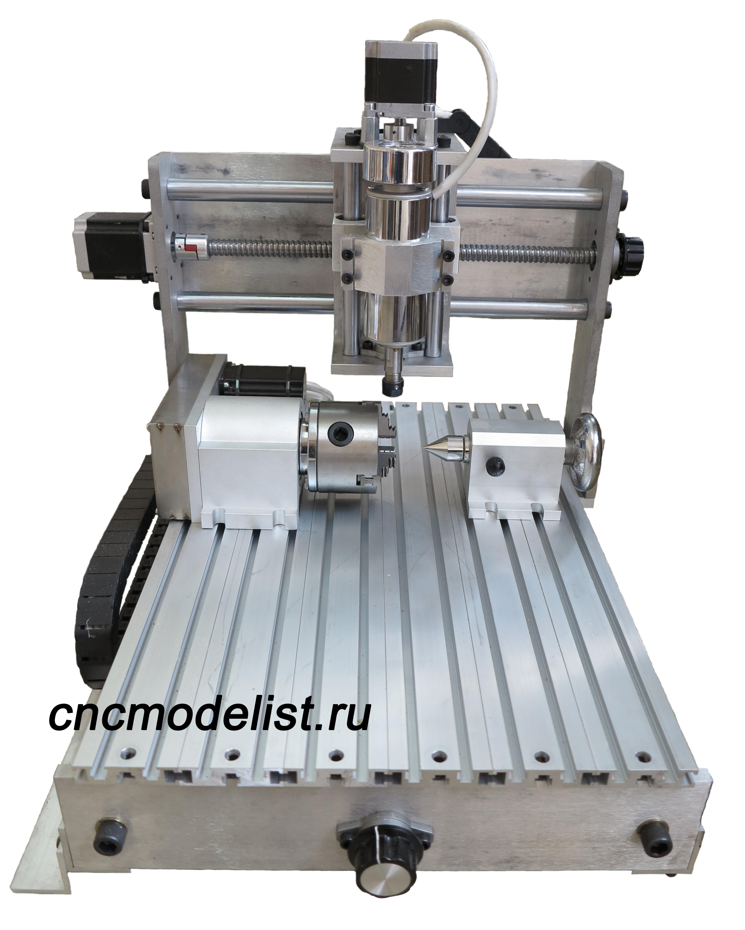
Figure 2 4-axis milling machine CNC
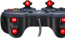
In addition, for continuous processing along 4 axes, the CNC system of the machine must still be able to control the repeated axis installed on it. Therefore, 4-axis machining implies not only the presence of a rotary axis, but also the use of an appropriate CNC system. The controller is most commonly used for this. stepper motors with 4 control channels or, more simply, a 4-axis controller. An example of a controller is shown in Figure 3. Channel A of this controller can be used to control a rotary axis installed on the machine.
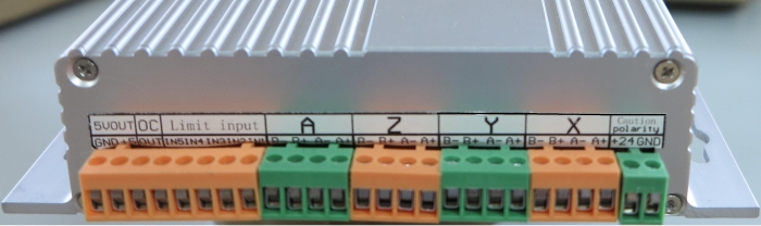
Figure 3
There are two types of 4-axis machining: the first is continuous and the second is positional machining (machining with indexing). Continuous processing - in this case, the cutter simultaneously moves through all degrees of freedom.
Positional processing - the rotary axis is used only to change the position of the workpiece, and the rest of the operations are performed in three-dimensional processing mode.
To work with a rotary axis, it is necessary to configure the control program. Below are the settings for Mach3 for 6:1 and 4:1 rotary axes. Figure 4 shows the pin settings of the LPT port for the aluminum cased stepper motor controller shown in Figure 3.
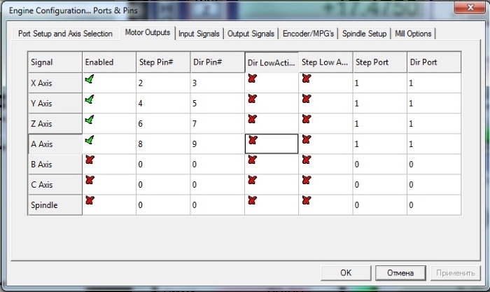
Figure 4
Figure 5 - settings for a rotary axle with a ratio of 4:1.
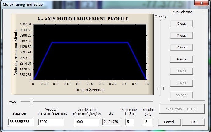
Figure 5
Figure 6 - settings for a rotary axle with a ratio of 6:1.
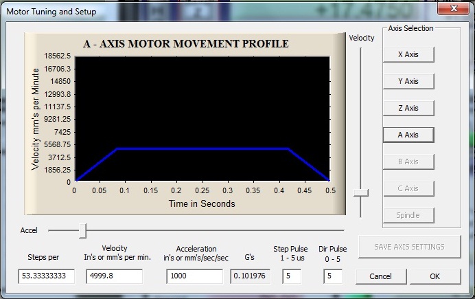
Figure 6
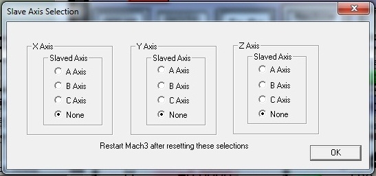
Figure 7
Control programs for working with multi-sided processing are available in DeskProto, PowerMill, etc.
Figure 8 shows the result of multi-sided machining on a 4-axis milling cnc CNC-3040AL2
Figure 8. Multi-sided machining on a 4-axis desktop CNC using a rotary axis
UDC 621.9.06-529:006.354 Group G8|
STATE STANDARD OF THE UNION OF THE SSR
METAL-CUTTING MACHINES WITH NUMERICAL PROGRAM CONTROL DESIGNATION OF COORDINATE AXES AND DIRECTIONS OF MOVEMENT
(ST SEV 3135-81)
General provisions
Machine tools, numerically controlled Designation of axis and motion directions.
General statements
Introduction date 01.07 80
This International Standard applies to machine tools with numerical program management(CNC) and establishes the designation of the coordinate axes and directions of movement of the working bodies of the machine associated with the workpiece being processed (hereinafter referred to as the workpiece) and the tool.
The standard can be used for other types of CNC equipment
The standard fully complies with ST SEV 3135-81.
The standard is fully compliant international standard ISO 841-74.
(Changed edition, Rev. No. 1, 2).
I. DESIGNATION OF THE DIRECTIONS OF MOVEMENTS IN MACHINES IN THE STANDARD COORDINATE SYSTEM
1.1. The standard establishes the designation of the coordinate axes and the direction of movement in the machines as follows. so that the programming of machining operations does not depend on whether the tool or the workpiece is moved.
The basis is the movement of the tool relative to the coordinate system of the stationary workpiece.
1.2. The standard coordinate system is a right-handed rectangular coordinate system (see drawing) associated
with a workpiece whose axes are parallel to the straight guides of the machine.
1.3. The positive direction of movement of the working body of the machine preferably corresponds to the direction of retraction of the tool from the workpiece.
1.4. When using a machine for drilling or boring, using only three basic linear movements.
processing will occur when the tool is moved in the negative direction of the Z axis.
1.5. On the schematic drawings of machine tools, the directions of movement of the working bodies carrying the tool should be indicated by letters without a stroke, and those carrying the workpiece - by letters with a dash; while the positive direction of movement, denoted by a letter with a stroke, is opposite to the corresponding movement, denoted by the same letter without a stroke.
2. Z-AXIS MOVEMENT
2.1. The Z axis (with the exception of the case specified in clause 2.5.) is determined in relation to the main movement spindle, that is, the spindle rotating the tool in the machines of the drilling-milling-boring group or the spindle rotating the workpiece in the lathes of the turning group.
2.2. If there are several spindles, one of them should be chosen as the main one, preferably perpendicular to the working surface of the table on which the workpiece is mounted.
2.3. When the axis of the main spindle is fixed, one of the three axes of the standard three-coordinate system, parallel to the spindle axis, should be taken as the Z axis.
2.4. In cases where the axis of the main spindle can be rotated, you should:
if it can only be in one position * parallel to one of the axes of the standard three-coordinate system - this standard axis is taken as the axis 7.\
if it can be in several positions, parallel * to various axes of the standard three-coordinate system, the Z-axis is taken to be the standard axis, preferably perpendicular to the working surface of the table on which the workpiece is mounted.
2.5. In the absence of a spindle in the machine, the axis 7. should preferably be perpendicular to the working surface of the table.
2.6. Movement along the Z-axis in the positive direction must correspond to the direction of retraction of the tool from the workpiece.
3. MOVEMENT ON THE X-AXIS
3.1. The X-axis should preferably be positioned horizontally and parallel to the workpiece mounting surface.
3.2. On machines with a non-rotating tool and workpiece, such as planers, the X-axis must be positive in the direction of the main movement and parallel to it.
3.3. On machines with a rotating workpiece, such as lathes, the X-axis movement is directed along the radius of the workpiece and parallel to the transverse guides. Positive X-axis movement occurs when the tool mounted on the main tool holder of the cross slide moves away from the axis of rotation of the workpiece.
3.4. On machines with rotating tools, e.g. milling, drilling:
with a horizontal Z axis, the positive movement of X is directed to the right, when viewed from the main tool spindle to the product;
with a vertical axis of 1, the positive movement in the X-axis is directed to the right for single-column machines, when viewed from the main tool spindle to the column, and for two-column machines, when viewed from the main tool spindle to the left column.
4. Y-AXIS MOVEMENT
5.1. The positive direction of movement along the Y-axis should be chosen as follows. so that the Y-axis, together with the Z and X axes, forms a right-handed rectangular coordinate system (see drawing).
5. ROTATIONAL MOVEMENTS A. B and C
5.1. The letters A, B and C should denote rotational movements around the axes parallel to X, Y and Z, respectively.
5.2. The positive directions A, B and C must match the direction of screwing the screws with right-hand thread in the positive directions of the X, Y and Z axes respectively (see drawing).
6. ORIGIN OF THE STANDARD COORDINATE SYSTEM
6.1. The location of the origin of the standard coordinate system, (X=0, Y-O, Z-0) should be chosen arbitrarily.
6.2. The origin of movements A, B and C should be chosen arbitrarily.
7. ADDITIONAL AXES
7.1. Rectilinear motion
7.1.1. If, in addition to the main (primary) rectilinear movements X, Y and Z, there are secondary movements parallel to them, they should be designated U, V and W, respectively.
If there are additional tertiary movements parallel to them, they should be designated P. Q and R, respectively.
If there are additional straight-line movements that are not or may not be parallel to X, Y or Z, they should be designated as U, V, W, P, Q or R.
Note. For a horizontal boring machine, the movement of the half-bolt of the radial support should be denoted by the letters U or P, if these letters are not occupied with the indicated movement of the table X, since in this case the movement of the cutter, although close to the spindle, is oblique.
7.1.2. Primary, secondary and tertiary movements of the working bodies of the machine are determined preferably in accordance with the distance of these bodies from the main spindle.
Notes:
a) For a radially welded stack, the movement of the spindle sleeve and tra-aers should be indicated respectively by the letters 7. and \T
b) For a lathe, up to the pc-sled to the turret sled, located farther from the spindle, should be denoted by the letters Z and 1Г, respectively.
c) For machines with two functionally identical working bodies controlled from two independent two-coordinate CNC devices (mayrimer, for lathes with functionally identical two spindles and calipers), o: and coordinates for both equally working bodies (for example, calipers) should be designated the same - letters 7. and X.
7.2. rotational movement
If, in addition to the primary rotational movements, there are secondary rotational movements, parallel or non-parallel A, B and C, they should be designated O and E.
7.3. Examples of designations of the main and additional coordinate axes and positive directions of movement in CNC machine tools are given in the reference appendix to this standard.
APPENDIX
Reference
DESIGNATION OF COORDINATE AXES AND POSITIVE DIRECTIONS OF MOVEMENT IN METAL CUTTING CNC MACHINES


")
 Download new houses for GTA San Andreas")


Chief Power Engineer: duties and job description
How to Write and File an Overpayment Credit Claim Download the Credit Claim Form
Features of investigating a work injury on the way to work, home, and also during a lunch break Work injury during a lunch break
Reservation service (role, functions, characteristics) Requirements for a reservation manager
Products for pregnant women The best products for pregnant women