Self-exciting chucks chucks have two or three knurled eccentric cams, with which they capture the workpiece at the start of cutting and cause it to rotate; As the cutting torque increases, the chuck torque automatically increases as well. Therefore, they work reliably with any chip cross-sections. Parts, as usual, are installed on fixed or floating centers. For ease of installation of parts on centers, structures with automatically opening cams are used, and to ensure uniform clamping by all cams, a floating cam system or a system with cams of independent action is used.
Rice. 11.1- Driver chuck.
Cam-driven chucks are widely used on multi-cutting lathes where high torque transmission is required.
When operating conventional eccentric chucks, there are cases when the workpiece is rotated under the action of cutting forces at the beginning of processing, which leads to breakage of the cutter. To eliminate this shortcoming and increase the automaticity and reliability of the action, lead chucks with loads based on the use of centrifugal inertia forces have recently been introduced. The introduction of these cartridges is facilitated by the speed of the spindles of modern lathes.
On fig. 11.1 shows a chuck with eccentric jaws. The chuck flange is bolted to the adapter flange or directly to the spindle flange as shown. The chuck body is connected to the flange 14 by means of screws with spacers and leading pins. The housing can move relative to the flange in the direction of its grooves, which ensures uniform clamping of the workpiece by cams 2; springs 11 return the body to its original central position.
Eccentric cams 2 are freely mounted on the fingers and have a notch on the profile. With the beginning of the rotation of the spindle, the cams, under the action of the centrifugal force developed by the weights 1, clamp the workpiece and cause it to rotate; further clamping is carried out during the cutting process. When the machine is stopped, the cams under the action of the springs 11 are automatically opened by the pushers 20. By changing the cams, the chuck can be used to clamp parts with diameters from 30 to 150 mm.
The fixing of the workpieces occurs due to centrifugal force.
![]()
Centrifugal driving chucks, depending on their diameter, can hold loads with a total weight of -3 to 6 kg. Then, for example, at G = 3 kg, R = 45 lsh, n = 500, 1000, 2000 rpm, the centrifugal force pressing the cams to the workpiece will be Pc = 34, 138, 552 kg/s, respectively.
The accuracy of the technological operation is characterized by the value of the installation error and depends on the magnitude of the errors of basing b, fixing h and the position of the workpiece in the fixture etc. In the general case, the installation error
Workpiece position error in fixture
where p - error arising from errors in the manufacture of fixtures, p = 15 µm; s - error that occurs when the device is installed on the machine, s = 10 microns; and - the error arising from the wear of the installation parts, the amount of wear is approximately determined by the empirical dependence:
where N is the number of contacts of blanks with supports in 1 year, N = 50000; a and - empirical coefficient and exponent = 0.7, = 0.5:
The value of And is of great importance, therefore, we divide And by four, and in technical requirements we write to the equipment: change the supports after two months of operation (6 times a year). Thus, we accept and \u003d 26 microns.
pr === 31.63 µm.
The error of basing and fixing the workpiece is 0, therefore, the installation error is equal to the fixture error
Unlike conventional leash devices with a finger and a collar (GOST 2571-53 and GOST 2572-53) self-gripping chucks chucks have two or three knurled eccentric cams, with which they capture the workpiece at the start of cutting and cause it to rotate; As the cutting torque increases, the chuck torque automatically increases as well. Therefore, they work reliably with any chip cross-sections. Parts, as usual, are installed on fixed or floating centers. For ease of installation of parts on centers, structures with automatically opening cams are used, and to ensure uniform clamping by all cams, a floating cam system or a system with cams of independent action is used.
Cam chucks are widely used on multi-cutting lathes where high torque transmission is required.
When operating conventional eccentric chucks, there are cases when the workpiece is rotated under the action of cutting forces at the beginning of processing, which leads to breakage of the cutter. To eliminate this shortcoming and increase the automaticity and reliability of the action, lead chucks with loads based on the use of centrifugal inertia forces have recently been introduced. The introduction of these cartridges is facilitated by the speed of the spindles of modern lathes.
In FIG. 22 shows a chuck with eccentric cams designed by the Moscow Machine-Tool Plant. Ordzhonikidze. The flange 1 of the chuck is bolted to the adapter flange or directly to the spindle flange as shown in the figure. The body 3 of the chuck is connected to the flange 1 by means of screws 5 with spacers 6 and leading pins 2. The body 3 can move relative to the flange 1 in the direction of its grooves, which ensures uniform clamping of the workpiece by the cams 4; springs 9 return the body to its original central position.
The eccentric cams 4 are freely mounted on the fingers 2 and have a notch on the profile. With the beginning of the spindle rotation, the cams, under the action of the centrifugal force developed by the weights 10, clamp the workpiece and cause it to rotate; further clamping is carried out during the cutting process. When the machine is stopped, the cams under the action of springs 5 are automatically opened by pushers 7; to unload the fingers 2, they are pressed with their semi-cylindrical surface to the radius recesses in the body 3. By changing the jaws, the chuck can be used to clamp parts with diameters from 30 to 150 mm.
The magnitude of the centrifugal force is directly proportional to the square of the speed n rpm of rotation of the machine spindle and is determined by the formula
![]()
where Rn - centrifugal force in kgf;
u - weight of rotating weights in kg;
R - distance from the center of gravity of the load to the axis of the machine spindle in m;
g is the free fall acceleration in m/sec2; g = 9.81 m/s2.
Centrifugal driving chucks, depending on their diameter, can hold loads with a total weight of -3 to 6 kg. Then, for example, at G = 3 kg, R = 45 lsh, n = 500, 1000, 2000 rpm, the centrifugal force pressing the cams to the workpiece, respectively, will be Pc = 34, 138, 552 kgf.
Two-jaw chucks are normalized (MN 4051-62) and have a normalized floating (drowning) spring-loaded center (MN 4052-62).
In FIG. 23 shows the designs of a normalized two-jaw chuck and its floating center.
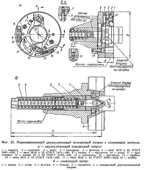
The main dimensions of cartridges and centers are given in table. 3.
For clamping parts with a diameter of 17 to 72 mm, seven sets of interchangeable eccentric jaws are provided with a normal, and for diameters from 28 to 112 mm - 8 sets of interchangeable cams; the parameters of the eccentric cams and the floating center (part 1) are normalized. The material of the cams is steel grade SHKH15 GOST 801-60; hardness - HRC 60-64. Center material - U8A steel according to GOST 1435-54; cone hardness 60° HRC 55-60, the rest - HRC 45-50.
|
Table 3 Two-jaw chucks and recessed centers (dimensions in mm)
|
||||||||||||||||||||||||||||||||||||||||
At the factory "Frazer" them. M. I. Kalinina designed and put into production a three-jaw centrifugal chuck.
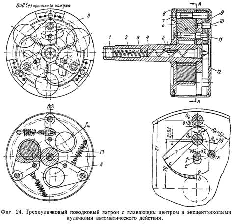
The cartridge (Fig. 24) is a welded body "3, in which there is a floating center 4 with a spring 2 and three weights or a balancer 6U
mounted on 7 axles; the balancers are connected to the clamping jaws 9 by fingers 11. The cams are mounted on axles 10 pressed into the front wall of the cartridge.
The axial movement of the center 4 is limited by the screw 5. The center has a conical neck and in the working position is mated with the conical socket of the cartridge body, which eliminates its beating. The force of spring 2 is adjusted by screw 1.
To increase the weight of the balancers 6, they are provided with holes with a diameter of 50 mm, filled with lead; The weight of each balancer is approximately 2 kg. The balancers are under the action of springs 13, holding them in a non-working position. The cartridge is closed by a casing 8 and a cover 12 fixed on its body with screws.
When working on the cams 9, in addition to the cutting forces, there are also centrifugal forces from the balancers transmitted by the fingers 11. As a result, the cams are tightly pressed against the workpiece and do not allow it to rotate relative to the chuck.
In the chuck design, the distance from the center of gravity of each load to the spindle axis is R = 0.05 mm. Then at G = 2 kg; n \u003d 1000 rpm, the centrifugal force acting on each cam, according to the previous formula, will be
The total force Rts. sum = 102-3 = 306 kgf.
The presence of such a force eliminates the possibility of turning the workpiece at the beginning of cutting.
After processing the part and stopping the spindle, the balancers 6 return to their original position under the action of the springs 13 and, entraining the cams 9, automatically open them, freeing the workpiece.
The chuck provides a uniform clamping of the workpiece without the use of a floating system of cams, since in the case of an eccentricity of the workpiece, centrifugal forces clamp it at different points on the ca curve.
Three-jaw chucks of a similar design and eccentric cams are normalized to them (MN 4050-62). The diameter of the clamped parts is from 12 to 85 mm.
Driver chucks and collars
| Parameter name | Meaning |
| Article subject: | Driver chucks and collars |
| Rubric (thematic category) | Metals and Welding |
Centers
Tools and fixtures for turning
Cutting conditions for metal turning
The elements of the cutting mode when turning a workpiece are cutting speed, feed and depth of cut. Cutting speed is usually called the length of the path traveled by the cutting edge of the tool relative to the machined surface of the workpiece per unit time. Cutting speed is measured in m/min and is indicated by the letter υ.
It is customary to call the feed the amount of movement of the cutting edge of the tool in one revolution of the workpiece (in the feed direction) or per unit of time. The feed is measured in mm/rev or mm/min, denoted by the letter s and must be longitudinal (if the tool moves parallel to the axis of rotation of the workpiece) and transverse (if the tool moves perpendicular to this axis). The depth of cut is usually called the value of the metal layer cut off in one pass of the cutter, measured along the perpendicular to the machined surface of the part. The depth of cut is measured in millimeters and is indicated by the letter t.
The workpiece has the following surfaces:
machined (from which chips are removed), machined (obtained after chip removal) and cutting (which is transitional between machined and machined surfaces and is formed by a cutting tool).
Lecture 3 (2 hours)
2. Driver chucks and collars
3. Collet chucks. Diaphragm cartridges
4. Fixing workpieces
centers. Given the dependence on the shape and size of the workpieces, centers of various types are used. The angle at the top of the working part of the center is usually 60 °. The conical surfaces of the working and tail parts of the center should not have nicks, as this leads to errors in the processing of workpieces. Bore diameter is smaller than the small diameter of the tail cone, which allows the center to be knocked out of the socket without damage conical surface tail section.
The center serves to install workpieces with a diameter of up to 4 mm. For these blanks, instead of center holes, an outer cone is made with an angle at the top of 60 °, which enters the inner cone of the center; in connection with this, such a center is usually called a reverse center. If it is extremely important to cut the end of the workpiece, then the rear cut center is used, which is installed only in the rear quill grandmas.
A center with a spherical working part is used in cases where it is required to process a workpiece whose axis does not coincide with the axis of rotation of the machine spindle.
The center with a corrugated surface of the working part is used when processing workpieces with a large center hole without a driver chuck.
During processing, the front center rotates with the part and serves only as a support, while the back center does not rotate and, therefore (due to loss of hardness from increased heating), it wears out intensively. To prevent wear, the working part of the rear center is made of hard alloy. When processing with high cutting speeds and loads, rear rotating centers are used. In the tail section of the center, an axle is mounted on rolling bearings, at the end of which a working part center, which ensures its rotation along with the workpiece being processed.
When processing in the centers, the movement of the workpiece can be transmitted by a driving chuck through a driving pin and a collar , which is attached to the part with a screw.
It is important to note that in order to reduce auxiliary time during roughing in the centers of shafts with a diameter of 15-90 mm, self-tightening driving chucks are used. The workpiece is installed in the centers of the machine and pressed with the tailstock quill. At the same time, the center of the chuck, moving, compresses the springs until the workpiece with its end presses the collet ,
which firmly fixes the center.
Hosted on ref.rf
When starting the spindle, together with the chuck body, the ring is rotated, the ĸᴏᴛᴏᴩᴏᴇ is attached to the body with screws. The ring with its fingers rotates the cams counterclockwise relative to the axes until the toothed surface of the cams touches the surface of the workpiece. The clamping force of the workpiece with the cams depends on the cutting force. For uniform load on the jaws, the ring ,
in which the pins of the axis are fixed, can move in the radial direction and provide self-alignment of the cams on the surface of the workpiece. After the spindle stops, the part, rotating by inertia, turns the cam disc clockwise relative to the axes and is released from the mount.
The transmission of rotation from the spindle to the workpiece to be processed, installed in the centers of the machine, is carried out using a clamp, which is put on the workpiece and fixed with a screw, while the collar shank rests against the pin of the driving chuck.
More convenient to use is a self-tightening clamp, in which the shank is fixed in the body movably on the axis . The lower part of the shank, facing the workpiece, is made eccentrically with respect to the axis and has a notch. To install the clamp on the workpiece, the shank is tilted towards the spring , which, after installing the clamp, preliminarily tightens the workpiece with a shank. In the process of processing, the chuck pin leads the final tightening of the workpiece with the shank in proportion to the cutting force.
Driving cartridges and clamps - the concept and types. Classification and features of the category "Drive chucks and clamps" 2014, 2015.
Processing in centers. Many parts on lathes are processed in centers. The simplicity and uniformity of the installation method for a large range of parts, as well as the high accuracy of the installation of workpieces both at the preliminary and final stages of processing, contribute to its wide application. To transfer the torque to the workpiece, a clamp is used, driven by the finger of the driving chuck. After processing all the steps of the right end of the workpiece, it is reset and processed from the other end.
This scheme has three main disadvantages:
1) the need to secure a leash at the left end of the workpiece, which requires high costs manual labor skilled worker;
2) for the complete processing of the shaft, the workpiece must be reinstalled, which also requires manual labor;
3) basing due to the centering depth error on a rigid center leads to large errors in the position of the workpiece along the length, which makes it difficult to set up the machine for automated production linear dimensions shaft.
Driver chucks

The first drawback is eliminated by the use of designs of driving cartridges that do not require the use of a collar. In these chucks, the workpiece rests on the center, and the cam clamp is used only to transmit torque, so they are made floating, i.e. if one of the cams rests on the surface of the workpiece and its movement stops, while the other cams continue to move until the workpiece is clamped by all cams with the same force.
To fasten the mandrel, the force transmitted from the tailstock quill to the front center is used, which moves to the left and pulls a ring with three lever cams attached to the axes. The rear ends of the jaws, resting on a conical ring, move apart, and the front ends fix the cylindrical part of the mandrel or workpiece.
The supporting conical ring is installed with sufficient radial clearance and is supported in the middle position by springs. Therefore, if one of the cams rests against the surface of the workpiece, then with further movement of the ring, the rear end of the cam presses on the support ring and displaces it in the radial direction, accelerating the movement of the cams from the opposite side.
In a self-tightening driver chuck, cutting forces are used to hold the workpiece. The workpiece in the radial direction is based on a spring-loaded center. When pressing the workpiece rear center it moves to the left, compressing the spring until the end rests against the collet, which clamps the front center.
To transmit torque, cams with a curved corrugated working surface are used. When the spindle is turned on, the ring starts to rotate. Since the ring with the axes of the cams is still in place, the cams rotate on the axes until the working surface comes into contact with the surface of the workpiece. The ring is made floating to equalize the clamping forces with all cams when the workpiece surface is beating.
At the beginning of processing, under the action of cutting forces tending to stop the workpiece, the cams additionally rotate around the axes in the direction of the arrow and, with a corrugated surface, are even more strongly pressed against the workpiece, wedging it. Detachment of the shaft after processing occurs by turning it by inertia in the direction of rotation when the spindle is braked.
In this design of the driving chuck, in addition to reducing the time for installing and removing the workpiece, the accuracy of its basing in the axial direction is increased, since the left base end of all workpieces processed in the chuck occupies the same position regardless of the depth of the center hole.
Pin and toothed driver chucks
Shaft processing is promising using pin or toothed driver chucks, which transmit torque through the end, leaving free for processing outer surface shaft. In this case, all shaft stages, including the one closest to the headstock, can be machined from one setup. The workpiece is installed in the front floating center and rear rotating. It is pressed against the pins of the cartridge by a tailstock quill with a hydraulic cylinder. The hydraulic cylinder creates and during processing maintains the necessary clamping force of the workpiece to the chuck pins.
Due to the ability to self-align, the pins are pressed against the end of the workpiece with the same force and participate in the transmission of torque, despite possible deviations from the perpendicularity of the end of the workpiece to the axis of the centers. Such chucks, having a spring-loaded front center, well base the workpiece in the axial direction. These advantages of pin and toothed chucks make it possible to effectively machine shafts not only on universal equipment, but especially on automated machines, including CNC and GPS machines.


How to understand: will the kitten be fluffy?
What kind of light alcohol can be drunk for pregnant women: the consequences of drinking
Why do the legs swell in the ankles and ankles of the feet in pregnant women: causes and methods of treatment
The wedding of Prince Harry and Meghan Markle: scandalous and secret details of the marriage (photo) The future marriage of Prince Harry year NTV
How to close white plums for the winter