SURFACE ROUGHNESS
PARAMETERS, CHARACTERISTICS AND SYMBOLS
GOST 2789-73
(ST SEV 638-77)
USSR STATE COMMITTEE FOR PRODUCT QUALITY MANAGEMENT AND STANDARDS
STATE STANDARD OF THE UNION OF SSR
|
SURFACE ROUGHNESS Parameters and characteristics The structure of the resulting surface During honing, stones are pressed against the surface mechanically, hydraulically or pneumatically. The kinematics of the working movements lead to angular intersections on the machined surface. Within the length of the hole to be machined, the head must perform work jumps in order to minimize the occurrence of a situation where the grain would fall into the path previously traveled. These mutually crossed recesses are called geometric flat plate. The resulting cracks with different depths can act as lubrication channels. Such a structure on the machined surface significantly reduces the time to reach the interacting surfaces, and surface wear is also reduced. surface roughness. Parameters and |
GOST (CTSEV 638-77) Instead |
from 01.01.75
1. This standard applies to the surface roughness of products, regardless of their material and method of manufacture (obtaining the surface). The standard establishes a list of parameters and types of irregularity directions that should be used when setting requirements and controlling surface roughness, numerical values of parameters and general guidelines for setting requirements for surface roughness. The standard does not apply to the roughness of fleecy and other surfaces, the characteristics of which make it impossible to standardize and control roughness by the available methods, as well as to surface defects resulting from material defects (sinks, pores, cracks) or accidental damage (scratches, dents, etc.). ). The standard fully complies with CT SEV 638-77 and the international standardization recommendation ISO R 468. 2. Requirements for surface roughness should be established based on the functional purpose of the surface to ensure the specified quality of products. If this is not necessary, no surface roughness requirements are specified and the surface roughness need not be controlled. 3. Requirements for surface roughness should be set by specifying the roughness parameter (one or more) from the list given in clause 6, the values of the selected parameters (according to clause 8) and the basic lengths at which the parameters are determined. If the parameters Ra, Rz, Rmax are determined on the base length in accordance with Table. 5 and 6 of Reference Appendix 1, these basic lengths are not specified in the roughness requirements. If necessary, in addition to the surface roughness parameters, requirements are set for the direction of surface irregularities, for the method or sequence of methods for obtaining (processing) the surface. Numbers from the table. 2-4 and p. 9 are used to indicate the largest and smallest allowable values, the limits of the allowable range of values and the nominal values of the roughness parameters. For the nominal numerical values of the roughness parameters, permissible limit deviations should be established. Permissible limit deviations of the average values of the roughness parameters as a percentage of the nominal values should be selected from a range of 10; twenty; 40. Deviations can be unilateral and symmetrical. 4. Requirements for surface roughness do not include requirements for surface defects, so when controlling surface roughness, the influence of surface defects should be excluded. If necessary, requirements for surface defects should be specified separately. 5. It is allowed to establish requirements for the roughness of individual surface areas (for example, surface areas enclosed between the pores of a large-porous material, for sections of the cut surface that have significantly different irregularities). The requirements for surface roughness of individual sections of the same surface may be different. 6. Roughness parameters (one or more) are selected from the given nomenclature: Ra - arithmetic mean deviation of the profile; Rz - the height of the profile irregularities at ten points; P max - the highest profile height; Sm - average step of irregularities; S is the average step of the local protrusions of the profile; tp is the relative reference length of the profile, where p are the values of the level of the profile section. The Ra parameter is preferred. 1-6. 7. Types of directions of surface irregularities are selected from Table. one.
With regard to internal combustion engines, the wear resistance of cylinder liners significantly affects the life of the engine. Increasing the wear resistance of the liner reduces the life of the engine. This is achieved machining mating surfaces and friction. Although functions are irregular, their placement should be regular. In the case of smoothing, the profile of the applied stone is determined and the force of the tool applied to the working surface is determined.
The flat plate structure described above is not the only one that can be obtained by smoothing. One-sided smoothing allows you to track parallels with the axis of the workpiece. The parallel structure of the direction of movement of the piston is characterized by a favorable reduction in frictional forces during the interaction of a pair of piston cylinders. This arrangement does not remain neutral to lubrication conditions. Achieving a slower level of consumption of interacting components is the economic rationale for using such a solution.
Table 1
|
Types of roughness directions |
Schematic representation |
Explanation |
|
Parallel |
Parallel to the line depicting the surface in the drawing, the requirements for the roughness of which are established | |
|
Perpendicular Abrasive brushes The brushes adapt - thanks to the flexibility of their design - to the surface to be treated. As with honing stones or simple sandpaper, different abrasive gradations are different. Brushes are used for finishing surfaces and cylindrical holes, blanking plugs and finishing non-cylindrical holes, as well as uniform, finely ground surfaces with the ability to hold a thin film of oil. For valve blocks, a honing operation is used with brushes before boring with a diamond knife tool. |
Perpendicular to the line depicting the surface in the drawing, to the roughness of which requirements are established | |
|
criss-cross |
Crossing in two directions oblique to the line depicting the surface in the drawing, the roughness of which is specified | |
|
Arbitrary |
Different directions in relation to the lime, depicting the surface in the drawing, the roughness of which is set requirements | |
|
circular This allows you to increase the service life of the diamond tool. The advantage of these brushes is that they do not have stones that are crushed. They are used to obtain the desired microgeometry and metallurgical structure of the surface layer. In their case, there is no need to spend time installing the tool. This flexibility in application is an advantage of this type of design. Figure 3: Method for honing a hole using a horn with a whip. Figure 4: Effect of machining on honing brushes at the edge of a hole. As with whisker honing, a plateau surface is also obtained with honing brushes. Machining with these brushes is a sanding process with little tool pressure on the work surface without the need to raise the temperature in the work area. The honing process with a brush allows you to get the structure of the metal base without surface impurities. |
Approximately circular in relation to the center of the surface, the roughness of which is specified | |
|
Radial |
Approximately radial to the center of the surface whose roughness is being specified |
table 2
The elasticity of honing brushes allows the tool to adapt to the shape of the workpiece, so there is no need for cylindrical machining. Shenanigans are prone not only to surfaces, but also to edges, which, due to the usefulness and rheological aspects of fluid flow, as well as non-Newtons, have a beneficial effect.
Processing time should be between 5 and 60 seconds. Grinding with honing brushes also requires lubrication. Full oils with a viscosity of 10 to 30 or an emulsion refrigerant are recommended. It is allowed to use grease in the sprayer, and in the case of brake cylinders, hydraulic oil for the brakes. It is not recommended to use diesel, oil and fat soluble solvents due to reduced brush life.
|
100 |
0,100 |
|||
|
0,80 |
||||
|
6,3 |
||||
|
50 High Precision Honing - whether with bleach or brushes - is a kind of abrasive treatment. Honing with brushes cannot replace honing using an honor and honor head. Hong brushes and their capabilities complement and expand the applicability of this type of treatment. Drilling heads allow processing a large thickness of the cut. Brushed finish is a micron or hundredth of a millimeter. Surface requirements do not always provide honing special machines and white heads. Surface machining requires specific tool kinematics, which is obtained by machining with both tools. Honing allows to achieve high dimensional accuracy and the shape of the machined surface, while obtaining the special properties of the top layer. The surface treated compared to sanding is less damaged and has a higher smoothness. The resulting directional structure is more favorable for the mechanical interaction of elements. The processing speed is less, and the pressure of the tool on the working surface is less than in grinding. |
0,050 |
|||
|
0,40 |
||||
|
3,2 |
||||
|
25 |
0,025 An important benefit of honoring is the ability to correct hole shape errors and surface geometry. In conclusion, honing is characterized by: high efficiency. Simple operation, short preparation time. Independence from the accuracy and quality of workmanship obtained with the accuracy of the workpiece and workpiece. small thermal distortion. This makes this processing method a very interesting manufacturing technique that has a certain scope as a finish. Precision surface treatment is a technology area that is generally considered a side effect. This is a very inappropriate approach. It is well known that, from a qualitative point of view, treatment is divided into the following stages. |
|||
|
0,20 |
||||
|
1,60 |
||||
|
12,5 |
0,012 |
Table 3
Roughing, molding, finishing. . The separation, including honing, especially in the most precise, ultra-precise range from geometric accuracy and surface roughness, is usually marginal. Technological reality, requirements for critical building surfaces make the use of microsampling technology necessary, mainly due to the lack of other technological possibilities.
The definition of a micro-sample is due to its technical implementation. Dimensional form accuracy requirements, surface roughness, overall workpiece size and the need to use miniature tools. In the processing process, which is called micromachining, it is due to the qualitative nature of the geometric dimensions, shape errors and surface roughness. Honing processes various objects and surfaces. In a strict sense, reverence is not considered a micro-scale.
|
100 |
0,100 |
||||
|
0,80 |
|||||
|
6,3 Abrasive abrasives are attached to the head body, which is pressed against a surface that can be machined or hard-worked. In classical worship, the head performs reciprocating movements. The movement of the hinge can be performed by the head or the workpiece. Honing Plateau - Aims to obtain the geometric structure of a plateau called a plateau. It is characterized by regular functions that can act as lubrication pipes. The features are deep and small. This surface makes the time required to reach the mating surfaces significantly reduced and surface wear is reduced. It is assumed that the surface has a cross-cut texture, and the resulting recesses improve lubrication conditions. |
|||||
|
50 |
0,050 |
||||
|
400 |
0,40 |
||||
|
3,2 In the case of internal combustion engines, the resistance of worn cylinder liners affects the life of the engine. Increased resistance is achieved by mechanical processing of working surfaces and the influence of friction forces. As long as functions are irregular, their placement should be regular. Machining with these brushes is a sanding process with little tool pressure on the work surface without the need to raise the temperature in the work area. Processing depends not only on surfaces, but also on edges, which, due to the usability and rheological aspects of fluid flow, as well as non-Newtonian, have a beneficial effect. Honing increases the wear resistance of the surface and thus increases the durability of the mechanisms. Providing the best surface properties for hydraulic cylinders, pneumatic cylinders with cross holes and air ducts, surface treatment for roll joints, plateau surfaces for internal combustion engines, regeneration, cleaning, polishing, corrosion removal, shape-corrected hole diameter ranging from microns to 0, 1 mm. Marchinyak M. Automation elements in modern production processes. . The irregularity that forms the relief of a real surface and is determined conditionally within the section without any deviations from the shape represents the surface roughness. |
|||||
|
25,0 |
0,025 |
||||
|
200 |
0,20 |
||||
|
1,60 These violations are the result of oscillatory movement of the tip of the tool, the tool cut on the surface of the workpiece, high-frequency vibrations of the tool or machine. Photo opening: Sample length chart. The existence of irregularities on the surface of the workpiece presents a number of disadvantages under more severe working conditions: reduction of effective contact surfaces, aggravation of friction and working conditions of the workpiece, reduction of resistance to variable stresses of the material by stress concentration, changing the actual size of the track. |
|||||
|
12,5 |
Table 4
On the other hand, their absence makes it impossible to keep an oil film on the contact surface during normal lubrication. Rigidity is determined depending on the conditions of use, depending on: processing speed, size of the contact surface, size and nature of stresses, dimensional accuracy and geometric shape.
Roughness characteristics are usually measured either along the axis of the piece or around its axis. It depends on how the part was machined and how it was intended to be used. The measurement along the linear axis is used to determine the oil retention characteristics on the surface of the settlements. On some components, such as nozzle seats or valve guides, it is necessary to measure the circumference to detect longitudinal scratches that may prevent proper sealing.
ANNEX 1
Reference
Table 1
Parameter value ratioRaand base length
table 2
Ratio of parameter valuesRz , Rmaxand base length
APPENDIX 2
Reference
Terms and Definitions
|
Designation |
Definition |
|
| 1. Nominal surface | Surface specified in the technical documentation without allowable deviations | |
| 2. Baseline (surface) | A line (surface) of a given geometric shape, drawn in a certain way relative to the profile (surface) and used to evaluate geometric parameters surfaces | |
| 3. Normal section | Section perpendicular to base surface | |
| 4. Base length |
l |
The length of the baseline used to highlight the irregularities that characterize the surface roughness |
| 5. Middle line of the profile | The base line, having the form of a nominal profile and drawn so that within the base length, the standard deviation of the profile to this line is minimal | |
| 6. Profile protrusion | Part of a real profile connecting two adjacent points of its intersection with the middle line of the profile, directed from the body | |
| 7. Profile cavity | Part of a real profile connecting two adjacent points of its intersection with the midline, directed from the body | |
| 8. Line of protrusions of the profile | A line equidistant from the midline passing through the highest point of the profile within the base length | |
| 9. Profile depression line | A line equidistant from the midline passing through lowest point profile within the base length | |
| 10. Profile irregularity | Profile protrusion and associated profile cavity | |
| 11. Direction of surface irregularities | Conditional pattern formed by normal projections of extreme points of surface irregularities onto the average surface | |
| 12. Surface roughness | A set of surface irregularities with relatively small steps. highlighted with base length | |
| 13. Step profile irregularities | Segment of the middle line of the profile, limiting the unevenness of the profile | |
| 14. Step of local protrusions of the profile | The length of the midline segment between the projections of two highest points adjacent local protrusions of the profile | |
| 15. Average step of profile irregularities | The average value of the pitch of the profile irregularities within the base length | |
| 16. Average step of local protrusions of the profile | The average value of the pitch of the local protrusions of the profile within the base length | |
| 17. Height of profile irregularities by ten points | The sum of the average absolute values of the heights of the five largest protrusions of the profile and the depths of the five largest depressions of the profile within the base length
Where ypmi is the height of the i-th largest ledge of the profile; y u mi - depth of the i-th largest depression of the profile |
|
| 18. Maximum profile height | The distance between the line of the protrusions of the profile and the line of the profile depressions within the base length | |
| 19. Profile deviation | Distance between any point of the profile and the midline | |
| 20. Arithmetic mean profile deviation | Arithmetic mean of the absolute values of the profile deviations within the base length Where l- base length; n - the number of selected profile points on the base length |
|
| 21. Reference profile length | The sum of the lengths of a segment within the base length, cut off at a given level in the profile material by a line equidistant to the center line | |
| 22. Relative profile reference length | The ratio of the reference length of the profile to the base length | |
| 23. Profile section level | The distance between the line of the profile ledges and the line intersecting the profile of the equidistant line of the profile ledges |
 ,
,More documents free download
Consider fig. 41. What do the symbols on it mean
This is how the surface roughness is indicated on the drawings.
What is surface roughness?
On any surface, irregularities resulting from processing are noticeable.
The totality of irregularities is called surface roughness.
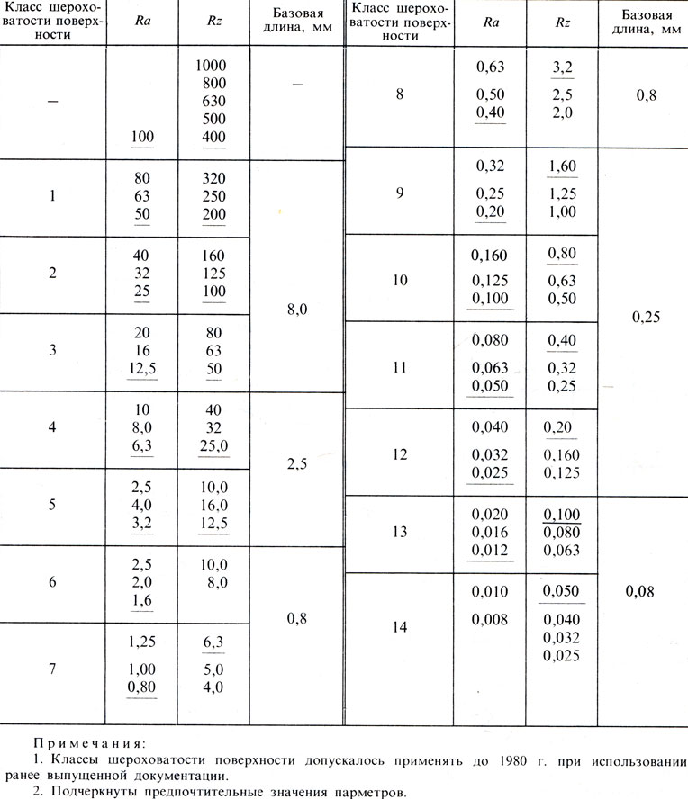
To assess the roughness, various indicators are used. Let's dwell on two main ones: Ra and Rz, indicating the height parameters of roughness according to GOST 2789 - 73 (ST SEV 638-77); Ra - arithmetic mean deviation of the surface profile; Rz - the height of the profile irregularities at ten points.
Surface roughness is classified according to numerical values parameters Ra and Rz with normalized base lengths in accordance with Table. 2.
The rules for applying the designation of surface roughness in the drawings are established by GOST 2.309-73 (ST SEV 1632-79).
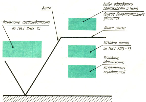
The structure of the surface roughness designation is shown in fig. 42. When only the values of the roughness parameter (Ra or Rz) are indicated in the designation, the sign shelf is not entered.
To indicate the roughness of surfaces, the signs shown in Fig. 43.
To indicate the surface roughness, the type of processing of which is not established, a sign is used (Fig. 43, a).
To designate the surface that should be formed by removing a layer of material, a sign is used (Fig. 43, b).
To designate a surface that should be formed without removing a layer of material or kept in the state of delivery, a sign is used (Fig. 43, c).
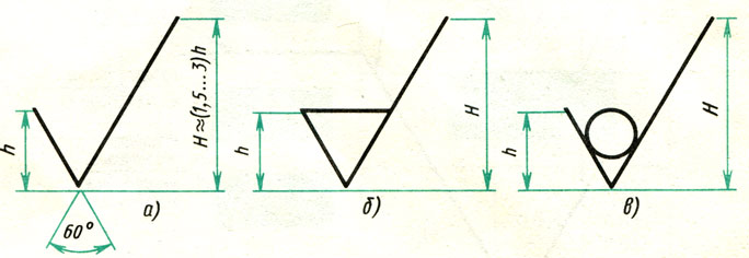
The height h of the characters should be approximately equal to the height of the digits of the dimensional numbers. The height H is taken 1.5 - 3 times more than h (see Fig. 43, a). The thickness of the lines of signs should be approximately equal to half the thickness of the main line.
The value of the roughness parameter Ra or Rz is placed above the sign; for the Ra parameter - without a symbol, for example, 25; for the parameter Rz - after the symbol (after the letter designation), for example, Rz 50.
If the base length corresponds to the value of the parameter according to GOST 2789 - 73, then it is not indicated in the roughness designation.
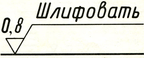
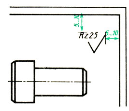
The surface treatment method is indicated only in cases where it is the only way applicable to obtain the required roughness (Fig. 44).
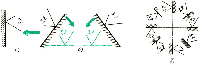
Roughness designation signs should touch the treated surface with a tip and be directed towards it from the processing side (Fig. 45).
In order not to be mistaken in the designation of roughness for different arrangements of surfaces, one can be guided by the rules for applying dimensional numbers given in § 5 (see Fig. 23). When indicating the surface roughness shown in the drawing by a vertical line, the designation is read on the right (Fig. 45, a). If the line is inclined, then the designation is applied so that it is in a normal reading position when the line "falls" into a horizontal position (Fig. 45, b). Examples of the location of signs are given for reference in fig. 45, c.
If all surfaces of the part have the same roughness, then the designation is placed in the upper right corner of the drawing (Fig. 46), placing it at a distance of 5-10 mm from the frame.
If the roughness of a part of the surfaces should be the same, then in the upper right corner of the drawing the designation of this roughness is placed and next to it is the sign taken in brackets (Fig. 47). This means that all surfaces that do not have a roughness designation or a sign on the images must have the roughness indicated in front of the bracket.
The size of the sign in brackets must be the same as the size of the signs printed on the images. The dimensions and thickness of the lines of the sign in front of the bracket are taken approximately 1.5 times more (see Fig. 47).
If some of the surfaces are stored in the state of delivery, then a sign is placed in front of the designation in the upper right corner of the drawing (Fig. 48).
The designation of surface roughness in the image of the part is placed on the contour lines, extension lines (as close as possible to the dimension line) or on the shelves (see Fig. 47). The surface roughness of repeating elements of parts (holes, grooves, etc.) is applied to the drawing once (see Fig. 47).
Surface roughness, characterized by parameters from Rz 40 to Rz 320, is obtained by rough turning, filing with a bastard file (No. 1 and 0), etc. Surface roughness, which corresponds to parameters from Rz 10 to Rz 40 and from Ra 1.25 to Ra 2.5 is formed as a result of fine turning, filing with a personal file (No. 2), etc. Surface roughness, characterized by parameters from Ra 1.25 to Ra 0.16, is achieved by grinding and polishing. Higher values of roughness parameters are obtained by honing and other methods.
Answer the questions?

1. What does the designation affixed to the image of the surface of the part mean?
2. How should you understand the sign affixed to the drawing?
3. In what cases is the sign applied to the drawing?
4. In what case is the roughness designation placed in the upper right corner of the drawing?
5. How should the inscription in the upper right corner of the drawing be understood?
6. What is the size and thickness of the stroke of the signs indicating the roughness of the surfaces?
7. How are the signs , , , placed in relation to the designated surface?
8. What rules can be used to check the correct location of the roughness designation for different positions of the lines depicting the designated surfaces?
Assignments to § 6
Exercise 28
Answer the following questions in writing. 49 (do not rewrite questions):
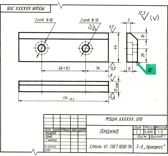
1. What is the name of the part?
2. What material should it be made from?
3. What is the scale of the drawing?
4. What types are given in the drawing?
5. Why are circles with a diameter of 18 mm drawn in the main view with dashed lines?
6. What is the roughness of the front and back surfaces, the distance between which is 15 mm?
7. What is the roughness of the surface marked with the letter in the green rectangle?
8. With what roughness should holes ∅ 10 be machined? ∅ 18?
9. What is the roughness of the surfaces, the distance between which is 134 mm?
Exercise 29
Redraw fig. 41 and 50, a. Give captions to these figures, in which you state the main provisions of § 6. At the beginning of the work, write the heading "Designation of surface roughness." As a result, you will receive a summary of § 6.
Exercise # 30
In fig. 50, and the surface roughness is applied correctly. In fig. 50, b out of nine cases of applying roughness marks, five are given with errors. Write down in your notebook what these mistakes are and how to do it right?
Recording example: the designation is applied on the reverse side. This sign must be rotated 180°.
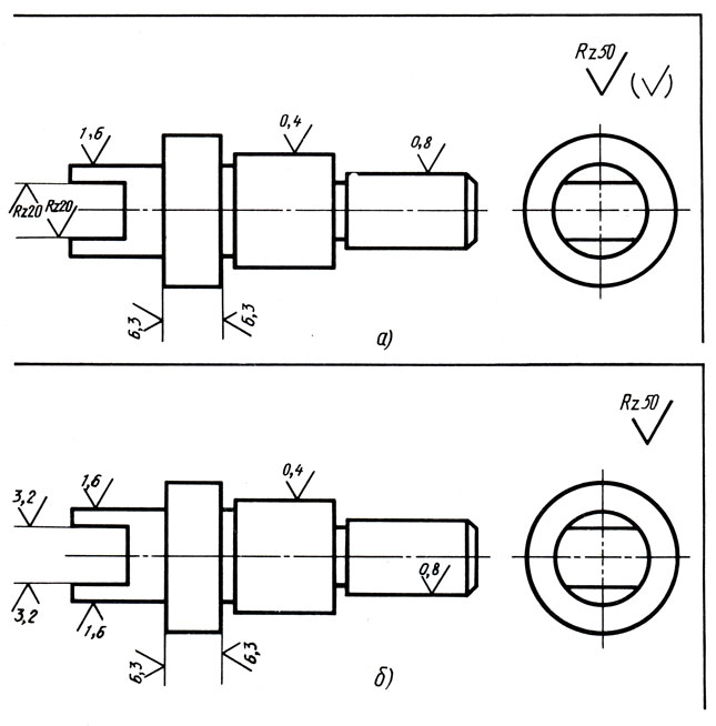
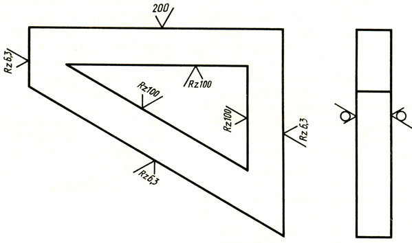
Exercise 31
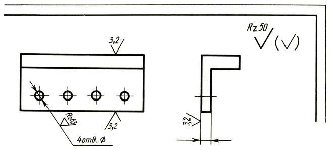
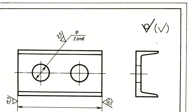
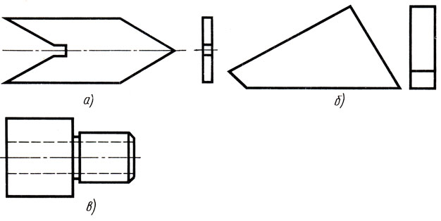
Redraw fig. 51, dimension and mark the surface roughness. Determine the dimensions by measuring the image. The surface roughness is as follows: in fig. 51, a - inclined surfaces Ra0.4, horizontal - Ra0.8, the rest Ra1.6 in fig. 51b; - inclined surfaces Ra25, horizontal - Ra50, front and rear surfaces are not subject to processing; in fig. 51, c - outer cylindrical surfaces Ra12.5, hole surface Ra3.2, the rest (including the groove surface) Ra25.
Answers to the exercises of chapter I
Go to exercise 1
A. Number 1 is the main view, number 2 is the left side view; number 3 - top view.
B. The drawing corresponding to the visual image is marked with the number 2 in a circle.
B. Direction C corresponds to the main view, direction A corresponds to the left view, direction B corresponds to the top view.
Go to exercise 2
A. Number 1 indicates the main view, number 2 - left side view, number 3 - top view.
B. The drawing corresponding to the visual image is marked with the number 3 in a circle.
C. Direction B corresponds to the main view, direction C - to the left view, direction A - from above.
Go to exercise 3
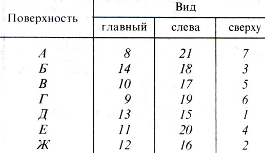
Figure A corresponds to drawing 2, figure B - drawing 6, figure C - drawing 5, figure D - drawing 5, figure D - drawing 4, figure E - drawing 7. (No answers were given to the rest of the assignment)
Go to exercise 4
Go to exercise 20
Rice. 34. Correct drawing shown in fig. 34, a. In fig. 34, 6, smaller sizes are drawn further from the images than large ones, so the dimension lines intersect with the extension lines. In fig. 34, in the axial and main lines are used as dimensional, which is unacceptable. In fig. 34, d two dimension lines are a continuation of the main ones. The intersection of the dimension and extension lines is allowed.
Rice. 35. Correctly dimensional lines are placed in fig. 35, b. In fig. 35, and most of the dimension lines are located inside the image, although it was possible to place them outside the image outline, as in fig. 35, b.
Go to exercise 7
Rice. 11. Example 1: distances between strokes are large; they should be 1-2 mm. Example 2: Stroke lengths vary. Examples 3 and 4: the length of the strokes is different and the distances between them are not the same.
Rice. 12. Example 1: distances between strokes are large; they should be 3-5 mm. Example 2: Stroke spacing is not the same. Example 3: different stroke lengths. The distances between them are not the same. Example 4: the length of the strokes is not consistent, it is not the same.
Go to exercise 8
Example 1: The dashed lines must start with dashes and the centerline must extend beyond the outline of the image: Example 2: The strokes at the corners must meet. Example 3: The strokes of the dashed and dash-dotted lines must intersect with each other and with the main lines.
Go to exercise 9
Example 1: The center lines must intersect at the center. Example 2: Center lines do not extend beyond the circle. Example 3: Centerlines are missing. Example 4: Center lines extend beyond the circle by more than 5 mm.
Go to exercise 10
The tools shown under numbers 3, 5, 6, 7, 9 are correctly prepared for work; number 5 shows the sharpening of the lead with a "spatula" for drawing solid main lines, and number 6 shows the sharpening of the lead for drawing thin lines.
Go to exercise 21
Dimensional numbers are correctly written in Fig. 36, d. In fig. 36, and near the dimensional numbers the units of measurement are indicated - millimeters. Linear dimensions applied in millimeters without indicating units of measurement. In fig. 36, b, the dimension numbers are not placed at the middle of the dimension lines, but on the side. In fig. 36, in all numbers are located under the dimension lines, and not above them.
Go to exercise 22
The dimensional numbers are correctly applied in Fig. 37, c. In fig. 37, and the numbers 65, 18 and 19 are reversed. In fig. 37, b, the numbers 18 and 19 are located not above the line, but below it. The numbers 20 and 25 are applied so that they are not readable on the right; correct location see fig. 37, e. In fig. 37, d numbers 65, 18, 19 and 25 are not perpendicular to the dimension lines.
Go to exercise 23
Diameter and square designations are correctly marked in fig. 38, e. In fig. 38, and square and diameter signs are omitted before the dimensional numbers. In fig. 38.6 instead of the size ∅30, R15 is written. You can't do that. No square sign. In fig. 38, d, R30 is written instead of ∅30, which is a mistake. There is no error in drawing the size of the square.
Go to exercise 24
Correctly done Fig. 39, a.
In fig. 39, b, the dimension ∅10 is repeated four times. It is more rational to write down: 4 holes. ∅ 10 (see Fig. 39, a). Instead of the letter s before the number 3, it says "thick". In fig. 39, in front of the number 10, the entry "4 holes." and the sign ∅ , and there is no letter R before the number 15. The letter s is missing, explaining that the number 3 indicates the thickness. In fig. 39, d four times repeated size R15 (one size R15 is enough). The dimensions coordinating the position of the holes are given between their edges, and not between the centers.
Go to exercise 25
Rice. 40 a. Examples 1,3,6, 7 were made without errors. In examples 2 and 4, the maximum deviations of +0.1 and -0.2 should be written in a font size smaller than the numbers 31 and 33, and placed respectively at the top and bottom. In example 5, the number 0.3 should have been written once and the same value as the number 32. In examples 8 and 9, the maximum deviation of 0.1 with a minus should be written at the bottom, and 0.2 with a plus at the top.
Go to exercise 28
Answers on questions.
1. The item is called "Plank".
2. The part is made of steel grade 45 GOST 1050-74.
3. Drawing scale 1: 2.
4. The drawing shows the main view, the top view and the left view.
5. Circles with a diameter of 18 mm are drawn in the main view with dashed lines, because they are on back side details are invisible.
6. The front and back surfaces of the part, the distance between which is 15 mm, should have a roughness of Ra1.6.
7. The surface marked with the letter a in the green square must have a roughness of Ra3.2.


How to understand: will the kitten be fluffy?
What light alcohol can pregnant women drink: consequences of consumption
Why do legs swell in the ankles and ankles of feet in pregnant women: causes and methods of treatment
The wedding of Prince Harry and Meghan Markle: scandalous and secret details of the marriage (photo) Future marriage of Prince Harry year NTV
How to close white plums for the winter