Page 1
The tailstock quill is moved by a hydraulic cylinder controlled by a handle located on the hydraulic tank. Inside the headstock housing there are two hydraulic cylinders that are used to secure the quill; when the center of the tailstock rests against the product, oil enters these cylinders and they clamp the quill.
The tailstock quill moves from a hydraulic cylinder attached to the headstock body. The quill is fastened automatically after the center of the tailstock enters the center slot of the part. It is carried out with the help of two hydraulic cylinders, pulling together two pairs of crackers, pressing the quill to the headstock body. The tailstock spindle rotates in rolling bearings that are lubricated with grease. The center is knocked out using a special wedge through the oblong holes in the headstock and quill body.
The tailstock quill is moved by a hydraulic cylinder.
The tailstock quill is folded back. At the end of the stroke of the piston 17, air through the hole in the pneumatic cylinder 16 enters the cylinder 19, which feeds the blanks to the center line. At the same time, air is supplied to the self-propelled shutdown valve 14.
The tailstock quill is connected by a linkage system to the hopper gate, which ensures the hopper is opened at the beginning of each cycle.
The tailstock quill is lubricated through nipples 13 and 14 with Turbine-22 oil. The quill is lubricated at least once a shift. Roller guide keys of the lead screw are packed with CIATIM-203 grease at the factory and do not need lubrication during operation. The feed gears are lubricated by leaks from the hydraulic motor.
The tailstock quill, which has a positioning movement depending on the length of the tap to be machined, has movement only along the axis.
The tailstock quill is pressed by a spring, the force of which depends on the distance rear center from the workpiece. The position of the rear center is adjusted by moving the headstock along the bed guides.
Pull out the tailstock quill by 80 - 100 mm and fasten.
The tailstock quill, for the sake of ease of maintenance of the machine, is advisable to move by means of a handwheel located on the front side of the machine.
The tailstock quill has the largest longitudinal movement by 40 mm, and the headstock spindle by 5 mm. The cutting tool is strengthened in the collet, and the workpiece is strengthened in the collet of the headstock. Handwheel 2 is used to clamp the collet with the cutting tool and feed the quill. Handwheel 3 is used to clamp the collet with the workpiece. When the cutting tool is pressed on the workpiece, the headstock spindle moves to the left side, and the left pulley 4, on which the straight belt is put on, turns on the spindle rotation to the right side at a speed of 820 rpm. After threading, the translational movement of the cutting tool is delayed. The spindle of the headstock moves to the right side, and the right pulley 5, on which the cross belt is put on, imparts left rotation to the spindle at a speed of 1300 rpm. The tap is unscrewed from the workpiece.
The tailstock quill travel is 150 mm, which allows installation of short and long parts without rearranging the tailstock.
The tailstock quill can only be retracted when the grinding headstock is retracted.
Instructions for work
"Disassembly and assembly of the lathe tailstock".
I. Rules for safe work.
You can only use a properly functioning tool of the appropriate size Use of spacers if the key is larger than required, as well as extension of the key handle with tubes or other objects is prohibited, as this can lead to slipping of the tool
ument and injury.
It is not allowed to start work without familiarizing yourself with the tailstock device according to the drawing.
Before starting work, prepare a place for placing the parts. Small parts are put into the box of the tailstock quill, which must be carefully protected from dirt and dust.
The hammer may only be used with the permission of the teacher. Under no circumstances should the chisel be used to loosen bolts and nuts.
For the correct assembly of the tailstock, it is necessary to imagine its structure and the interaction of individual parts, as well as to know well the sequence of disassembly in order to be able to assemble in the reverse order.
Fig. 1. Lathe tailstock: 1, 14 16, 18, 24 - screw; 2, 7, 19, 21 - nut; 3 - quill; 4 - case; 5 - handle; b - power screw; 7 - nut; 8-head; 9 - limb sleeve; 10-spring; 11 - flywheel; 12-washer; 13 - key; 15 - handle; 17 - plate; 20 - key; 22 - diameter; 23 - bolt.
Tools spanners 12, 10 and 8 mm, screwdriver 5 mm.
Sequence of work.
1. Become familiar with the tailstock device according to the drawing.
2. Unscrew the nut 21 from the bolt 23 and, lowering the cross-section 22 together with the bolt 23 down, take them out and put them on the workbench.
3. Remove the headstock together with the bottom plate 17 and transfer to the workbench.
4. Rotate the handwheel 11 until the quill 3 with the nut 7 come off the power screw 6, then remove the quill.
5. Unscrew screw 14, remove washer 12 and flywheel 11 with dial 9, spring 10 and handle 15.
6. Remove the limb bushing 9 from the flywheel 11 and remove the spring 10 from it.
7. Remove the key 13.
8. Unscrew the screw 16 and take out the head 8, as well as the power screw 6.
9. Unscrew screw 1 and unscrew nut 2 from it.
10. Take out the handle 5 with crackers and remove the crackers.
11. Unscrew screw 18 to move the tailstock body 4 laterally.
12. Unscrew the screw 24, which connects the headstock body to the plate 17.
13. Disconnect the body from plate 17, remove nut 19 and key 20.
14. Wipe all parts with a rag.
15. Lubricate the friction surfaces with a thin layer of grease.
16. Assemble the headstock and install it in place.
III. Tasks.
1. Determine the pitch of the tailstock screw.
2. Determine the greatest possible displacement of the tailstock housing relative to the plate.
IV. Review questions.
1. How to prevent self-unscrewing of the quill?
2. What is the purpose of the spring, which is installed in the limb sleeve?
3. What is the nut on the screw for?
Instructions for work.
"Setting up the machine and processing the outer cylindrical surface".
I. Rules for safe work.
Before starting work:
1) fasten all the buttons so that there are no hanging parts of the clothes that can be caught by the rotating parts of the machine; remove hair under the headdress;
2) familiarize yourself with the location of buttons and control handles and the purpose of each of them;
3) check that all controls are off or in neutral.
During work, it is prohibited:
1) lean on the machine;
2) switch the belt transmission on the fly;
3) switch gearbox and feed box on the go;
4) leave the machine unattended;
5) stop the chuck by hand after turning off the machine;
6) measure the part on the fly.
Failure to comply with these guidelines could result in an accident.
Remember that the Stop button is colored red.
1. Install the chuck in the spindle, for which do the following: wipe the thread at the end of the spindle and in the chuck hole with a rag and lubricate it with oil; screw on the cartridge; secure the chuck against self-loosening.
2. Install the turning cutter by doing the following: wipe the center and hole in the tailstock quill with a rag, set the center to the tailstock; bring the tailstock to the support; using a set of shims, set the cutter through so that its top coincides with the top of the center (there should be no more than two shims, they should not be shorter than the part of the cutter that is fixed in the tool holder, the overhang of the cutter should not exceed 1.5 times the height); fix the cutter.
3. Check the conformity of the dimensions of the workpiece to the dimensions specified in the drawing.
4. Fasten the workpiece.
5. Adjust the machine to the specified operating mode.
Switch on the machine.
7. Bring the tool in contact with the workpiece.
8. Move the tool with the support to the right.
9. Set the cutter to the specified cutting depth; align the zero division of the dial with the line on the fixed screw sleeve; Determine the scale division of the dial, turn the cross feed screw in accordance with the specified cutting depth.
10. Sew the belt with a length of 5.7 mm.
11. Stop the machine.
12. Check the dimensions of the workpiece with a vernier caliper.
13. Roughly grind the workpiece using manual feed.
14. Set the tool to the desired depth of cut for fine turning.
15. Grind the workpiece clean using the power feed.
16. Stop the machine.
17. Check the size of the workpiece with a vernier caliper.
18. Remove the part and the cutter.
19. Tidy up the workplace.
III. Review questions.
1. Why is the cutter overhang length limited?
2. Why is it not allowed to fix the cutter with one bolt?
3. How to eliminate the possibility of self-unscrewing of the chuck?
The results of experimental testing of the optimal teaching model for students in grades VII-VIII in the process of working on screw-cutting lathe
The experimental base of qualification work to test the designed model of the process of teaching students of the 7th-8th grades to work on a screw-cutting lathe is school No. 5, item of the Oktyabrsky Krasnoarmeisky District of the Krasnodar Territory.
The pedagogical experiment was attended by Doctor of Pedagogical Sciences, Professor Shchekoldin A.G., Doctor of Pedagogical Sciences, Professor Zarechnaya L.P., Ph.D., Associate Professor Zinoviev A.I., Ph.D. Sci., Associate Professor Radchenko N.V., Ph.D. Sci., associate professor Makhnenko A.Ya., candidate of pedagogical sciences, associate professor Zarechny A.V., senior teacher Ilyinykh A.P., director of secondary school No. 5 - Maksimenko Nelly Pavlovna, deputy directors for educational and educational work, teacher technologies - Mishchenko Andrey Eduardovich, student of the Faculty of Technology and Entrepreneurship Lukyanchenko DA, students of the VIII "A" class - 12 boys. A total of 29 people took part in the experiment.
The experimental work was carried out in the process of passing pedagogical practices. The experimental work consisted of ascertaining and formative experiments.
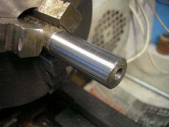
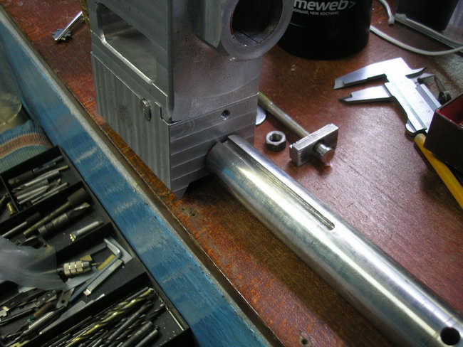
Homemade, quill will also be unique in its kind. No, the quill will be the most common one, just made not according to the factory dimensions, which, incidentally, I have never seen, but according to those calculated by me.
The protrusion of the quill from the headstock body should be about 50-70 mm, its diameter should ensure the installation of the tool with KM # 2. Based on this condition, I will make a quill from a calibrated circle of f30 and a length of 130 mm. Therefore, in the headstock body you need to make a stepped through hole, in the wide place of which the quill will actually be placed, the tail of the propeller will pass in the narrow one, and the supporting collar of this very screw will abut against the step through the bearing.
Moreover, the quill should be maximally coaxial with the spindle axis of the machine, as well as have a minimum backlash in conjunction with the body, i.e. sliding fit.
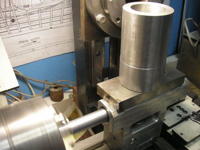
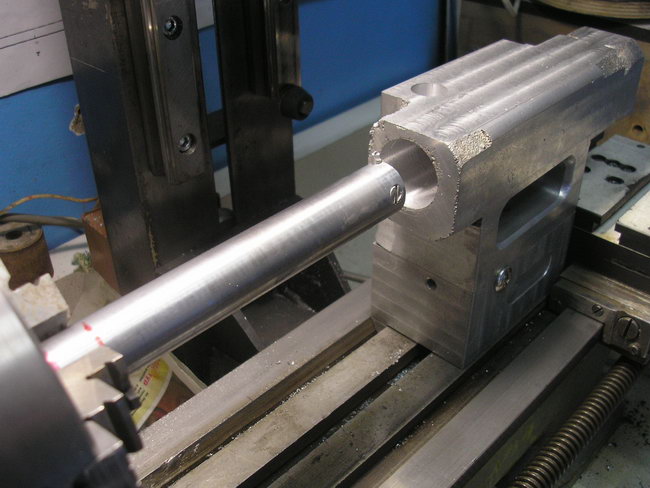
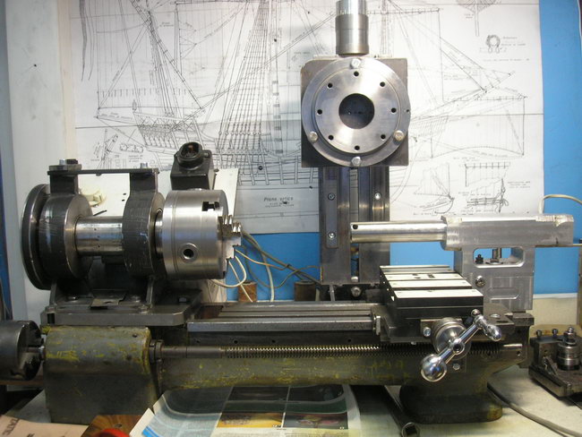
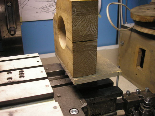
To solve this problem, I decided to make a hole directly on the machine bed, installing the necessary tool in the spindle (chuck), and attach the quill to the support and, in a tightened state, move it back and forth to the guides.
Once again I verified the installation of the headstock by measuring the misalignment with the bed guides in two mutually perpendicular planes:
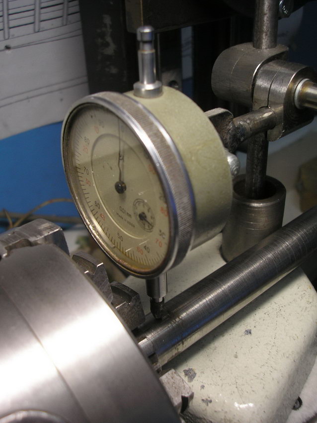
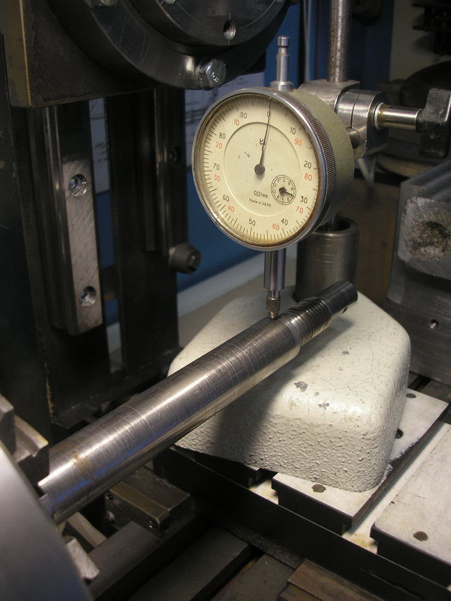
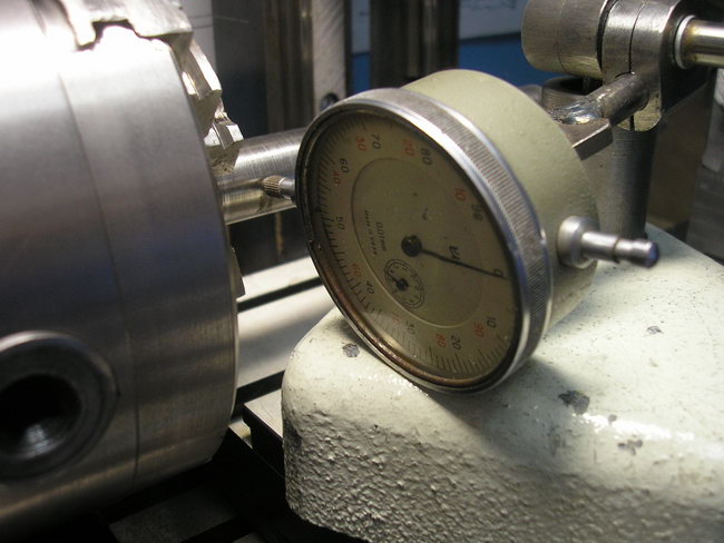

And after making sure that it was in the correct position, he proceeded.
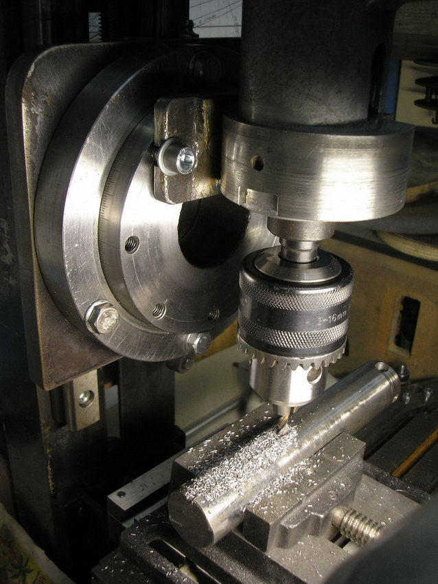
First of all, I drilled through the headstock with the longest drill in my arsenal, diameter 17.5mm. Not a joke, but the body length is no less than 174 mm. Before drilling, I tightened the headstock fixing nut, and by loosening it a little, achieved such a moment that the headstock, together with the support, began to move tightly, and rotating the flywheel of the lead screw pulled this coupling onto the drill and back.
After that I drilled to a depth of 145 with drills: 19; 21 and 22mm
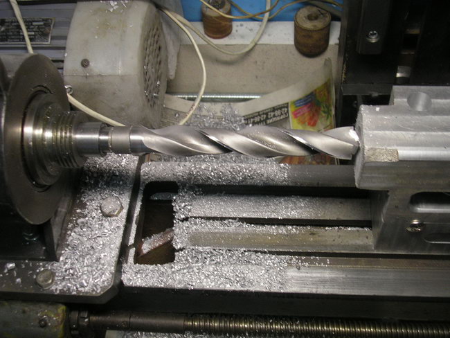

Of course, it was possible to drill immediately with a large drill, but since I still have the same spindle speed (about 900), so I had to use step drilling, i.e. increasingly.
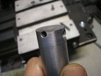
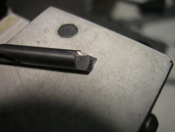
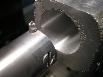
For further boring, I made a boring bar from the existing round timber of diameter 22mm. At one end, I drilled a 4mm hole at an angle, for the installation of a carbide centering tool, perpendicular to which I installed a clamping screw.


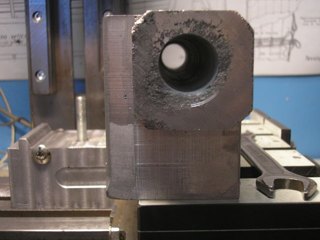
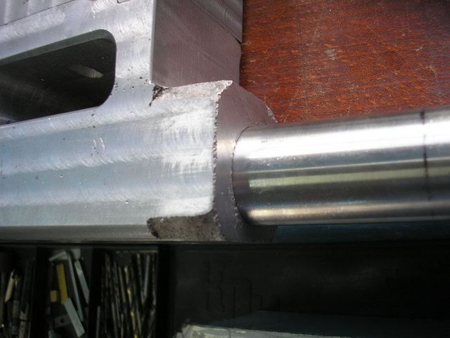
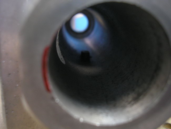
And setting the cutter by 1-1.5 mm per pass, he bored the hole to f29.4. Then, after thoroughly cleaning the machine and the base of the ST, he oiled it and prepared for a clean cut. The chisel cut on the smallest diamond. The task was somewhat facilitated due to the fact that under the quill itself the hole was only 132mm. in depth.
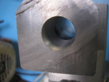
The first time I went about 0.4 and faced the problem of measuring the hole.
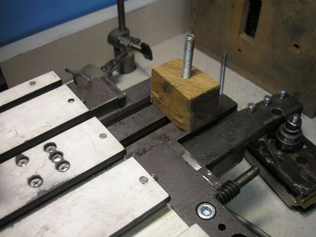
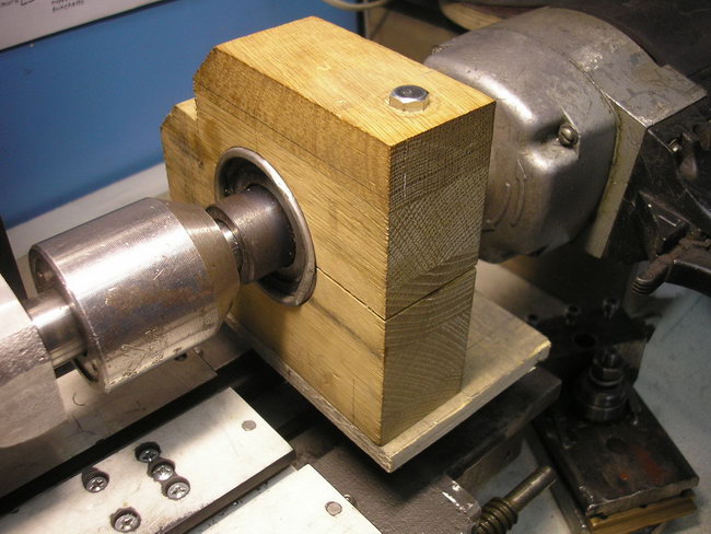
As a measuring plug, I found a bearing with an outer diameter of 30mm, and since more than anything, it was not possible to undermine for measurements, gradually pushing the cutter forward began to make trial strokes on a length of about 6mm. As soon as my plug entered the hole, I made a full pass, loading the headstock from above with whatever came under my arm in order to press the headstock to the bed as much as possible and reduce vibrations to a minimum. The caliper was very tight, the feed was done as little as possible so that the surface was as smooth and clean as possible, and the process took about 20 minutes, or maybe more. And oh God! I managed!
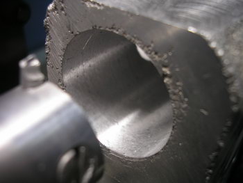


The process took about six hours, but it was worth it!
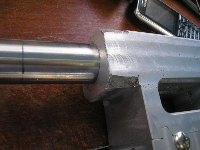
The quill fits into the case freely, but without any noticeable backlash. At the same time, the processing purity is surprisingly very high and no longer requires any refinement.
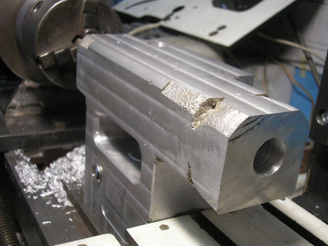
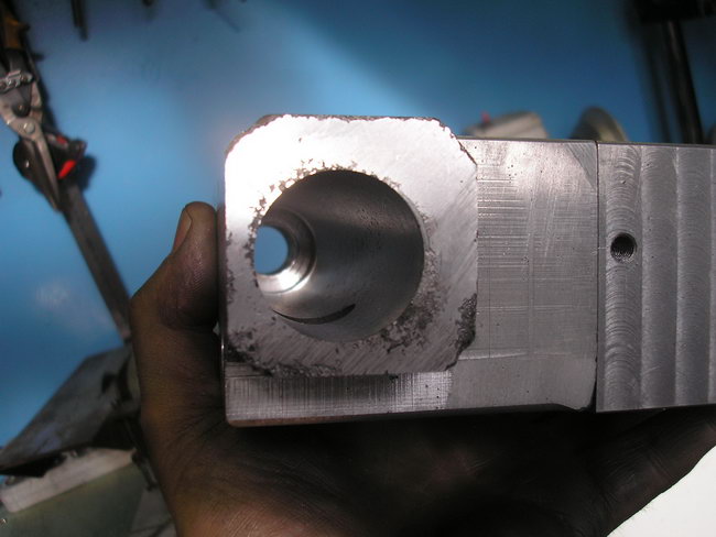
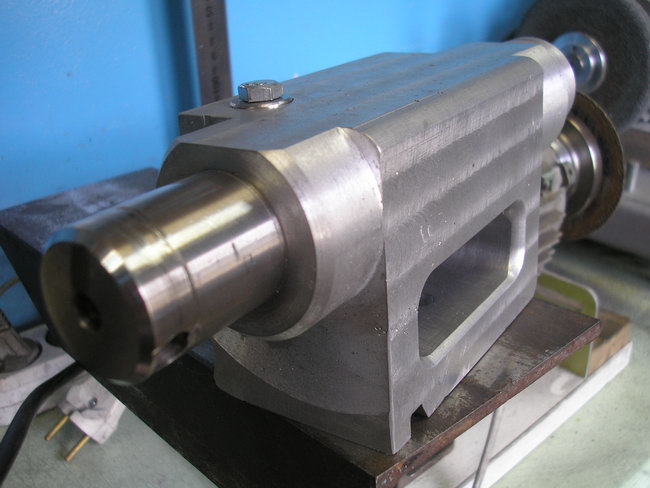
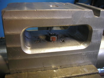
Finished with the tailstock body today, giving it a more aesthetic look.
He bored out the right side with a longer boring bar with a thin end.

removed the minimum layer, to cleanliness. Subsequently, I will press a bronze bushing here.
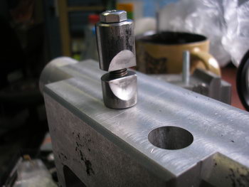
Made the parts of the jamming device:


I inserted the blank quill and tightened the wedges.
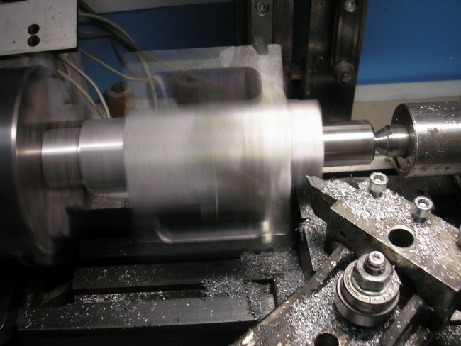
Made another temporary fixture to set the center of rotation to grind the body.

The quill was fixed in the cartridge, the right side was centered.

Using a longer bolt, I secured the counterweight to the jammed cracker.

Then he turned over the body and processed the left side ...
Removed the center and tweaked the right one.


I finally finalized the headstock scheme, deciding to lengthen the quill as much as possible:
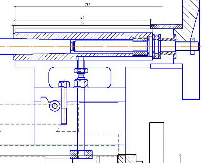
The quill turned out to be 20 mm. longer, so I had to bore the body again after spending almost half a day.
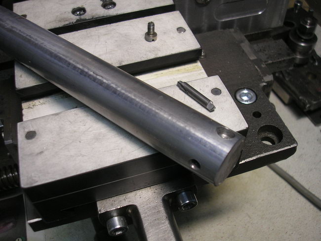
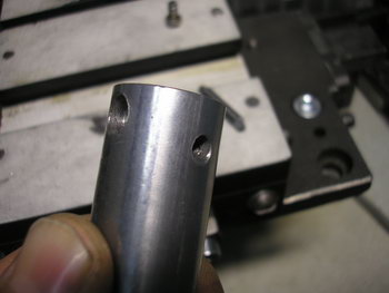
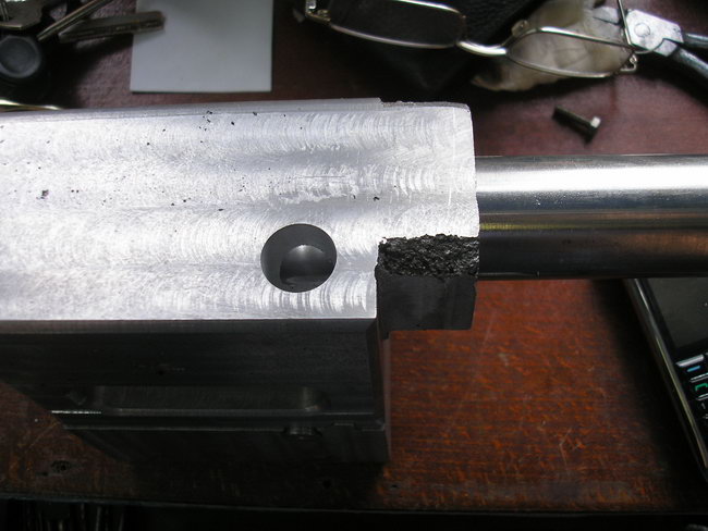
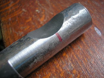
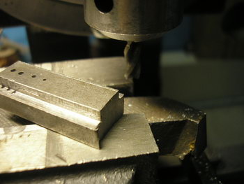
Then, having installed a large drill with a 5 mm cutter on the column, I made a groove to a depth of 4.

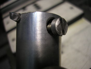
I made a key that prevents the quill from turning, I drilled the body, cut the M8 thread, screwed in the key and locked it.

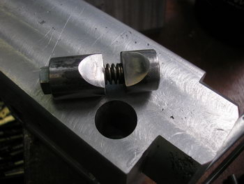
I picked up and installed a spring between the wedges
I milled the tie rod slider and checked the fixation on the bed ...

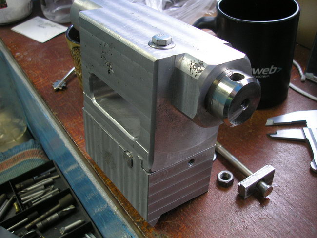
Now the working reach of the quill will be 80mm.
In fact, the working reach of the quill was only 70mm. The overhang is determined by the length of the threaded part of the screw, which is calculated so that when the quill is pushed into the body of the quill at the last two or three revolutions, the screw pushes out the tool. But if, for example, a center of rotation is installed in the quill, then it can be released outward up to 110mm and it will be securely fixed with wedges.
The design of lathes provides for the use of certain equipment. Only with the necessary equipment can you make a part with the necessary parameters accuracy. In this case, you need to purchase special equipment or make a homemade version. It is worth noting that you can not create everything for precise turning with your own hands.
Turning centers
Fixation of workpieces
Turning on lathe occurs by attaching it to jaw chuck, which transfers rotation and at the same time holds it in place. Such a device is effective when turning cylindrical bodies. In this case, the cutter is fed perpendicularly, which allows the metal to be cut to the desired diameter.
When considering a metal lathe, it should be borne in mind that many homemade and industrial versions have a structure in the back to support the workpiece and perform other tasks. Homemade look The metal lathe also has a headstock version, which requires special equipment.
Thus, when fixing on two opposite sides on a lathe, the tailstock and the headstock, the workpiece will be in a given position during the occurrence of even a heavy load.
When considering the tailstock, the following features should be noted:
- The device in question is intended only for attaching special equipment. The types of equipment used on a lathe determine the purpose of the tailstock: it can serve both for fixing a cylindrical body and for processing.
- In order for the workpiece not to change its position at the moment of strong feed or at high revolutions, the center is used, which determines the purpose of the tailstock.
- You can make a center with your own hands or purchase it in a specialized store. At self-production it should be borne in mind that the workpiece must be a solid solid metal with an increased strength index. This is due to the method of fastening: the quill presses the part against the spindle at the end and throughout the entire time the tip contacts it, there is little friction.
- The position of the lathe quill is adjustable only in the longitudinal direction. Given this feature, it is worth remembering that the position of the center must coincide with the axis of rotation of the spindle. Otherwise, rotations will occur with beating.
The considered device can also serve for drilling end holes and for solving other technological problems.
Fastening at two ends
Fixation at two ends occurs in the following cases:
- The industrial-type metal lathe has a speed control. The high speed of rotation that is transmitted to the part causes the part to "wobble". With precise processing, according to GOST, such a phenomenon leads to a rather large error.
- The large length and weight of the workpiece also necessitates the use of a tailstock. Under its own weight, the cylindrical body can deform and the metal cutter will "beat" during the feed of the cutter.
- Excessive cross feed may occur depending on the turning mode and the spindle speed. When processing a part in such a situation, it is rather difficult to make it with high accuracy.
In such cases, fixation should be carried out at both ends.
Types of turning centers
Commit the necessary tool you can do it yourself in quills. This work will take a few minutes to complete, and you can do it yourself. According to GOST, the following types can be distinguished:
- persistent. GOST specifies that the tip and the shank have practically the same diameter. The device of this design determines that the tip is made of hardened steel or hard alloy in accordance with GOST 13214-79.
- the fungal variant is somewhat different from the previous one. the mushroom tip has, according to GOST 8742-75, a larger diameter with a truncated working cone. according to GOST 8742-75, there are two types of tip that the fungal center possesses: with a centered roller or with a nozzle for it. the mushroom tip allows the device under consideration to be used for attaching bodies of revolution with hollow end holes during machining.
When turning at a time of high centrifugal force, the most favorable conditions can be made by using a center in the design of which there is a bearing. Such equipment can be different: the mushroom or thrust center also has a bearing.
The taper angle can be 60 or 90 degrees. The angle is selected depending on the cutting mode.
There are more complex types of accessories for installation in quill, which can have, for example, a device for measuring downforce. It is impossible to make some options for centers for a lathe with your own hands. The retraction of the spindle does not affect the use of the quill.
Download GOST 8742-75 "Rotating turning centers"


 Future marriage of Prince Harry year NTV")


Energy drinks: give vigor, but take away health What will happen if you drink 4 energy drinks
Mustard for weight loss: how to use the seasoning with maximum benefit Is it possible for children to have mustard
The benefits and harms of mustard for the human body Table mustard benefits and harms
How to treat the ear after piercing: types of antiseptics, their composition, rules and features of the treatment of a pierced ear
Sistine Chapel in the Vatican: description, history, architectural features