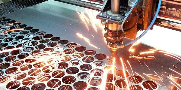
Convenience and precision laser cutting recognized by everyone who had the opportunity to order such cutting work sheet material... However, it should not be forgotten that the high speed and low cost obtained when cutting the material using a laser complex with a numerical program management, has its own explanations. In order for the CNC program to accurately follow the route it needs, laser cut drawings are required. It is they who ensure the maximum accuracy and sequence of processing complex contours of parts located on the workpiece sheet.
The cost of making blueprints for laser cutting
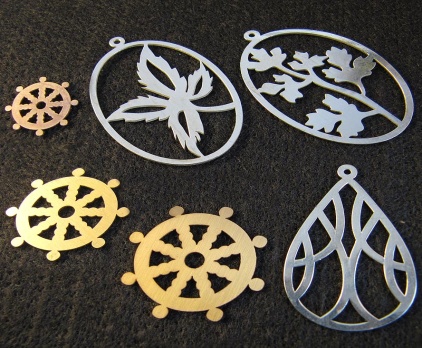
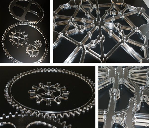
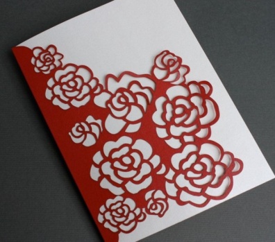
Send a requestPhotos of works on drawings for laser cutting
HOW WE ARE WORKING
The client sends the drawing by email
At a scale of 1: 1 in dwg, dxf format, AutoCad 2007 software (later versions excluded) indicating the material and quantity of parts, then the order value is calculated automatically (a special program is used) and a commercial offer is developed.
Sent drawings in other formats or CorelDraw13 (no later version) or a scanned drawing of the product increase the processing time and cost of the order.
The client leaves his coordinates
(phone number for a call) or arrives at the office at the agreed time for a more accurate discussion of the order.
The company is calculating the cost
The minimum order amount is 5000 rubles.
The client makes an advance payment of 50%
From the cost of laser processing and brings your material.
The company informs about the readiness of the order,
As a rule, the production time is from 1 to 5 days (depending on the volume);
The client pays the remaining 50%
And takes the order (pickup).
Customer Feedback on Laser Cutting Drawings

Dmitry Anatolievich.
I wanted to order a beautiful brass engraving on a plate in front of the office entrance. I turned to Lumus Laser - they were able to help. We selected the fonts together and agreed on the layout. I am very pleased with the engraving. Now our company has the most beautiful sign in front of the doors. The neighbors are jealous.

Sergei.
Not so long ago I had to fulfill an urgent order for the design of a shop window. Since there were many non-standard patterns and elements in the project, I ordered laser cutting from Lumus Laser. Everything was done quickly and efficiently. He just brought the blueprints and they cut the plexiglass accurately and inexpensively. Recommend.
Favorable prices for drawings for laser cutting
The programming procedure for cutting sheet material is not too complicated, but it requires vector files. dwg format, dxf, drawings for laser cutting. Also, the program that controls the operation of the cutting machine accepts drawings in the specified formats. If your designer or artist works in any other format, then the drawings will need to be converted to one of the above formats. It should be borne in mind that when converting a drawing, some distortions or accidentally added construction elements may sometimes occur.
Order the production of drawings for laser cutting from the company "LUMUS LASER"!
Despite the fact that, if necessary, unnecessary elements can be removed after some actions performed by the operator, it is best to prepare drawings in advance in one of the recommended formats. Moreover, almost all professional designers own the AutoCAD program. Since the laser complex for cutting sheet material works out any movements specified in the program and, if desired, can cut material with a cutting width of up to 0.2 mm, it is very important that the drawings for laser cutting of metal are executed correctly. This applies not only to the file format, but also to the drawing itself. In addition, the designer responsible for the drawing will need to take into account a number of important details.
- The drawing is carried out on a scale of 1: 1.
- The machine does not know how to recognize the scale, therefore, it cuts the material only in such a size (scale), which is set earlier in the drawing.
- If you want to cut several identical parts on a sheet of material, it is enough to provide a drawing of one single part, and the operator who controls the machine himself clones and places copies of the part on the material.
- The program does not recognize bitmap images. Vector images only.
- In the drawing, a gap of at least the thickness of the material is required between the parts.
- If you are preparing drawings for laser cutting plywood or some other material, you cannot use color fill.
If you need a very accurate part size, keep in mind that the machine makes a cut with a width of 0.35 mm when cutting, so the drawing for especially precise parts is indented in the right direction by this width.
1. Creating a layout for laser cutting So, you are going to make a layout of the product that you want to cut out on a laser machine. How to do it?
Let's say you want to make a batch of numbers for a wardrobe. First you need to imagine how the number will look like, maybe even draw those. sketch. Let it look like in Figure 1. Small, rectangular, with rounded corners, measuring 4 by 5.5 cm, with an engraved number.
Now you can start layout in CorelDraw.
First, let's create the shape of the number itself: this is a rectangle with rounded edges and a circle for the hole:
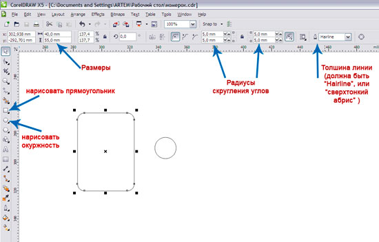
Special attention: Line thickness - Hairline, or "super thin outline" in the Russian version. Fills - no. The line color is black. 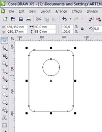
Now drag the circle onto the rectangle where the hole should be. To align the hole in the center, select both the rectangle and the circle and press the Latin "C" key (or Arrange -> Align and Distributive -> Align center).
Now you can combine everything into one curve: select everything and press ctrl + L
Everything. The layout of the number is ready, and you can already save and cut, but we still need to engrave the number. And it's too long to do them one at a time.
So the number:
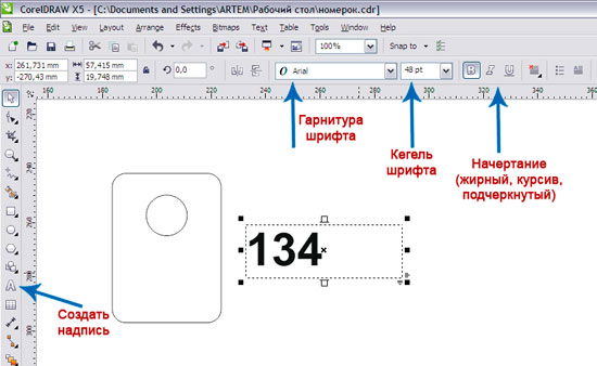
After creating a number of the desired size, place it on the number.
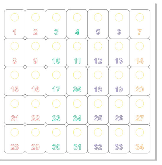
We do not plan to make one number, for example, we need 35. And making them one at a time is too long, it’s easier to make a layout for all 35 pieces at once.
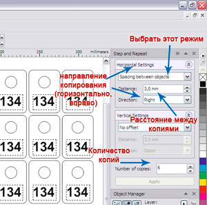
And, of course, you can manually draw all 35 pieces, but it's easier to copy our number 34 times, and even easier to use the Step and Repeat function (Edit-> Step and Repeat or just press ctrl + shift + D)
In the appeared docker (side window), enter the copy parameters: first 6 copies horizontally, and then copy the resulting line 4 more times downward.
Now we have 35 numbers with the same numbers. And we need different ones: from 1 to 35. So we manually change the text on all numbers.
Special attention: the minimum distance between objects depends on the material, but in any case should not be less than 1-1.5 mm. More details - in the second part, below.
So now we have a mock number plate. However, this model is not suitable for work on a laser machine, because does not meet a number of requirements.
2. Preparation of a layout for loading into a laser machine Conditions for preparing files for laser cutting and engraving:
The file should consist of curves. All numbers on our numbers are written in fonts, and they need to be converted into curves. Select all objects with a frame and right-click -> Convert to Curves (or just press ctrl + Q). 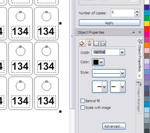 The thickness of all lines - Hairline (super thin outline) The thickness of the lines can be changed for each object manually, but we already have more than a hundred of them, so it's easier - through Object Properties. (This is also a docker, if you do not have it enabled, then Window-> Dockers-> Properties or just Alt + Enter) Select all objects, click on the tab with the feather, then set the thickness of the Hairline (see picture). The cutting contour and the engraving contour should be highlighted in different colors, the fill is transparent everywhere
 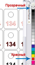 You need to select all the numbers and recolor them, for example, in red. To do this: select all the numbers. on the side panel of colors, right-click on red - the numbers will have a red outline with the left button, press on transparent (in the form of a cross) - all numbers will lose their fill Special attention: The machine does not distinguish all colors. For example, all shades of gray for him are black. Use primary colors: black, red, blue, green, yellow, lilac, cyan, orange, white.
Minimum Distance Between Objects - Below is a table of minimum clearances between parts. Material thickness Minimum gap Less than 1 mm, cloth or paper / cardboard 1.5 mm Less than 1 mm, plastic 2 - 2.5 mm 1-3 mm 3-4 mm 3-6 mm 4-4.5 mm More than 6 mm 5 mm and more Violation of these standards will lead to deformation of the cut edge.
There are also some important rules:
All lines in the file must not be transparent. The file must have one page, or all shapes to be cut must be placed on the first. All contours must be closed (if, of course, it is possible) in the case of cutting, and they must be closed in the case of engraving (engraving of open lines can be carried out only in the form of cutting not through and through). The model should be made on a 1: 1 scale, i.e. real size. If you plan to order an engraving, remember: the minimum size of a text symbol is 1 * 1 mm. If accuracy is very important to you (for example, in the manufacture of prefabricated structures), keep in mind that the beam thickness is 0.1 mm, i.e. if the file has a hole with a diameter of 5 mm, then in practice it will come out 5.1 mm. If all these conditions are met, then the file is ready to work. You can start cutting directly from Corel, having previously installed a special plug-in, or you can save the file in .plt format and load it into the specialized LaserCut program that comes with the machine.
3. Small tricks How to prepare a file so that it cuts faster? The figure shows some tricks.
Splicing contours. Parts can touch closely and have a common wall. For example, our numbers. Number 9 has a common wall with four other numbers, i.e. all of its walls can be removed, leaving only the rounded corners; this approach reduces the cutting footage by almost a third. And saves material. The color grading of the engraving: Laser engraving is done line by line: the head traverses a line from left to right, and then rises up and traverses the next line. Why did we color the numbers in different colors? To shorten the string. After all, the machine will not start engraving a new color until it finishes the old one. Those. if you fill them in one color, then the head will travel the distance along the entire sheet, and if done as in the figure, then it will first fluctuate between the first two columns of numbers, then between the third and fourth, i.e. the distance between the second and third will no longer be. This approach can cut the engraving time in half, and after all, engraving can take up to several hours. Cut order You can also mark the cut sections with different colors to determine the order of cut. For example, our holes are highlighted in yellow, and are cut in a separate cycle, first. This was done in order to exclude the possibility of marriage: if you first cut out the outer contour, then the number can fall out of the sheet and the hole in it will no longer be cut. different colours can be used, for example, for different cutting power settings: through and through and not through. Also different colors you can turn it on and off: now we cut the red blue and yellow outline, and the next run turns off the red and cut only the blue and yellow.
Good day!
Consider how from AutoCAD transfer data to a CNC machine for flat machining of a part or workpiece - 2D milling, laser cutting and laser engraving, etc.
NC programs for machine tools are created in special CAM programs, which can be stand-alone applications or integrated directly into the CAD system environment. However, most CAM programs support importing vector graphics in DXF format.
The sequence of preparing the file should be optional as shown here. But be careful - if you first delete all unnecessary layers and other objects, and then start exploding blocks, you may end up with unnecessary objects in the drawing. Also, the requirements and processing capabilities / limitations of the machine should always be considered.
2. Bring everything from paper space to model space
Description:
Almost all CAM systems only accept data from model space. If the image of your flat pattern was created in paper space, then transfer it to the model.
Solution:
For an image originally created in paper space, use the clipboard to transfer to the model. You can also use the command CHANSPACE (_CHSPACE) that moves the selected objects between model space and paper space. While in paper space, create at least one 1: 1 viewport. Run the command CHANGE, select the objects to transfer, the objects will be transferred to model space at the scale that is set for the current viewport.
3. Remove unsuitable elements from the drawing
Description:CAM programs and machines CANNOT work with points, blocks, regions, OLE objects, 3D polylines, shapes, etc. Get rid of them.
Solution:
- To locate objects in the drawing, use the command Quick selection (SELECT or _QSELECT)
- If points are not visible in the drawing, then change their appearance with the command DIALTTOCH (_DDPTYPE), now you can easily find and delete them
- Break blocks and areas with the command Dismember(EXPLODE or _EXPLODE)
- OLE objects, if possible, convert to native AutoCAD objects using the commands Convert (OLECONVERT or _OLECONVERT)... If it is impossible to convert, open the OLE object in its native application ( OPEN or _OLEOPEN), copy the necessary data in it and paste it into AutoCAD using the command Paste special (VSTSPETS or _PASTESPEC)... I wrote more about the special insert.
- It is not easy to convert a 3D polyline to a flat polyline. Despite the fact that CAM systems are very fond of polylines, in the case of a 3D polyline it is better to split it into segments using the Explode command (see above). Make the resulting segments flat (see point 4). Learn more about transforming polylines.
- To get rid of forms use the command PURGE (_PURGE)
4. Make the drawing flat
Description:
If you design a flat pattern in 3D using sheet metal body construction commands, you will get a flat pattern by projecting a 3D flat pattern. To avoid confusion, check if your drawing is flat by rotating it using a 3D orbit or viewcube. If the drawing is not planar, then convert it to a set of 2D objects.
Solution:
Use the command FLATTEN from the package. The FLATTEN tool creates a 2D representation of the selected objects and projects them onto the current view plane.
In addition, you can select all geometric objects and using the window Properties set the Z coordinate to 0.
IMPORTANT! If there are 3D polylines in the drawing, the FLATTEN command will make them flat, but the object type will not change. That is why 3D polylines need to be split into segments, and the segments should already be assigned the value of the coordinate Z = 0.
5. Get rid of double and superimposed lines
Description:
If, when drawing or converting in the drawing, double or superimposed lines and arcs are formed, then you need to get rid of them. When processing such geometry, the CAM system will accept all superimposed objects and create a processing path for each. In other words, if there are two superimposed segments in the drawing, then the machine will cut through this place with a laser twice, which is wrong and will lead to an increase in the cost of manufacturing.
Solution:
Use the command PURGE (_OVERKILL) to remove duplicate or overlapping lines, arcs and polylines. In addition, the command combines partially overlapping or adjacent elements.
IMPORTANT! Be careful with how the command merges adjacent objects. On the one hand, if you combine two touching collinear segments, the machine will make one cut, not two with two starts and stops. On the other hand, if you plan to cut on milling machine, then, perhaps, milling of collinear segments is planned using different tools or in different time... In this case, merging objects will render the geometry unusable.
6. Convert splines and ellipses to polylines
Description:
No machine can work correctly with splines and ellipses. CAM programs are great for polylines, which can be made up of lines and arcs.
Solution:
- To convert splines to polylines use the command REDSPLINE (_SPLINESEDIT)... I wrote about this in detail in this post.
- Convert ellipses to polylines, arcs, or lines. More details in the post.
note that different ways conversions give different accuracy, choose the appropriate tool and method in each case.
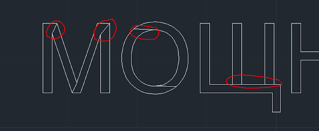
7. Convert all text boxes to curves
Description:
CAM-modules perceive each character of the text as a whole, so processing of such objects is impossible in principle. There is only one way out - convert the text to curves (polylines)
Solution:
To convert text to curves, use the command Explode Text from the package. The result of the operation - labels in the form of 2D polylines
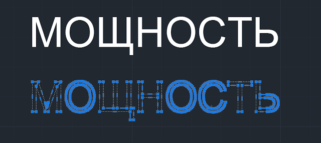
Pay attention to the peculiarity of converting texts performed to TrueType fonts - during conversion, unnecessary elements (artifacts) may be generated, remove them manually
8. The drawing must be in real scale 1: 1
Description:
The CAM program perceives geometry at a scale of 1: 1, so if you do not want to get blanks several times larger or smaller than necessary, then bring the image to a real scale of 1: 1.
Solution:
To find out the scale of the image, measure the length of one object with the command MEASUREGEOM (_MEASUREGEOM) and compare with the length that the object should have. To scale, use the command SCALE (_SCALE)... Attention! DO NOT measure the length of an object with the sizing command LINEAR because the dimension style can be set to a measurement scale other than 1.
9. Move everything into one layer
Description:
All common CAM systems are capable of working with only one layer of the drawing; other layers are simply ignored by the program. Bring the entire image into one layer, let it be a "standard" layer named 0. If for some reason it is impossible to use a 0-layer, create a layer with English name like CNC or flat_pattern.
Solution:
To transfer objects from one layer to another, select them and select the target layer from the list of available ones. You can also merge layers with the command LAYOBED (_LAYMRG)... After transferring objects, do not forget to remove unnecessary unused layers.
10. No other line types other than solid
Description:
All objects must be created with a solid line ( CONTINIOUS). If you create a segment with a dashed line, the machine will cut it with gaps.
Solution:
Set the linetype for all objects CONTINIOUS or By Layer.
11. All primitives must be zero line width
The graphic primitives from which your drawing is built should not have different thicknesses, they should all have the same lineweight equal to 0. However, most CAM-modules are capable of working with geometry that has a lineweight By Layer. Also set the line color to White or Black (depending on the background of the drawing) or By Layer.
12. All contours must be closed
Description:
If you transfer a file to an engraving machine, then all contours must be closed, no breaks and protruding "tails" are allowed. This requirement is optional for cutting.
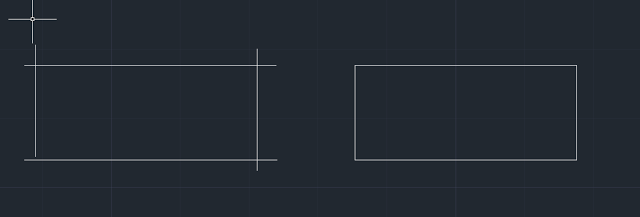
Solution:
You can close the segments into a single closed polyline using the polyline editing command POLEDIT (_PEDIT)... To do this, run the command, select the option Several, indicate the objects that need to be combined into a single contour, confirm that they need to be converted to polylines, select the option Add and enter a tolerance value (the tolerance must be greater than the maximum size of the gap or tail in the path).
To close or trim single pairs of line segments, it is convenient to use the command Pairing (_Fillet)... Run the command, hold down the Shift key and specify two objects - the system will close them. It doesn't matter what value of the fillet radius is set in the command - holding down the Shift key temporarily redefines the radius to zero.
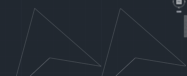
13. Avoid Sharp Corners
Description:
The laser cutting process is determined by three parameters (roughly) - laser power, radiation flux density and cutting speed. During cutting, when there is a sharp change in the path of movement (for example, two sections at an acute angle), the cutting head has to slow down and stop, only then change the path of movement and accelerate again. If at this moment the power and flux density remain unchanged, then the quality of the cut will deteriorate, the material is "burnt out", there are gouges, material melting, etc.
All this applies to machines in which the laser operates in continuous mode... If the machine works with a pulsed cutting mode, then the technologist, when creating a processing strategy, can reduce the laser power in the "problem" areas, in this case it is not necessary to get rid of sharp corners in the cutting path.
Solution:
Sharp corners must be avoided. Round off all sharp corners with an arc of a small radius, in this case, the cutting head of the machine does not have to stop to change the direction of movement, and as a result, you will get the same cut quality throughout the entire path. The radius of the arc should be at least the width of the cut, which for laser cutting machines is 0.2 ... 0.3 mm, but not too large, so as not to violate the functional and geometric characteristics of the part.
14. Avoid too small objects
When developing a part, always take into account the technological requirements and parameters that each machine has. So, for example, if you plan to make engraving, then remember that the minimum size of a text character is 1x1 mm. The thickness of the laser cut is from 0.2 ... 0.3 mm, this must also be taken into account when building sweeps and contours with small elements.15. Export the file to DXF format
To export use the command Save as. When choosing a version DXF format you must be guided by the requirements that the CAM module has - which version it can import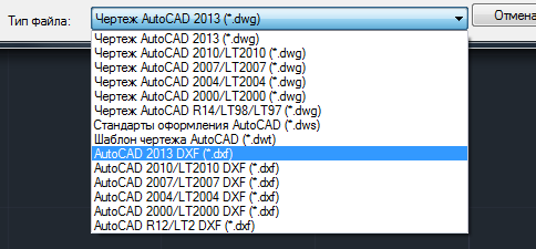
Note that the DXF file can be exported in binary or ASCII format (ASCII is enabled by default). You can switch the format in the window Save options
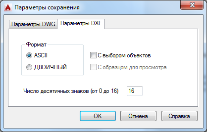
You can also use the command to export EXPORT (_DXFOUT)
Conclusion
I would like to emphasize once again that the implementation of all points is not at all mandatory, in each case you need to be guided by the requirements of the CAM program in which the program will be prepared, the technological capabilities of the machine and its control rack.


 Future marriage of Prince Harry year NTV")


Energy drinks: give vigor, but take away health What will happen if you drink 4 energy drinks
Mustard for weight loss: how to use the seasoning with maximum benefit Is it possible for children to have mustard
The benefits and harms of mustard for the human body Table mustard benefits and harms
How to treat the ear after piercing: types of antiseptics, their composition, rules and features of the treatment of a pierced ear
Sistine Chapel in the Vatican: description, history, architectural features